HOLIDAY DONATION DRIVE - SUPPORT MSW - DO YOUR PART TO KEEP THIS GREAT FORUM GOING! (Only 13 donations so far - C'mon guys!)
×


Piet
-
Posts
3,568 -
Joined
-
Last visited
Content Type
Profiles
Forums
Gallery
Events
Everything posted by Piet
-
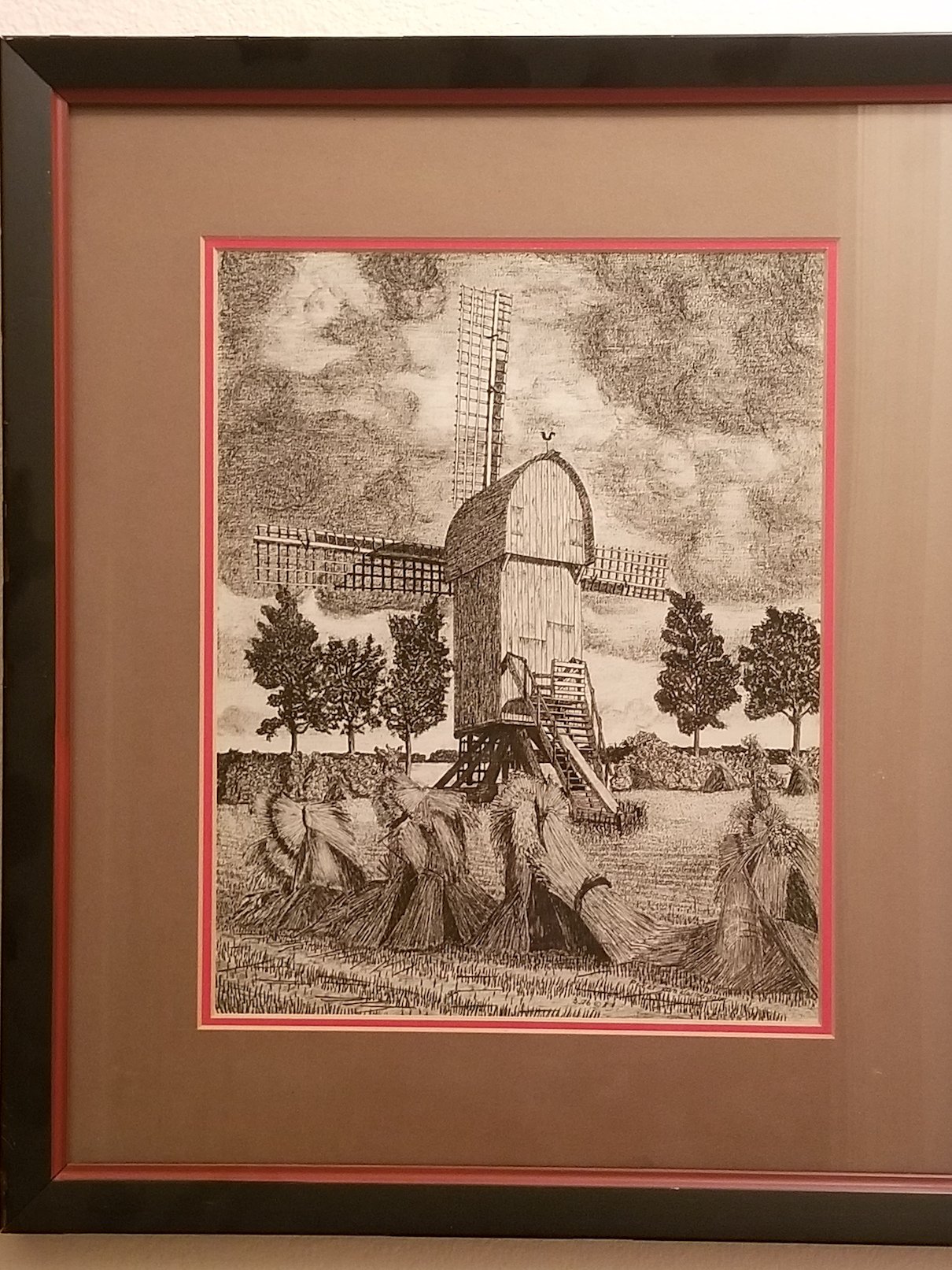
 Yes, that's very nice work Marcus. I believe you have started something with your build. You have generated a lot of interest in these marvelous machines with some good information in the how these things work. Some great links too, which is very much appreciated. It so happens that I have a few drawings on the way from the Netherlands and may just join in building one to sit on my fishpond pump housing. I think a wip watermolen should look real nice there and it'll cover that ugly black lid. Problem is though, that I have to remove it twice a week to clean the skimmer and filter. But that's a small price to pay for having something nice to look at, and typical Dutch. To answer your question Marcus about the lights, no, I have not yet build a mill but a few lights in the VOC ship. My suggestion is to light every floor, assuming the miller lives in the mill. As you know many mills have a separate house next to the mill as their home, not the mill. A solar panel should work nicely. You could also buy a low voltage garden light system, put the cabling in a plastic conduit and bury it. Plug it in with a timer. You do need access to the lamps though because they don't last forever. Just a thought. @ Jan, yes, that's the mill I visited in ter Haar, Drente. We were lucky finding the miller there and had a grand tour of the mill. We even bought a big bag of flour. Here is my pen and ink with ink dry-brush drawing of that very mill. That's the one they transported from the fort in Boertange. That fort now has a replica. the title is: Storm has past. Cheers,
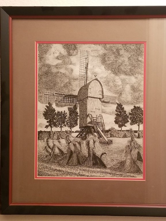
- 268 replies
-
- 10
-

-
Looking forward to your next project Patrick. Radical is an understatement I think. It would be helpful getting a few pics of the interior and furnishing. Just a word by word description of how the decks were laid out. A general verbal description of the hull perhaps? Cheers,
-
Very nice work Nils. I marvel at the ingenious way rigging the shrouds. Cheers,
- 692 replies
-
- 3
-
-
- eagle of algier
- chebec
- (and 2 more)
-
Carl is right, and with your comment it's just a simple job by starting from the bottom up. Your jewelry making skills show with how neat and precise everything is. These closeups can't hide much, very nice work JesseLee. Cheers,
- 1,306 replies
-
- 10
-
-
- syren
- model shipways
- (and 1 more)
-
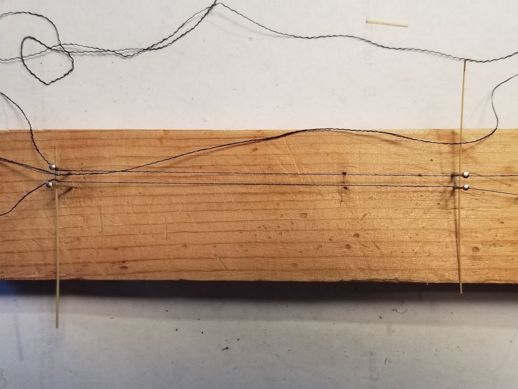
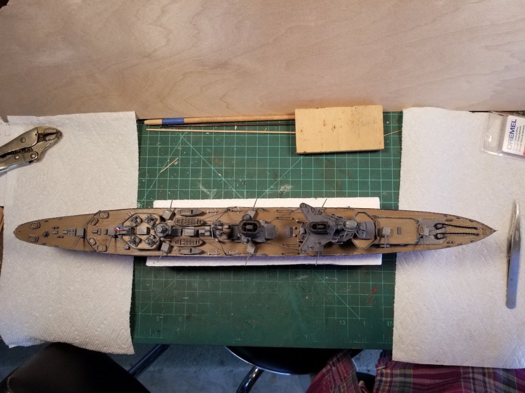
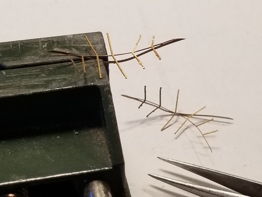
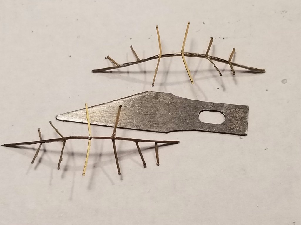
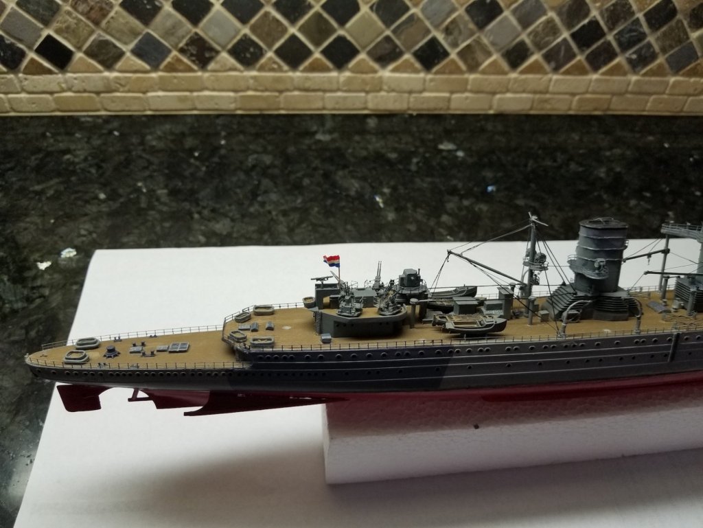
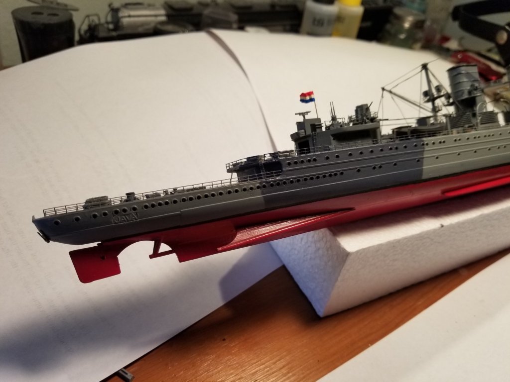
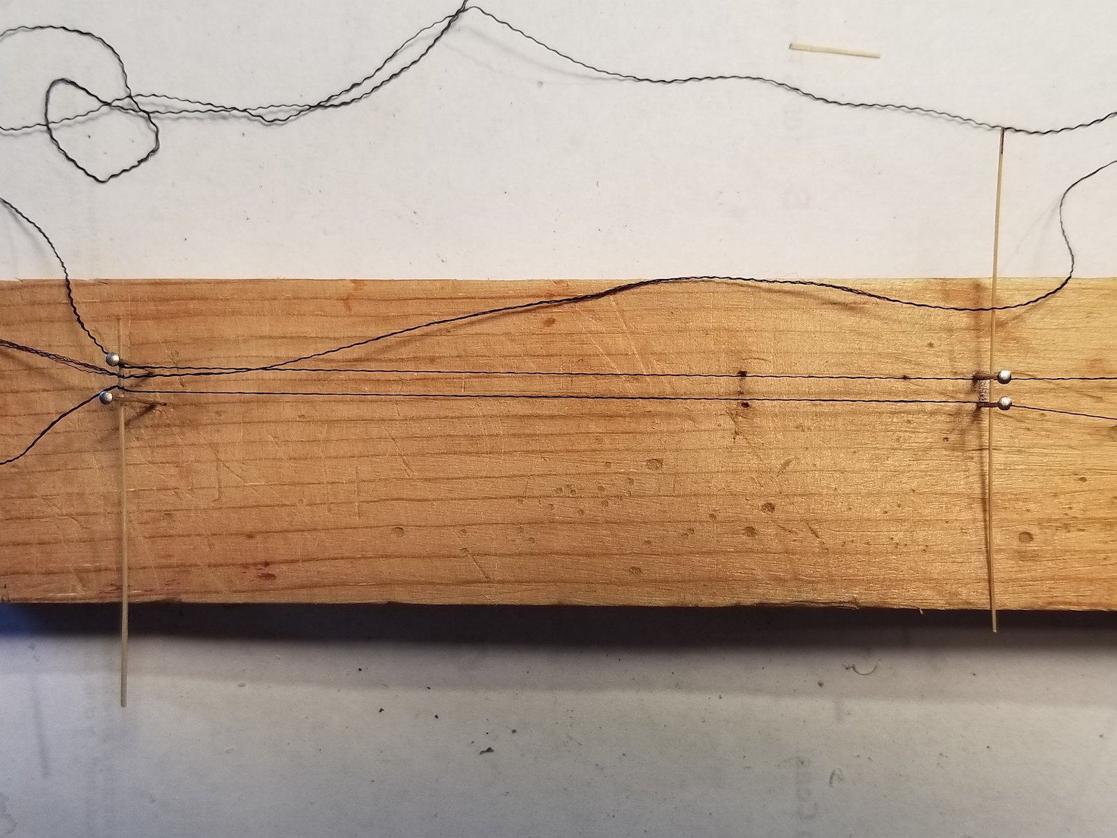
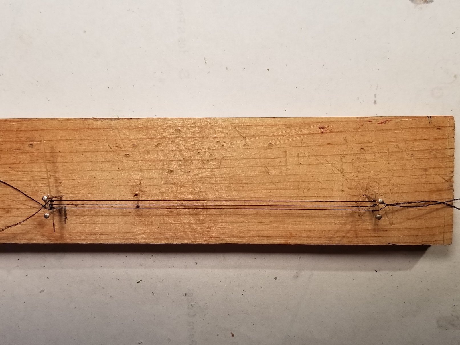
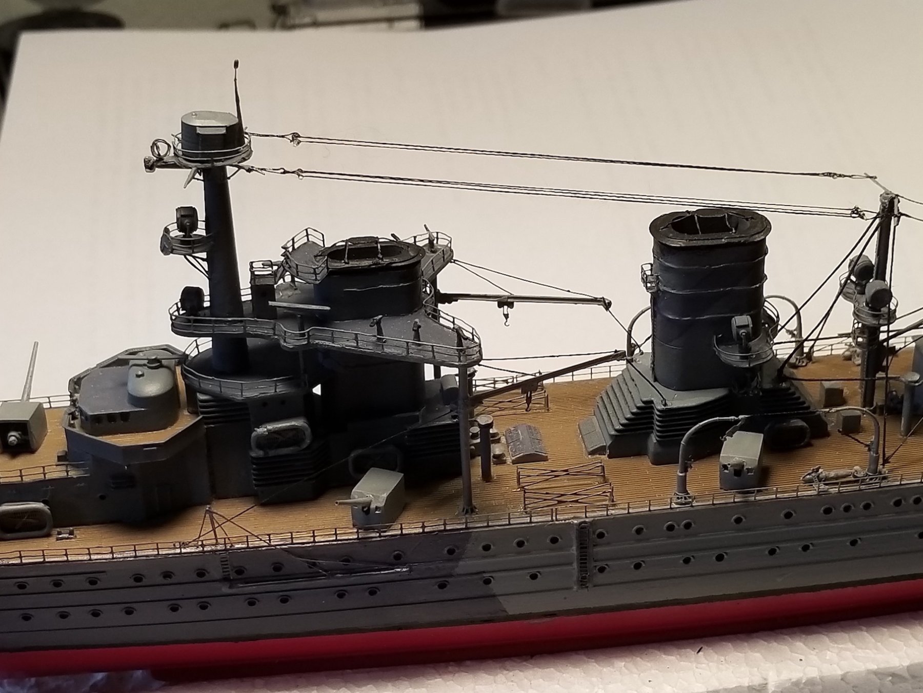
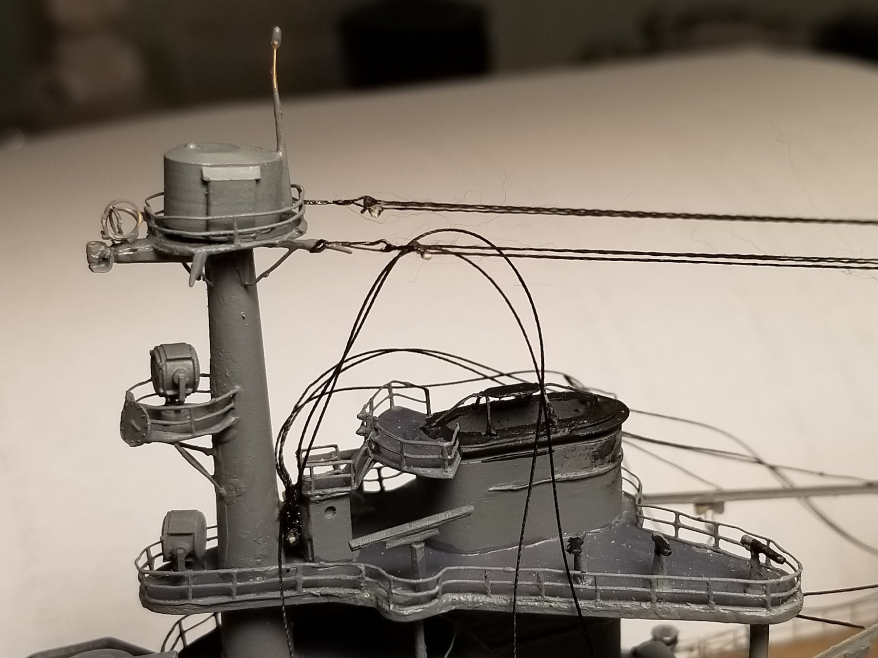
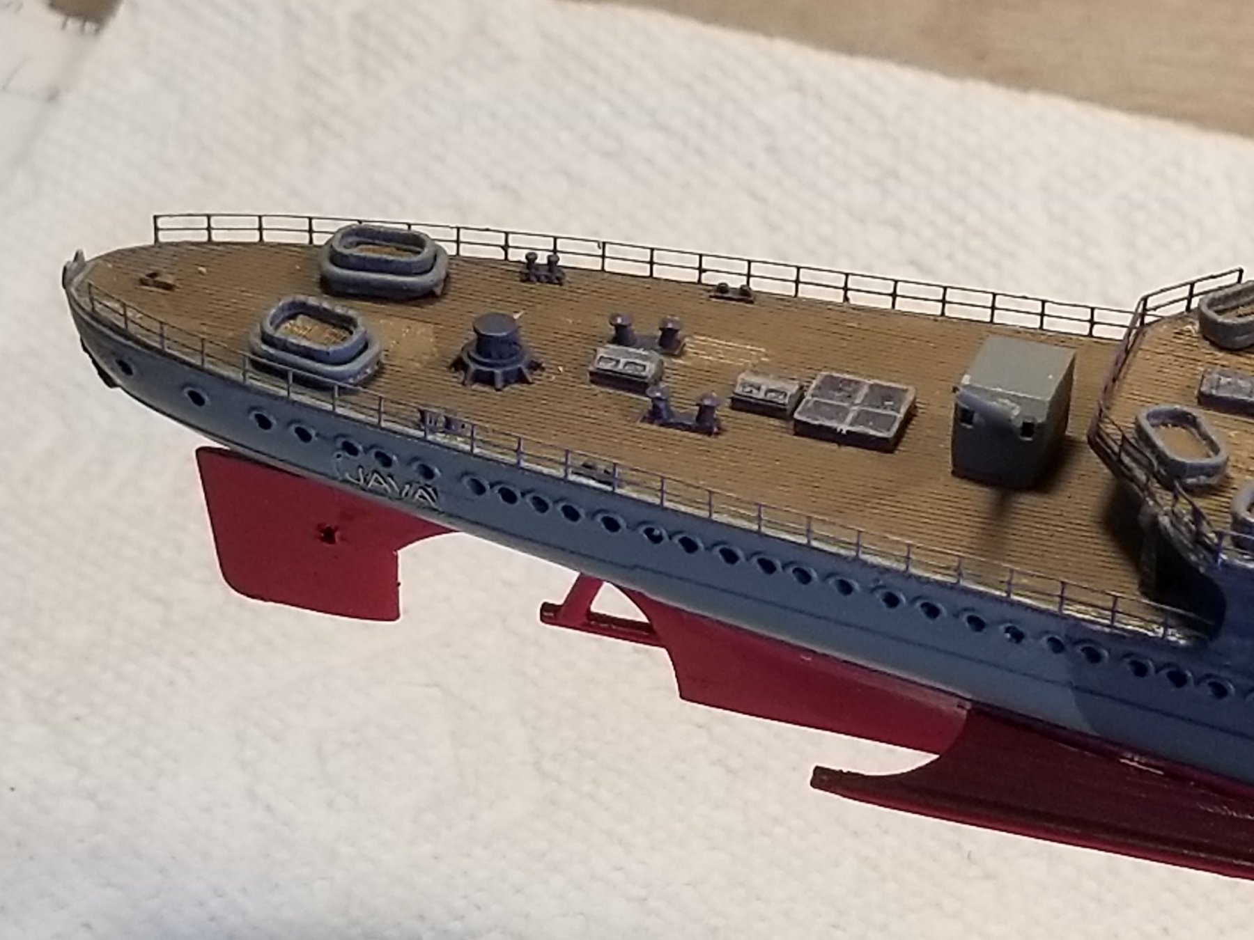
Hello everyone and thanks to all who clicked the like button. I had a busy morning, trimming two hedges and a bunch of azaleas in the back yard. Then lunch and read my e-mail. Finally I managed to do something on the "Java" model. Well, I finally caught up with the backlog and we are current - hurray for that. The last two days I worked on the antennas. Rather then trying to make four round thingies to fasten the six wires to, as the instructions show,, I used slivers of bamboo. Next came the wires. Any thread I have is much to thick, including very thin silk. I split 6 pieces into three strands but the problem with this is that it maintains the twist, no matter what I tried. Well, not everything, I should have used Gwen's iron to heat it up a little. However, with a slight pull it disappears. So, I made a jig and tapped two pairs of sewing pins into the wood, spaced so it gives me the right distance between the attaching points. Added the bridals and attaching cable. Looked good in the jig. Now came attaching it to the PE beams, one on top of the rear mast and the other on top of the main mast. I actually needed three hands but somehow I managed to wrestle these flimsy assemblies to the beams. I tine spot of CA, holding the antenna between two hands and gently holding the attaching cable to the beam, at the right spot. Couldn't breath while holding it so as not to let it slip from the dedicated spot. An old mark's man trick. This afternoon I started on adding the wires going down to that little house in front of the forward funnel. I have no idea where they are supposed to enter this little house but I used the bamboo sliver trick again. First I tied all six pieces of thread to it with a simple overhand knot, a dab of CA, let it cure and then cementing it to the forward side of that little house. That's about all I could to for this day. Hopefully tomorrow, after I finish trimming the two hedges, I can cement the wires to the bridals. Another tedious job. With all the handling I accidentally brushed against the little flagpole with the decal flag and it popped off with the flag in two pieces. Now I have to make another flag for the "Java." I think of getting some cigarette paper and either paint a flag or try my last decal on the paper, which could be tricky. In hind site I should have waited with cementing the flagpole with flag to the ship after it was in the diorama. Oh well, no one is perfect. Part of the installation instructions. The first antenna assembly in the jig being worked on. Here you can see what mentioned about the twist in the thread. The last one completed. Here we see both antenna assemblies cemented to their attaching beams. Six wires are now attached to the little house. They'll be cemented to the same beam as the assemblies. Right now they are just draped for the picture taking. I did not separate the thread for this because I cannot put any tension on them And yes, the flagpole will be straightened and the ship will be checked for any other damage and paint touch-up, including a new flag for the aft flagpole. Cheers,
.thumb.jpg.b8f81b87977f639e37dbfb7a1b7abceb.jpg)


- 378 replies
-
- 12
-
-
- java
- pacific crossroads
- (and 2 more)
-
I'm in Marcus, a little late and I hope there is a seat available. Great start and a very nice ship tp model. I have the drawing set too, so many to choose from and so little time to do them all. Cheers,
-
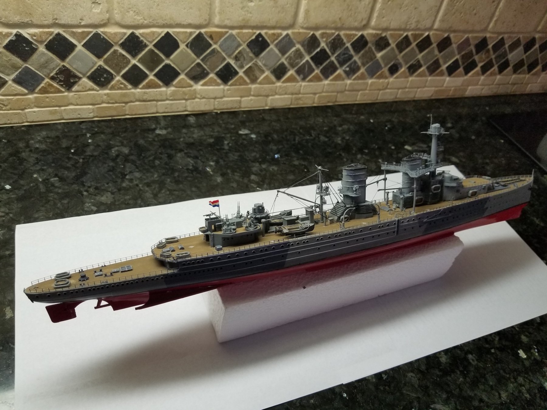
Thank you Mark, Jan, Ken and Denis for your kind comments. Oh I understand that the like response does not mean you liked what happened but just to indicate that you read with understanding. I really appreciate your likes. Actually what is bothering me emotionally much more is the time I was in Japanese concentration camps and then the Indonesian war for Independence after the war was with Japan was over. That is still very difficult talking about without choking up. I am touched by your supportive reaction, that means a lot to me. Okay, time to start putting the last few parts on the ship, checking for touch-ups and start with the diorama. See all of you on the next post. Cheers,
- 378 replies
-
- 9
-
-
- java
- pacific crossroads
- (and 2 more)
-
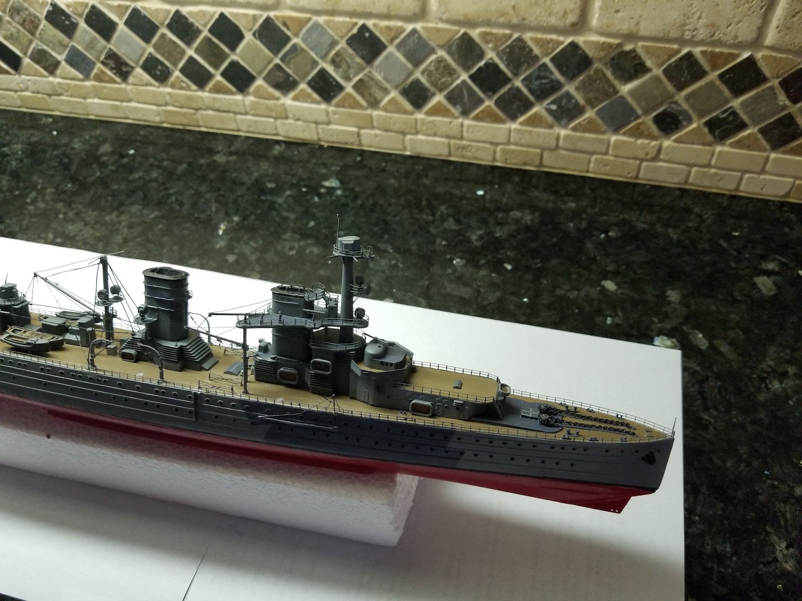
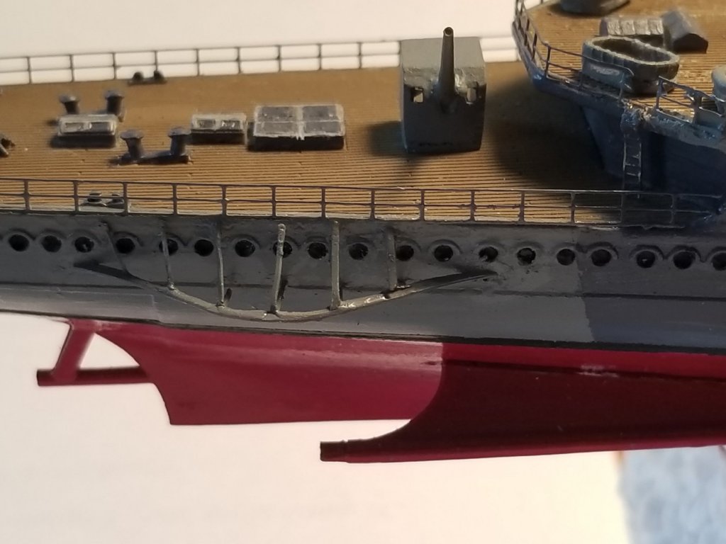
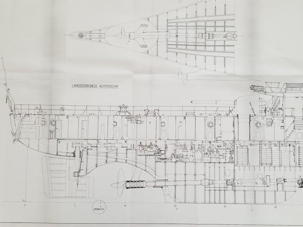
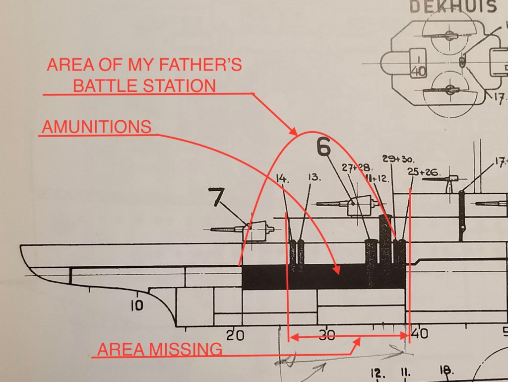
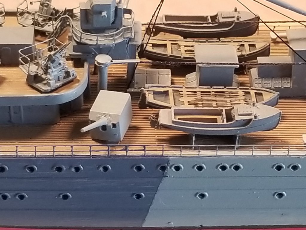
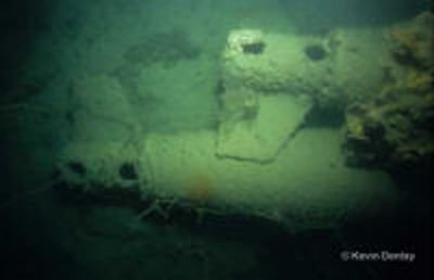
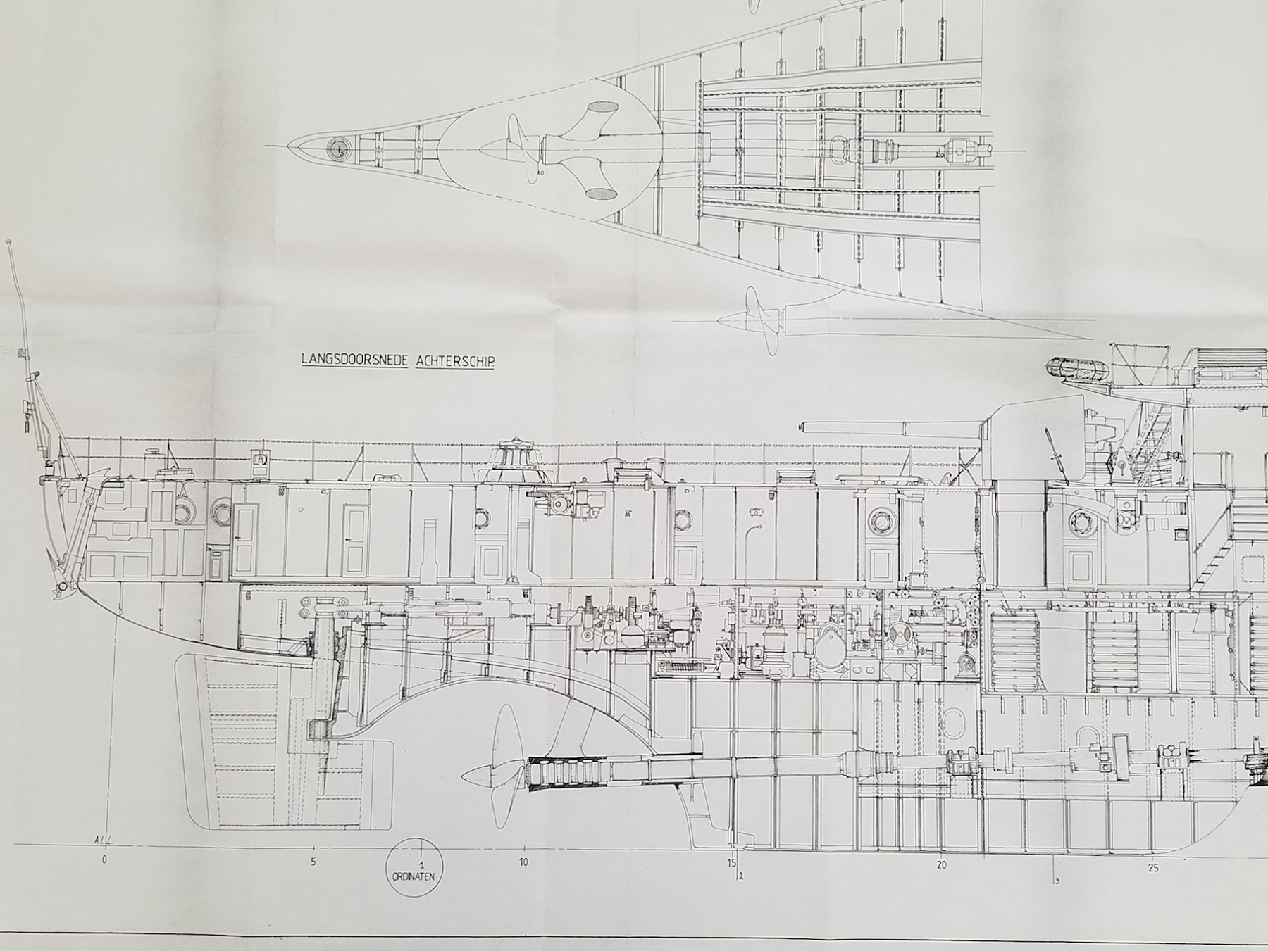
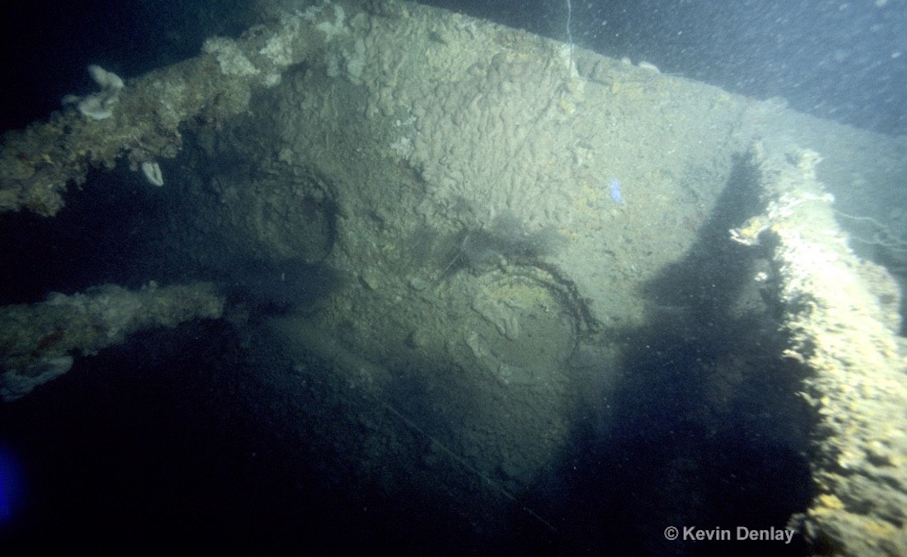
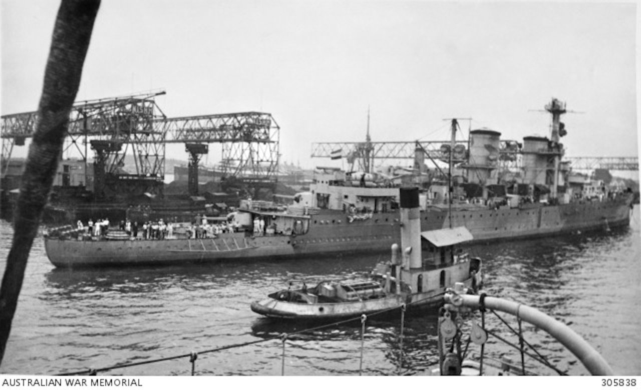
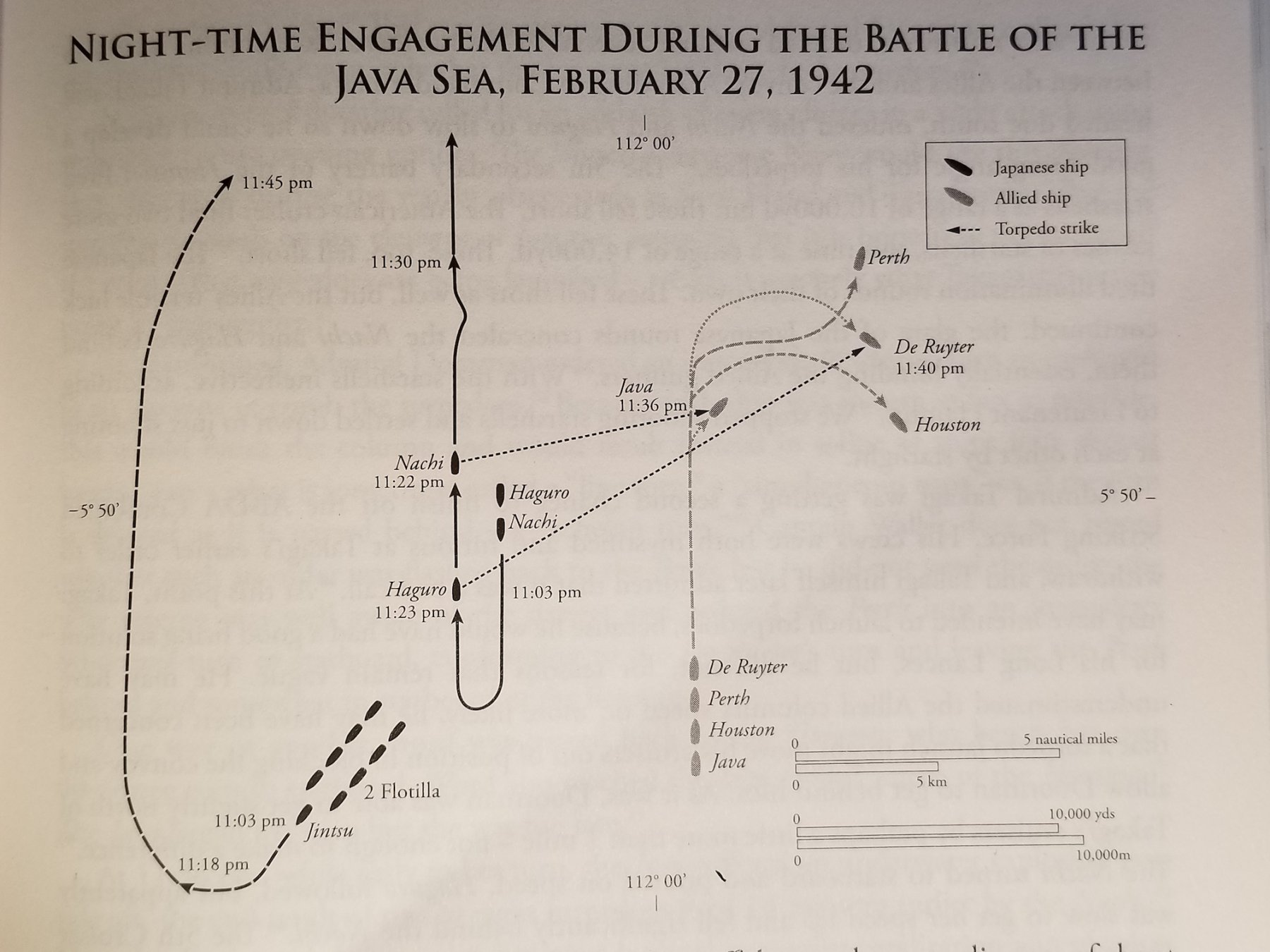
Hello everyone and thanks to those who came visiting and clicked the like button, it's much appreciated. This is my second attempt placing a post. Last evening, in the middle of pounding away at the keyboard it just disappeared into cyberspace. No idea what and why. This post is for days 59 and 60, which brings us to march 19. On day 59 I cemented the previously assembled propeller guards to the aft hull. I then cleaned the hull area from some excess cement and painted the propguards and the aft hull section. That was all I could do. I changed my mind on the depth charge launching ramps so on day 60 I cemented them to the fantail. I omitted the guide railings the kit provided because i did not see them on several photos or on the drawings. However, I made two posts to cement next to the anchor cable guide and cemented a piece of PE wire to the posts and the end of the railing as shown on the drawings. I think that this arrangement works for me. With your indulgence I would like to add the missing details of "Java's" sinking and the death of my father with the crew he served with. As I have mentioned before the aft section of the ship has special meaning to me because that's where my father's battle station was. For a long time I did not know this and how he may have died. All this came to light for me in stages, separated by many years in between bits of information. I have attached a few pictures to help you in following me. The first bit of information I received was at a lecture by a surviving naval officer fron "Java." That was sometime in 1954 when I served in the Royal Air Force when based at the airbase in Deelen, near Arnhem, Netherlands. This officer talked about the Battle in the Java Sea and the sinking of "Java" and Admiral Doorman's flagship "de Ruyrter." After his talk was done he opened it for questions. Obviously my hand went up too and when it was my turn I introduced myself by rank and name. He instantly became quite excited and asked me if I was related to Adjudant van Warmerdam. I responded in the affirmative and told him the I am his son. He immediately adjourned the meeting and told me to come see him. He invited me to the Officer's mess at the base and we had a long chat. The main point in our conversation was how my father was killed. He informed me that the aft gun fall on him due to the explosion. and that part of the ship almost immediately broke off and sank. Now at last I had confirmation of his death and no longer had to worry about the possibility of him having been a POW of the Japanese and died in a POW camp. The next bit of information came to me from Kevin Denlay, an Australian diver who was part of the crew of the research vessel looking for the wrecks of the ships sunk in the battles against the Japanese Imperial Navy. I stumbled on his writings and posted photos doing some research on my computer. I contacted him and in the conversations we had via e-mail I learned that the stern section lays about 100 yards behind the main body of the wreck. The most aft 15 cm gun was at the edge of the forward section, laying askew and half way below deck level. After I told him what the surviving officer mentioned to me back in 1954 he had to agree that this gun, the #10 most aft gun, did indeed appear to have fallen down. The support pillar had collapsed down taking the gun with it due to the hull's structural failure caused by the explosion. These two bits of information confirms it for me with Kevin's agreement, that this was indeed my father's battle station and must have died instantly. Kevin also told me that the stern section deck was missing as if peeled off like the lid of a sardine can. He also told me that a part of the hull between the aft side of the AA gun deck and the forward end of the stern section seem to be missing. This too corroborates what the Dutch Naval officer told me and the eye witnesses of the US cruiser Houston. They heard two explosions, the second following the first by several seconds. Both these witnesses saw parts of the hull and bodies fly over 100 feet into the air. Kevin never found the #9 gun on subsequent dives. Now that the wreck has been lifted from the sea floor I think that Kevin would not hesitate allowing me to show the photo of the #10 gun. I think it is too important a piece of evidence to miss. As a trained accident investigator for the Federal Aviation Administration I had no problem piecing these things together to form a clear picture of the events. This information is not known to anyone, beside my immediate family, till now. The Japanese long lance torpedo struck "Java" on the port side aft of the armor belt. This is the weakest area of the ship and the power of the explosion exceeded the structural integrity many fold over. It was also where the aft ammunition area is. It was stocked with depth charges, 15 cm shells, cordite packs and the 40 mm ammo for the Bofors guns. It does not take a genius to figure out what devastating results an exploding torpedo has in that confined area. To be sure - I am at piece with this - knowing that my father and the crew of "Java" died an honorable death and should be remembered for their heroism in fighting a non winnable battle. When my father came home the day before this battle he and I had a man to man talk where he told me that he would most likely not come back. He also gave me certain orders that I had to affirm with a handshake. I am happy to say that I have been able to achieve all I promised him, in spite of many roadblocks thrown in my way. I am sure that he would be very pleased with my accomplishments in life. Okay, here are a pictures with further explanations Propeller guards and depth charge ramps installed. Closeup of propeller guard with the #10 gun. Compare this with Kevin Denlay's photo a few pics below. Stern section A low res picture of "Java" being resupplied and fueled in Tantjong Priok, Batavia (now Jakarta). My father was on her when this photo was taken. Part of the propeller guard. As can be seen that the deck is missing. A graphic illustration of my explanation. A copy of my 1:50 scale drawings. The #10 gun support gave way due to the collapse of the support structure below it, caused by the explosion. The area below the stern deck holds the officer's quarters. This is Kevin Denlay's photo of the #10 gun. This now is my father's grave marker, even though it is no longer on the sea floor. This is a copy from Jeffrey Cox's book "Rising Sun, Fallen Skies." Perth had make an immediate turn port to avoid De Ruyter. Houston witnessed both sinkings. Cheers,


- 378 replies
-
- 6
-
-
- java
- pacific crossroads
- (and 2 more)
-
Hey Marcus, I'm in as well. A polder mill is also on my bucket list! Oh - - already since the year needle naadle noo. Not knowing there are plans available I was planning to draw my own plans but buying a set is easier. So, someday I'll spring for a set of plans. I have visited a working grain mill in Groningen and the one in ter Borg, Drente, which is one of the oldest post mills in the Netherlands. That one stood on the defensive wall of the fort Boertange and is owned and operated by the city of Groningen. Then of course a few in Koog aan de Zaan. We were also fortunate being invited by the miller in the one he lived in near Alblasserdam. Just like the Dutch ships these wind mills have something special about them. Yea, call me sentimental but they are beautiful. Quite a nice project Marcus and how are you planning to simulate the thatch siding? Will you also make it working? Cheers,
-
Very nice progress Denis. Cheers,
-
Wow, impressive work kevin. Cheers,
-
Hey Greg, good seeing you here. I was not aware that Face Book shows dioramas. I don't do FB though, long story about that. Has to do with my work for the US Federal Government I was part of. Need to keep a low profile, even on this forum I have to be careful with what words I use. Some trigger a "blip" on "their" screen However, I have found and saved quite a few dioramas from YouTube, all very interesting with good info in the how to's. @ Carl: My proposed diorama size is 24 X 8 inches. Display space poses a minor problem but I'll figure something out. True about your comment on my 1:2000 scale diorama of a New England shipyard with two topsail schooners in the stocks - inside a 60 watt light bulb. I don't know if that is hot-linked in my signature. I needed a seeing-eye dog to help me with it Am currently working on a 1:3000 scale diorama of Young America or some sort of a clipper ship. I set it aside for the time being to work on the "Java" but will continue after it is done and simultaneous work on the VOC ship again. Good to see you here again John Allen, thanks for your kind comment. Yep, that's why I have my trusty seeing-eye dog at my side. No, just kidding - I use 3X reading glasses that gives me ample magnification. A 1:350 scale is not all that bad, just the delicate PE has posed a few problems, mainly that I am not familiar with it. In retrospect, I will do certain things different in the future - if I do another kit with PE - to prevent these thin wires to misbehave. I started my next post on "Java" yesterday evening and half way through it just magically disappeared. Now I have to start all over again, bummer. Especially in that it will be very personal to me. So stay tuned. Cheers,
- 378 replies
-
- 8
-
-
- java
- pacific crossroads
- (and 2 more)
-
Thanks Carl for your faith inn my "prowess." Actually due to the added lower half of the hull will make this a little more - - ummm, challenging. Normally the sea part is about 1/4 or so inch thick but in my case it's a half inch from the keel to the waterline. My plan is to use a smidg'n over 1/4 inch of white caulking compound first, then lay the ship in it and let it cure. Then follow up with an epoxy fake water with a blue dye mixed in it to form the sea. It is supposed to allow time for some modeling but needs to be followed with another two part epoxy to model the waves. In any case it'll be an experience and keep my fingers crossed. Boris has send me a bunch of pics and URL's of dioramas. All look very good. There are plenty on the internet too. Yeah, I read that article in the NRG. That would not work for me because I need an opaque sea due to the lower hull. Cheers,.
- 378 replies
-
- 7
-
-
- java
- pacific crossroads
- (and 2 more)
-
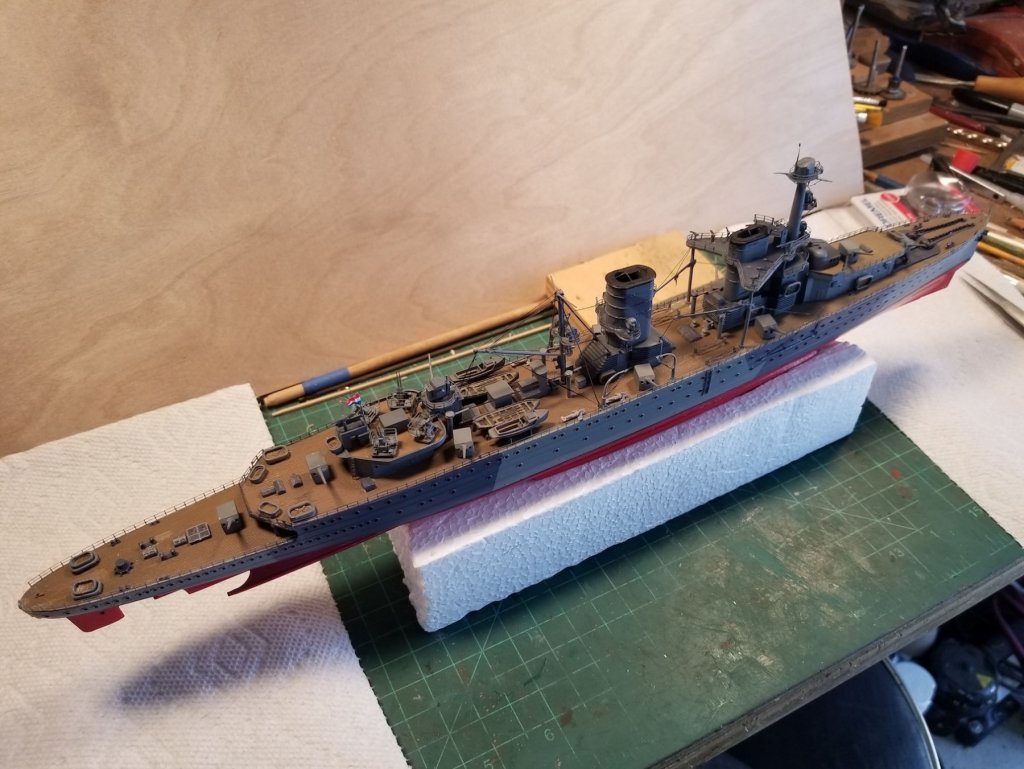
Thanks Denis and Carl for dropping in and your kind words. Not quite close for her maiden voyage Carl. I think that the biggest challenge is still ahead of me, the diorama frame and sea. I bought a piece of molding today for the base sides and to retain the sea material. I have a 1/2 inch thick panel from an old cabinet that'll serve as the base. I think I'll make it 24 X 8 inches, that'll give the ship ample room. I plan to place her in a somewhat diagonal position allowing me to add two missed shell bursts in the areas of more sea space. Wish me luck with it. Cheers,
- 378 replies
-
- 5
-
-
- java
- pacific crossroads
- (and 2 more)
-
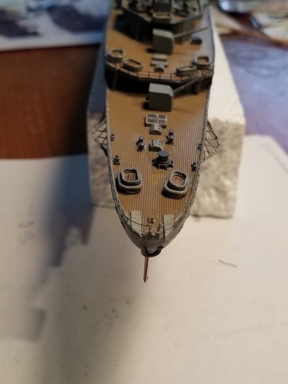
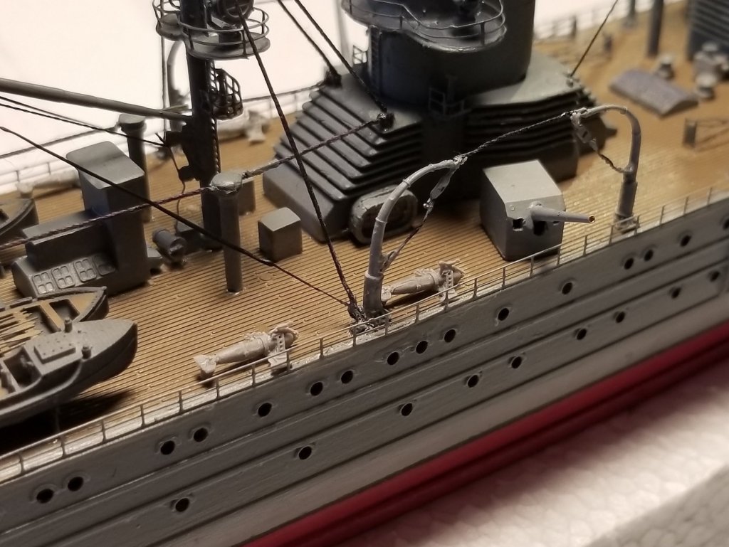
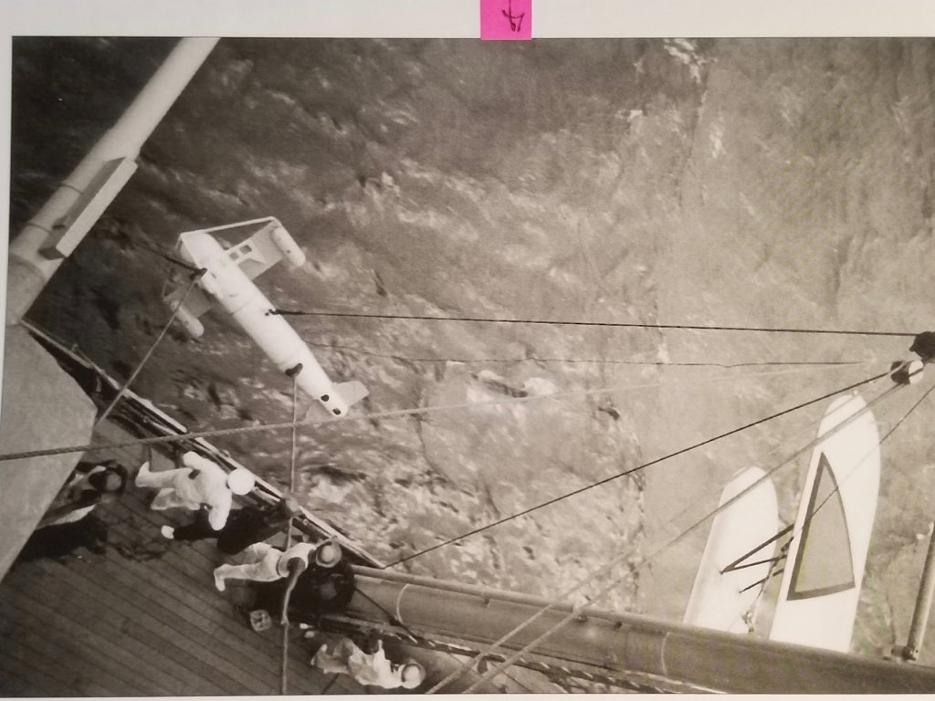
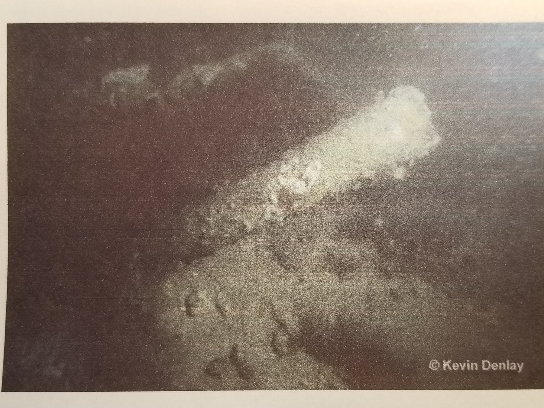
Hello all and thanks to those who visited and clicked the like button. This post is for Day 58, which brings us to March 16, 2018. This day I cemented all ten 15 cm guns to the model as I perceived them to be positioned. I also cemented the 4 paravanes to the locations as shown on several photos. Today's work didn't take much time so I also started to assemble the two propeller guards. I have attached a bunch of pictures of this day's progress. The number 10 gun that holds special interest to me. More about that in a future post. Yep, also some paint tough-ups. A close-up of the number 10 gun. The light overhead puts a lot of shimmering on the uneven glue spots. The Dutch National flag made from a decal. I may remake it from thin paper. The Bofors gun in the left back will be repaired. Accidentally hit it when handling the model. All four paravanes cemented to the deck. An actual photograph of a paravane. I painted mine in light grey. Another actual photograph of the crew handling a paravane. This is a photo Kevin Denlay took, showing the tail fins of a paravane, on one of his dives on the wreck. He stated that tihs one was on the sea floor amidships. Overhead shot of the model howing all 10 guns cemented to "Java." Another overhead shot. The two parts for the propeller guards being cemented together. The completed propeller guards ready for dressing. This job was like shoving two wet noodles together. Cheers,

.thumb.jpg.f33b230576301150be5b4231f855f03c.jpg)
copy.thumb.jpg.3560762c2d4082b17828c3cc00de38a1.jpg)

- 378 replies
-
- 9
-
-
- java
- pacific crossroads
- (and 2 more)
-
Nicely done Kevin. I would think that nonskid is applied in areas of most expected traffic, so it looks like you may have nailed it. The only nonskid I ever painted was on aircraft wings Hhhmmmmm, snow eh, that's a dirty 4 letter word here in Florida, today was only 82 F or 28 C. This meant yard work for Pieter. Cheers,
-
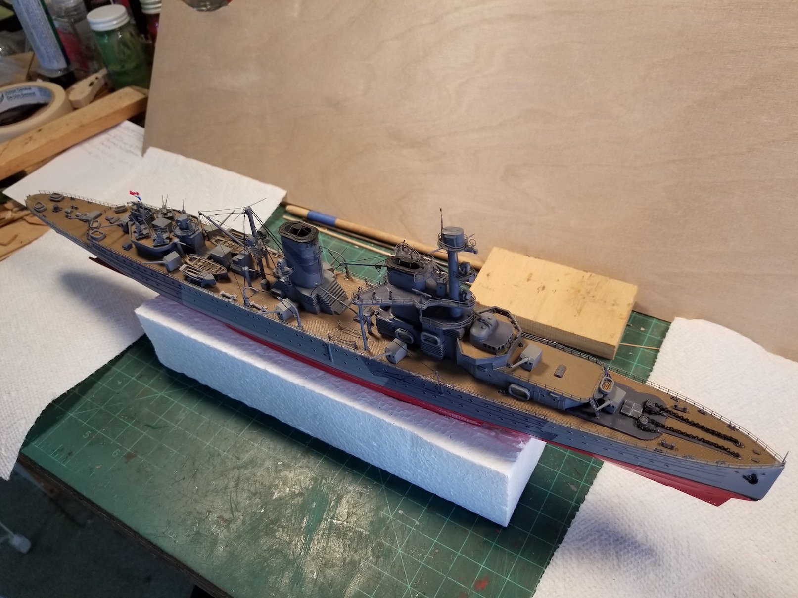
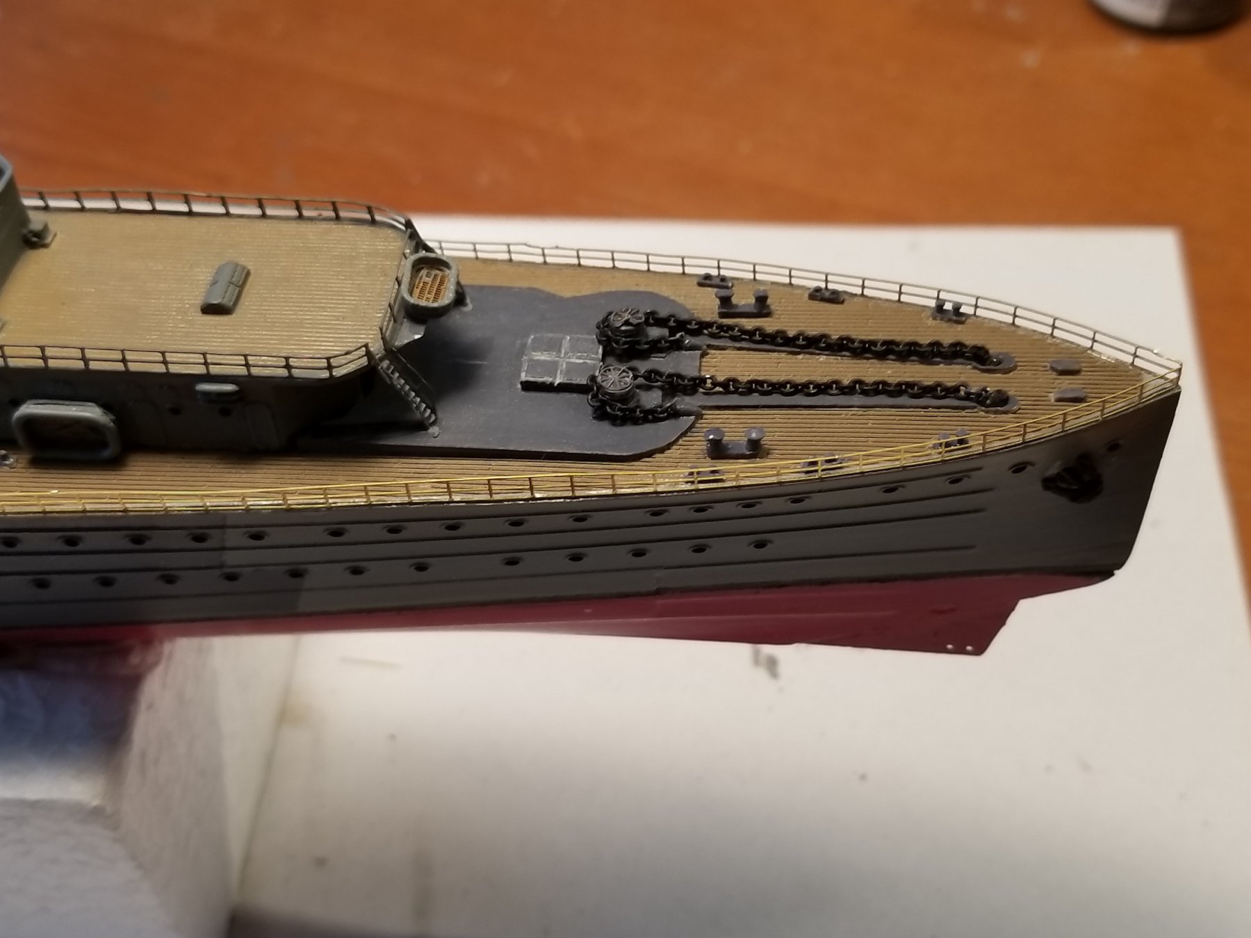
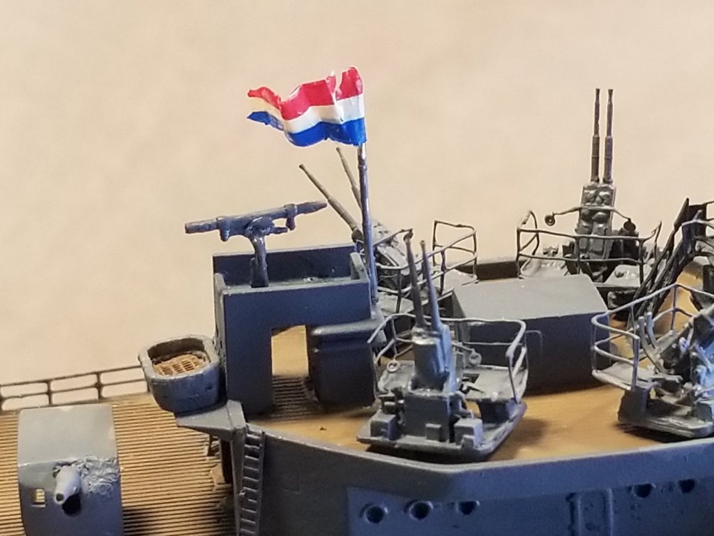
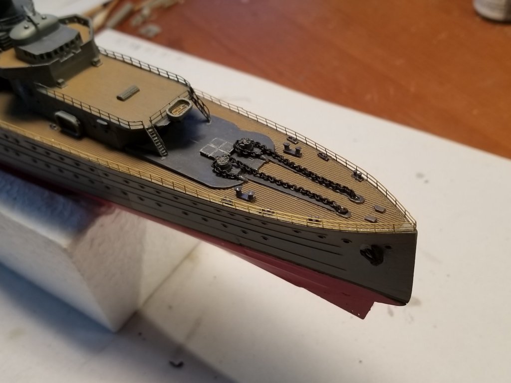
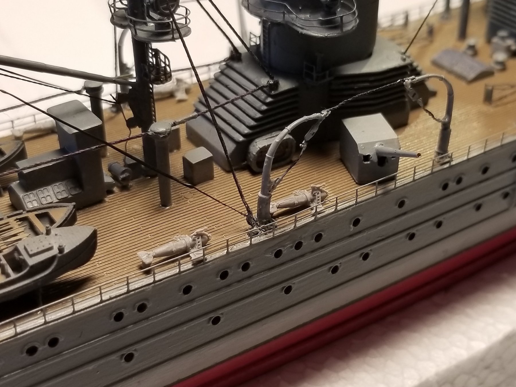
Thank you Lawrence for visiting and your kind words. Also my thanks to all who clicked the like button, This post is for days 54, 55 56 and 57, which brings us to March 12. All these days involve mainly the installation of all the deck railings with some associated items. Day 54 on March 6 I planned on cementing the stern deck railing but needed to think about it a little first. You see, the PE parts are made to fit between the aft main deck gun platform and the depth charge launching ramps at the fantail. Here then is my dilemma, None of my photos of "Java" show these ramps, nor the flagpole at the fantail. I already looked for a longer PE railing I can use to close the fantail. But then I thought, why not cement the railing meant for it and add a simulated cable type addition as I have seen on a few photos. These railings are foldable anyway so my thinking makes sense. I need to do some more thinking on it. That brought my attention to the bow railing but before I can install any railing i needed to install the refueling rig on the main deck. It would otherwise make it too difficult to do. I needed to drill a small hole in the deck for the supplied brass rod where the PY support rigging is to be attached to. In reality this is quite a complicated rig but at this scale Boris did a real nice job simulating it. A shame that it kinda gets lost due it's small size. Day 55 on March 9, I started to cement the forward railing. I started at the bow first with a small dab of cement and let it harden, then slowly bending the railing following the curve of the bow and tack cemented it as I went along to the end of that railing. Next I followed through with the thin CA along the bottom of the railing. I used the same method for all the railings, which proved to be working real fine for me. At least I had no damage to the railing. I also cemented the small flagpole against the forward side of the AA gun deck rangefinder house. Now the flag. Boris supplied two small decals with the kit but can't use them as a flag - - - or can I? So okay I tried and soaked the decal in some water and slid it off the paper, folded it around the flagpole and bingo I had the flag. Problem is that it's just too delicate and I can't make the flag wave in the breeze. So I gently brushed some thin CA on it, let it harden a little and then made a few folds in it. As long as nobody touches it it'll be fine. Days 56 and 57 were occupied with cemented the rest of the railings to the ship. The # 9 gun deck was a little difficult due to the ladders going up. I had to improvise with some spare longer pieces because of the gaps for the ladders but in the end it worked out just fine. Next was painting them following the camouflage scheme on the hull. I'm rather pleased with the railings. Below are a few pics of the railing project. The next installment will show more on how they look. Cheers,


- 378 replies
-
- 10
-
-
- java
- pacific crossroads
- (and 2 more)
.jpg.c83420db467e5cfed372648102432b6b.jpg)


.jpg.30f9943d292a2a2b25ba9351848c1732.jpg)


copy.jpg.2149d6c4d2a9e7b518f01cfc7691a09f.jpg)