HOLIDAY DONATION DRIVE - SUPPORT MSW - DO YOUR PART TO KEEP THIS GREAT FORUM GOING! (Only 13 donations so far - C'mon guys!)
×


Piet
-
Posts
3,568 -
Joined
-
Last visited
Content Type
Profiles
Forums
Gallery
Events
Everything posted by Piet
-
 Wow, impressive work Kevin. Cheers,
 -
A lot of progress Denis. The smaller beads look much better for the doorknobs. Cheers,
-
Exceptional nice work Denis, with all the detail on that little boat. Cheers,
- 378 replies
-
- 3
-

-
- t78 norden
- billing boats
- (and 1 more)
-
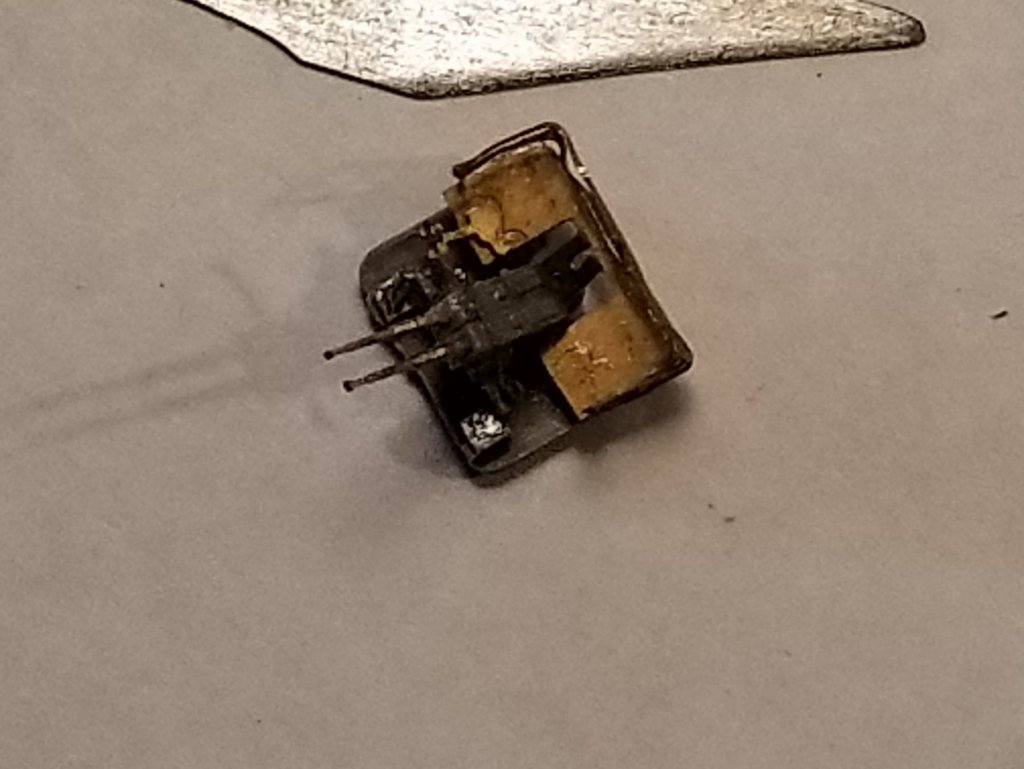
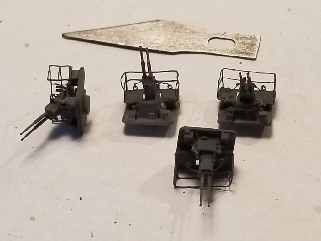
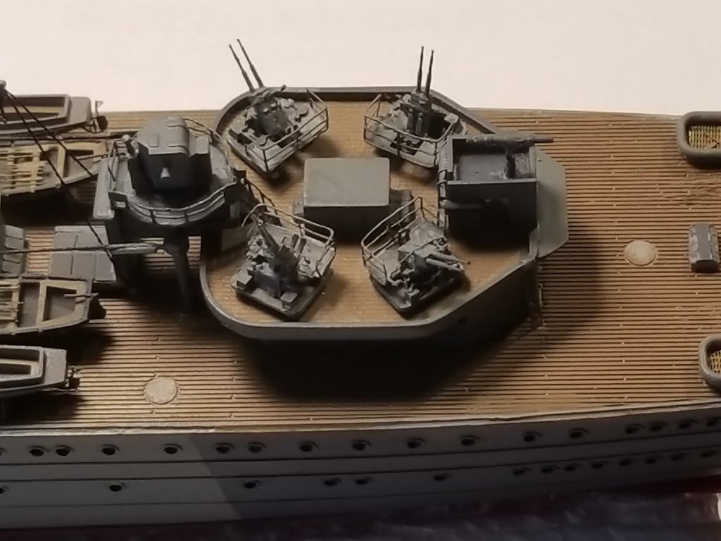
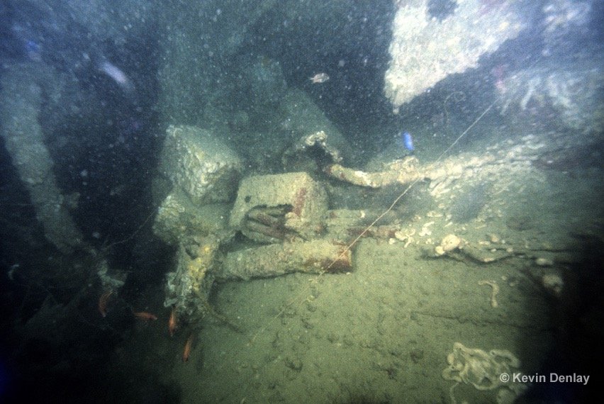
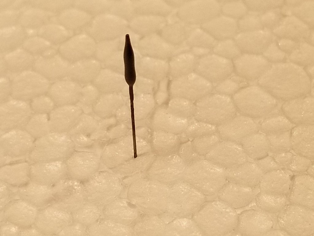
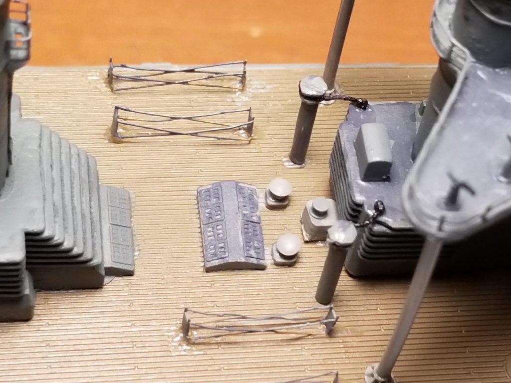
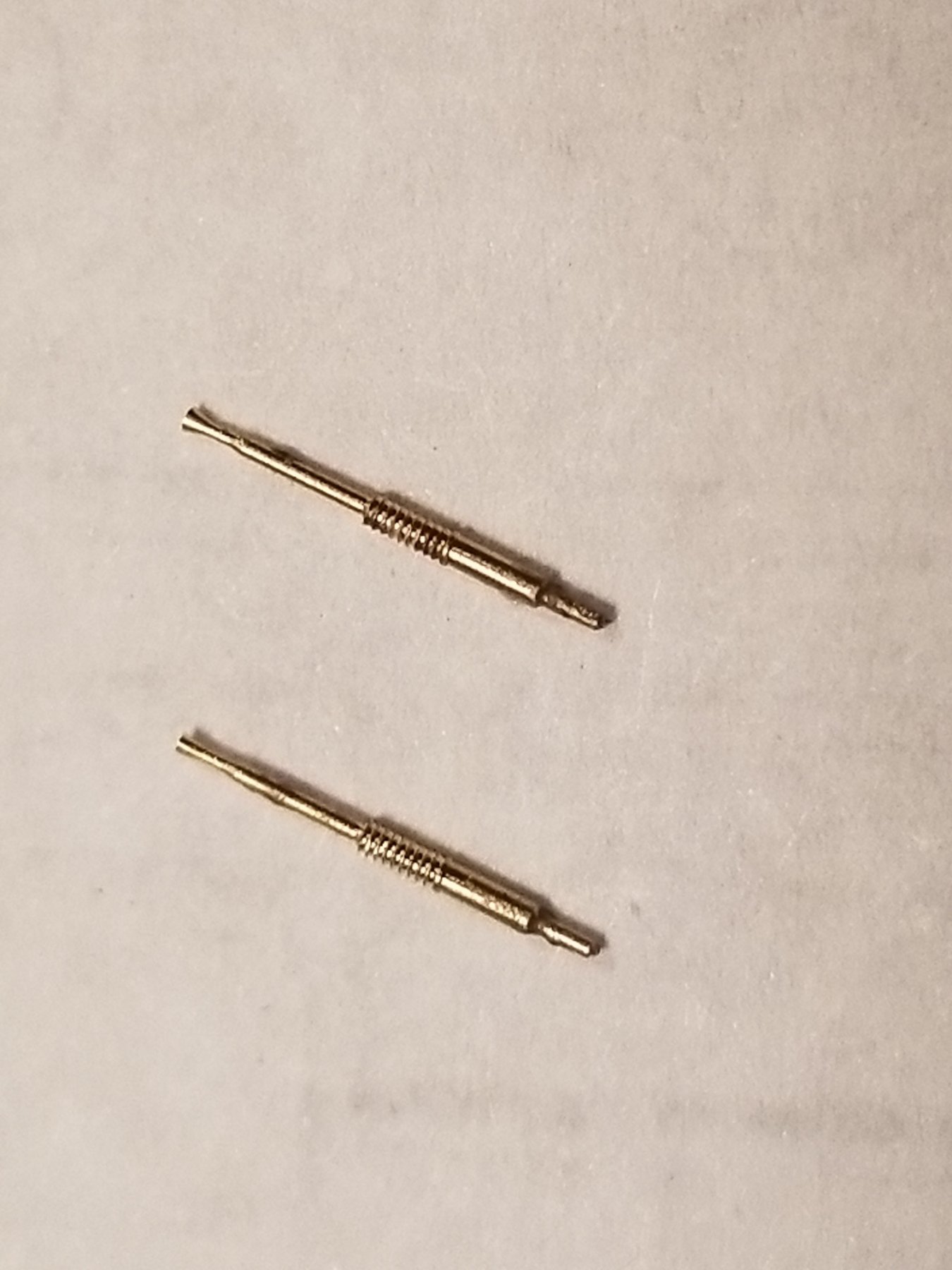
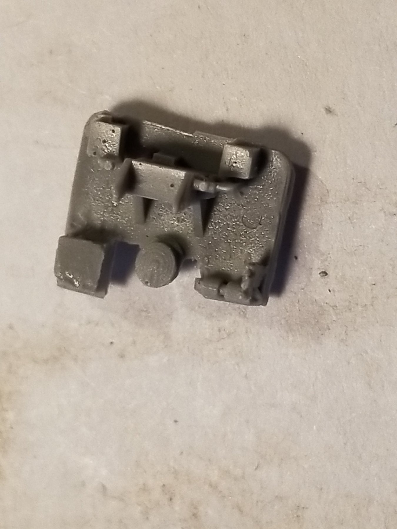
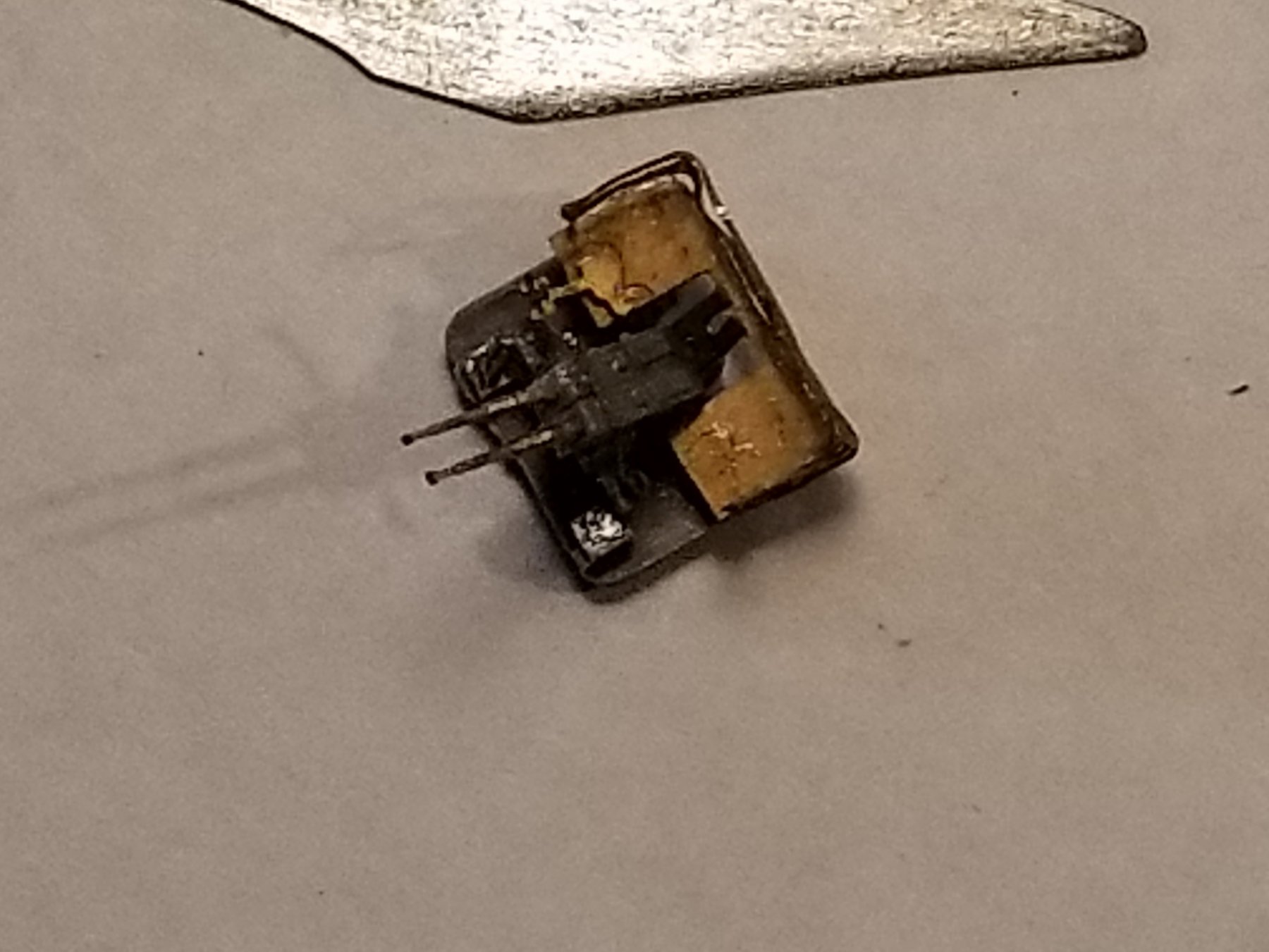
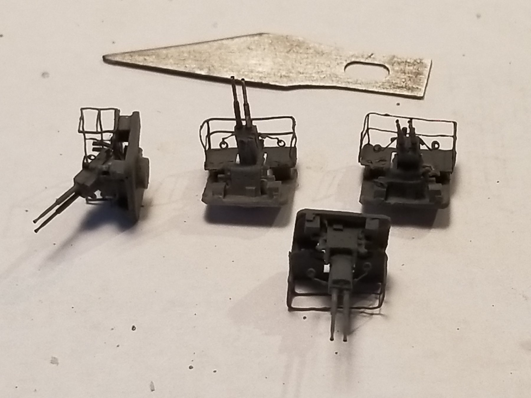
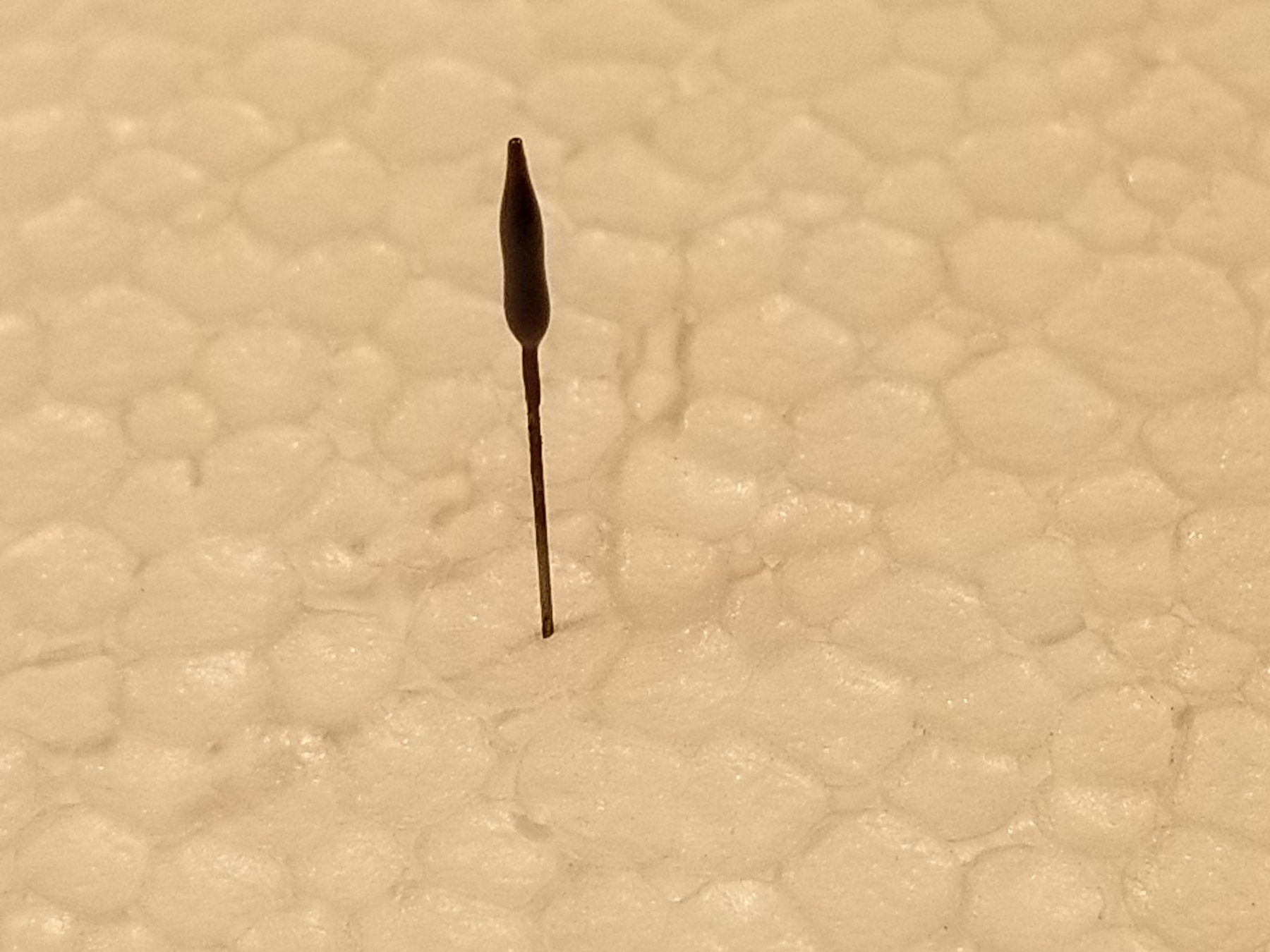
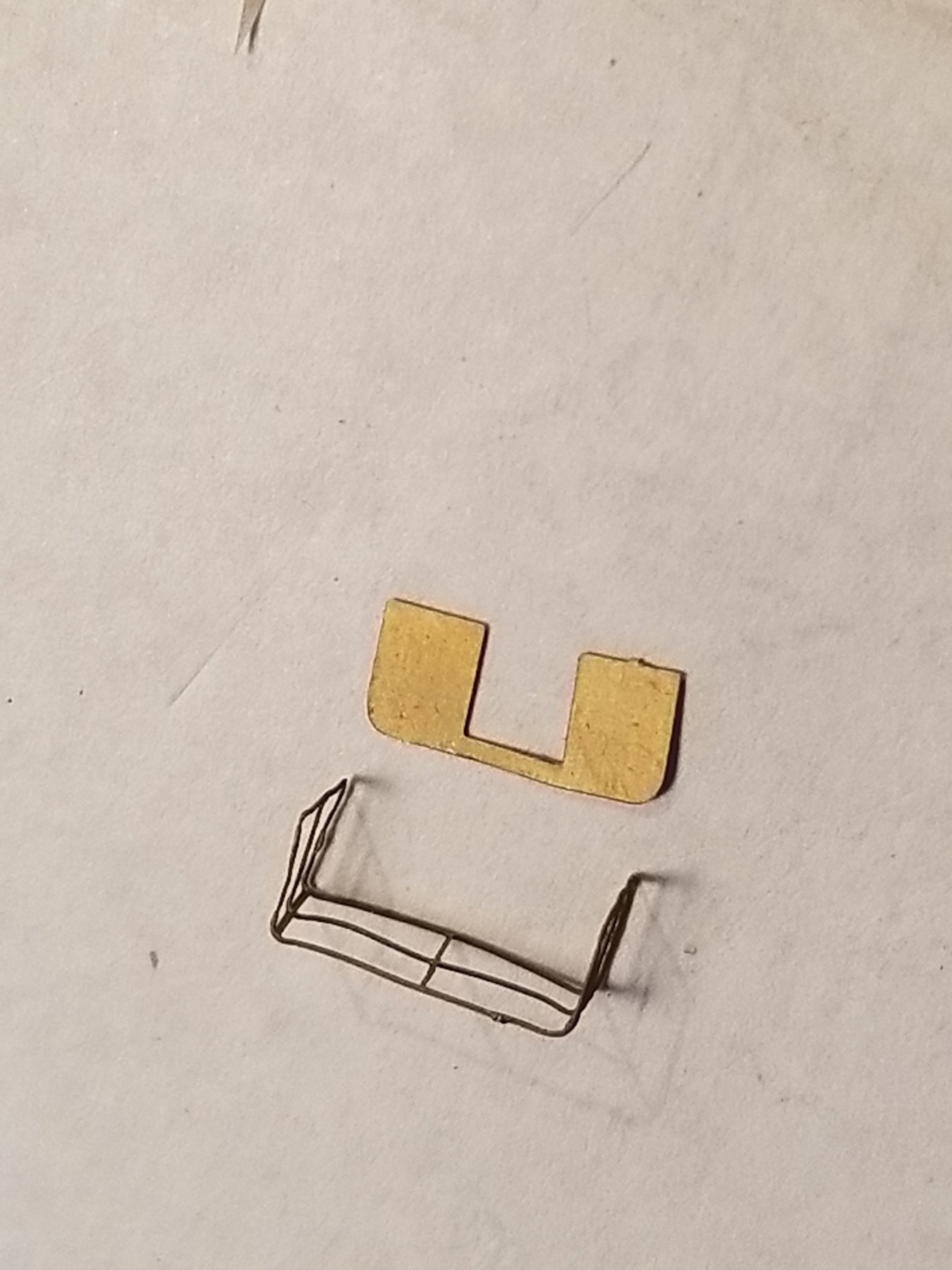
Thanks Carl and Denis for dropping by and your comments. Also my thanks to all who clicked the like button. Yeah Carl, a typical pick for a photo op. There always was either a non-com or an officers to "supervise" but actually to "motivate" the crew. That reminds me of what my father told us. A couple of Indonesian sailors were painting a part of the hull from a scaffold over the side. He caught them napping so he cut one rope and they fall into the water. Great commotion because most the Indonesians can't swim. So my father threw a life preserver to them. Today's post is for days 46, 47, 48 and 49 which brings us to February 22, 2018. After a late start I tried my modified drill bit in my mini drill motor and it worked just fine, almost no wobble. So I commenced drilling the two holes in the gun receiver. I diluted my thick CA to make it less globby and cemented both barrels into the holes. Next I cemented the crew seats to the platform and it to the plastic base. When the cement had cured I cemented the curved guide to the base and then the receiver with the barrels pointing skyward, scaring the Jap pilots - not. They cleverly stayed out of range. Day 47: Completed the first Bofors gun by cementing the gun sight to the receiver and the railing to the platform. This pretty much finishes the first gun and is ready for cleaning and paint. I figured to wait with straightening the railing out till after the assembly is painted. The material of the PE is rather soft and delicate, the slightest touch causes a distortion. Day 48: I was able to complete all four Bofors in the same method as my first one. They are now ready to be cleaned and painted but not today. Day 49: Cleaned the Bofors with enamel reducer, air dried them and painted with rattle can grey primer. After the primer had dried I painted all the Bofors with medium grey paint. Scraped some of the brown deck paint from the AA gun deck for the guns. Instead of using CA I mixed up some two part epoxy cement. I wanted some extra time to position the guns just so. Instead of pointing them all in the same direction I decided in different sections of the sky simulating the guns in individual firing mode. It looks rather sharp this way and I am happy with the results. Okay, we are now ready to start work on the 15 cm canons. Not today but tomorrow I hope. The gun barrels. At this magnification you can see the details clearly, quite well done. The receiver being drilled. The base. The center U shaped part is where the receiver will be cemented. The gun-sight. The crew platform and curved gun receiver guide cemented to the base with the rest of the parts to follow. The proto type Bofors assembled and ready for dressing, cleaning and painting. I'll wait till all four are completed. Four 40 mm Bofors guns. I staged them in different positions for an overall view. The railing is still in need of more adjustments. The Bofors cemented to the AA gun deck Overhead view. 40 mm shell boxes for the Bofors, photographed by Kevin Denlay. As previously explained Kevin is the first diver on Hr. Ms. Java's wreck. This location is on the AA gun deck. Cheers,

.thumb.jpg.f78603022bef0e0af3b311d133d77cd1.jpg)
.thumb.jpg.b966462bc6b83e49519c4483eb28e273.jpg)
.thumb.jpg.09667b5065e0da6e3caea2bd697d5a9a.jpg)
- 378 replies
-
- 8
-
-
- java
- pacific crossroads
- (and 2 more)
-
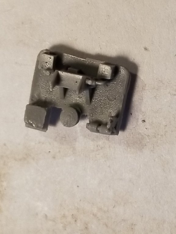
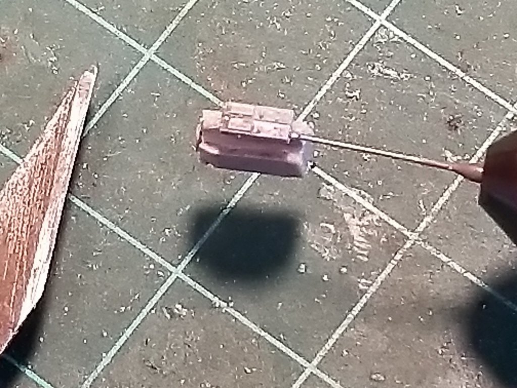
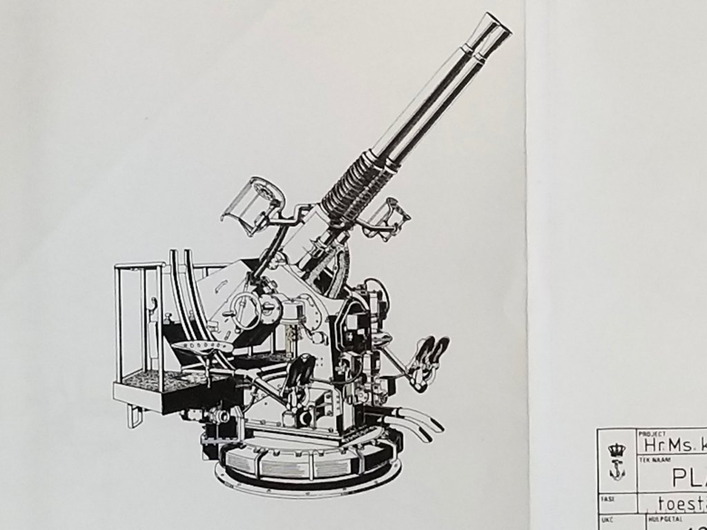
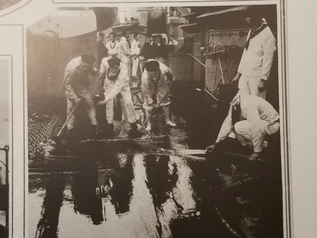
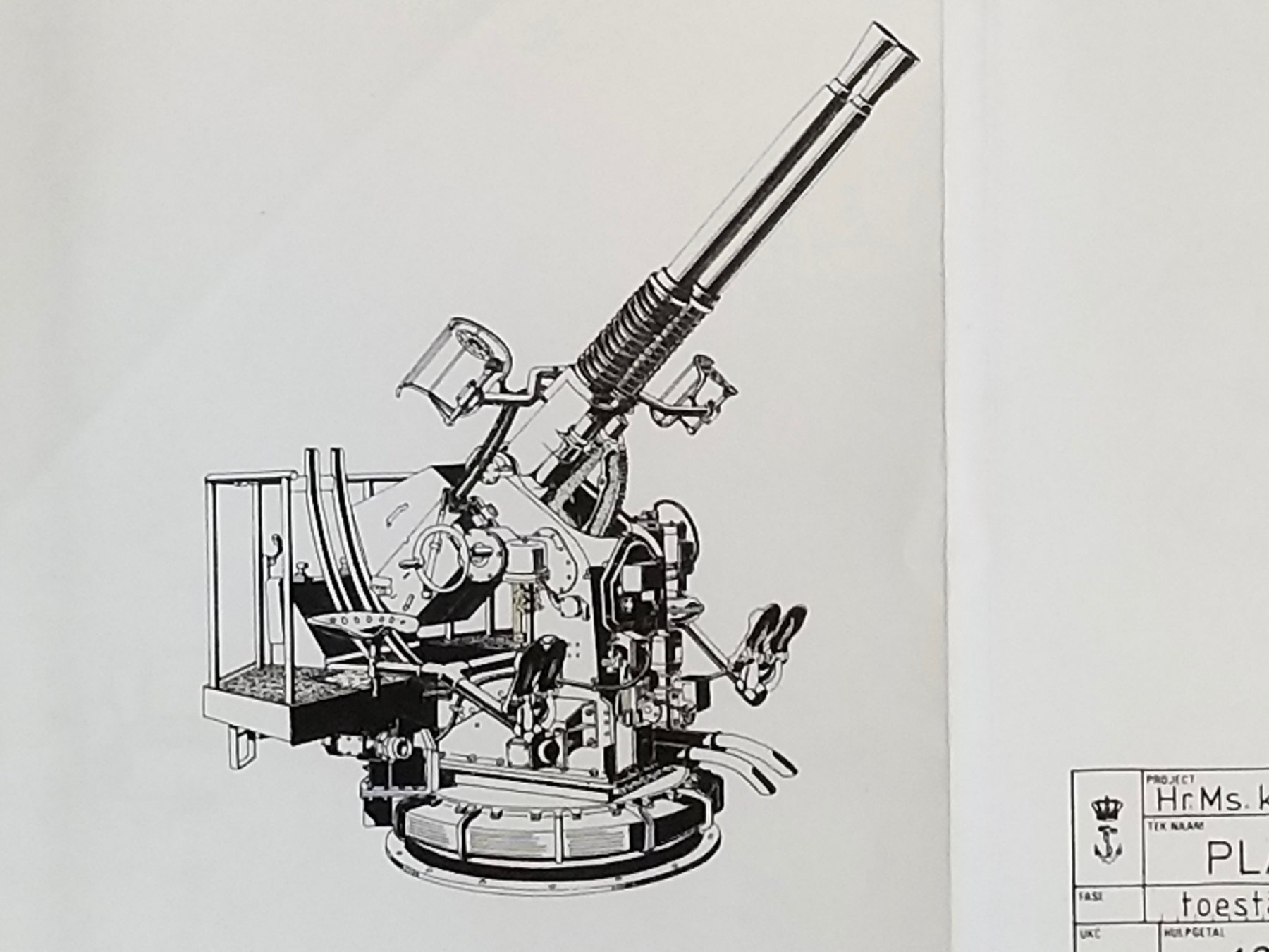
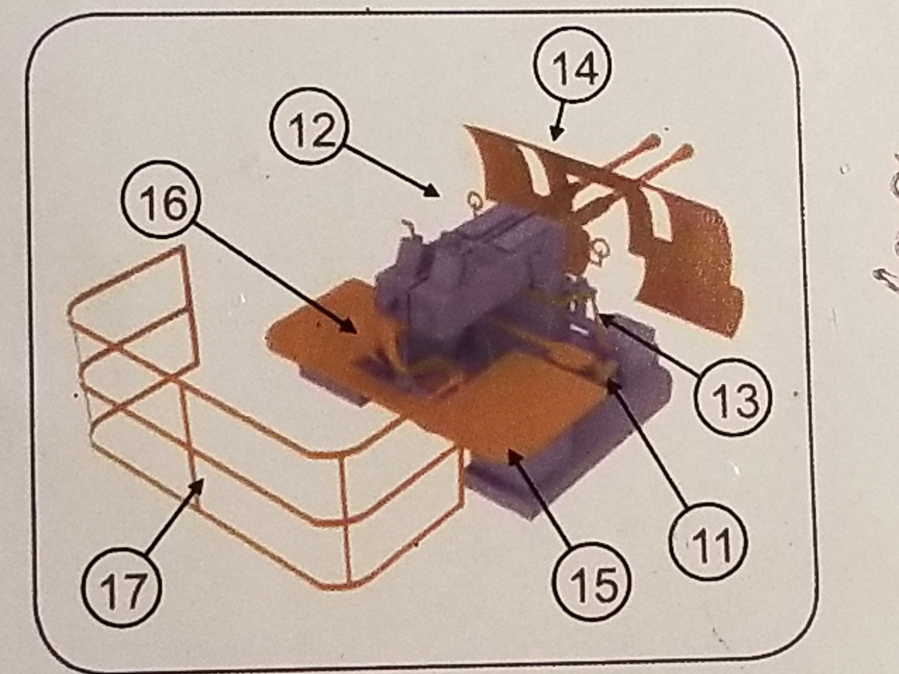
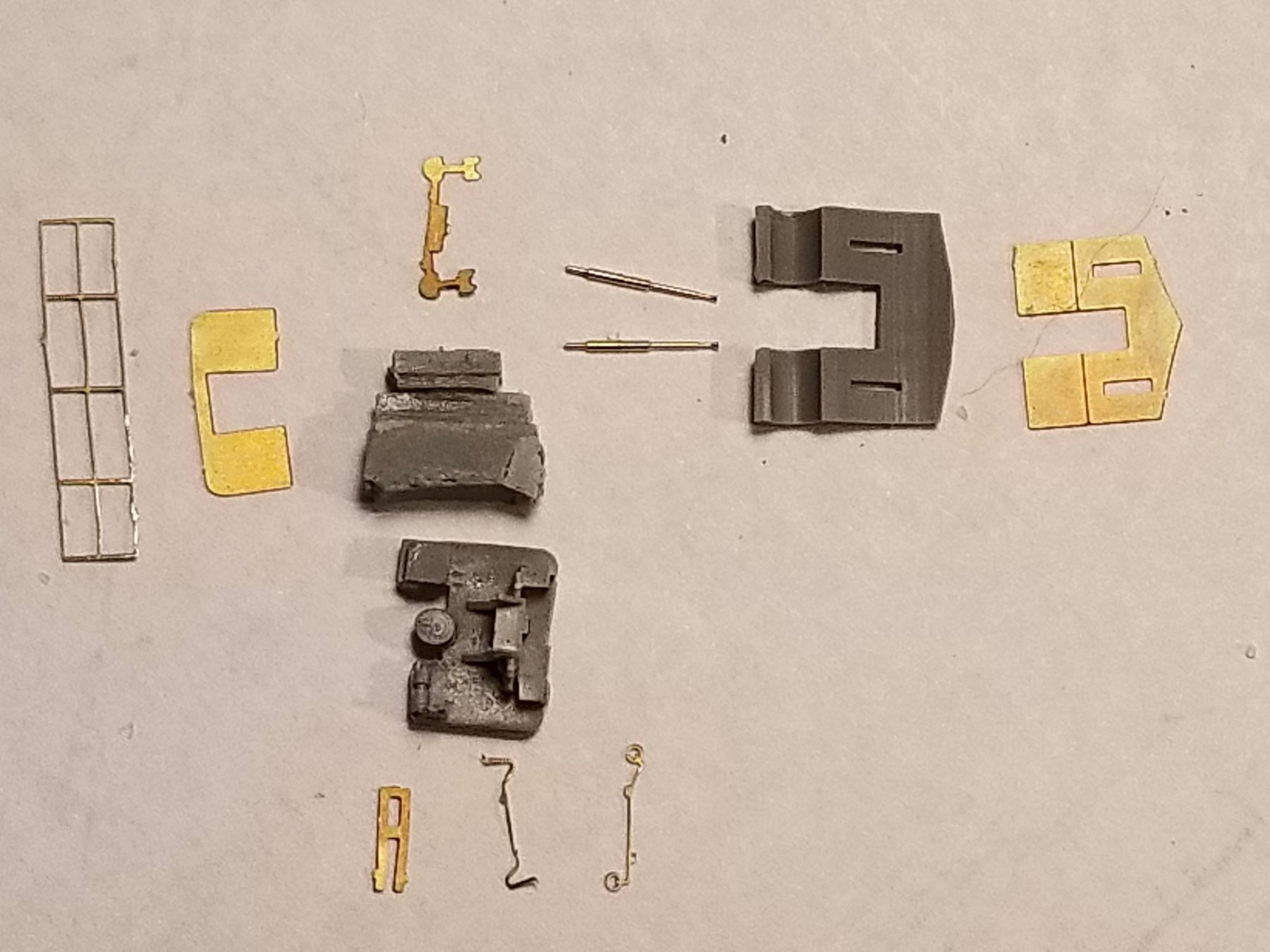
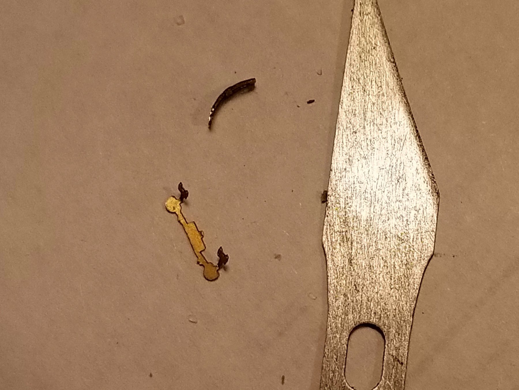
This post takes us to Day 45, February 18, 2018. This day I started with the assembly of the four 40 mm twin Bofors anti aircraft guns. Before I show and chat about the actual work I though giving you a little background history about how "Java" acquired these particular guns. At the end of WW I the British Vickers Company developed a revolutionary new gun that could fire several rounds per second. The sound of this rapid firing earned this gun the moniker "Pom-Pom." The idea was to lay a cloud of grenades in the air that made it a certainty of hitting an attacking airplane. This was good for that day because the airplanes were slow and flew low. It reminds of the flak idea used during WW II. England made these gun available to any nation who wanted them. Even the Japanese acquired them for a while for their heavy cruisers Nachi and Haguro. In 1937 the Royal Dutch Navy also acquired a set of six for the "Java" and "Sumatra," replacing the two 5.7 cm AA guns. The idea of "laying down a curtain of bullets" proved to be ineffective against the modern (for that day, 30s and 40s) aircraft and in 1938 both "Java" and "De Ruyter" replaced the Pom-poms with the 40 mm Bofors L.60 Hazemeyer-twin barrel AA guns. These are three-axis balanced to afford the gun freedom from the ship's movements and a steady aim on the target. They were centrally controlled via an analog "computer" of sorts but could also be independently fire at will. These guns were the state of the art at that time. I will depict my model in the independent controlled state. They could fire two rounds per second. As good as these guns were there are a few disadvantages as well. !. the central control system. If damaged or failed it became a handicap and the guns must resort to manual control. "De Ruyter" experienced such an event during the battle in the Bali Sea earlier in February of 1942. A piece of shrapnel from a near miss of a Japanese bomb knocked it out. 2. Placing all four of these guns in one central location prevented forward firing due to the placement of the smoke stacks and masts. 3. The placement around the ammo supply tubes. This connected the AA deck with the aft ammunition magazine below it. This proved fatal when the Japanese torpedo hit the magazine. Fire and exploding shells came up the supply tube and caused heavy damage and death of the gun crews. 4. Enterprising attacking aircraft learned to rake the AA deck with great success. 5. With a central control system only one target could be aimed at, which hints at the old "cloud barrage" idea. So then, having said all that we'll now commence with the build. First order of business was to assemble all the parts for one gun that I'll use as a prototype. I will omit the shield in front of the gun because none of my photos show this installed on "Java." I will also try to cement the receiver with barrels pointing skyward. In order to cement the barrels into the receiver I have to drill holes in the respective spots, next to each other. Measuring the machined end of the gun barrels I selected a #85 drill bit. The problem is that it as way too small for the smallest collet for my pencil drill motor. My Proxxon drill motor could be used but a little bulky and less control because I have to hold the receiver in my left hand and handle the drill motor with the right. So, I mixed some epoxy cement and dabbed it around the drill shank and let it harden up. I'll later smooth it out some to fit the collet. Next I pre-bend the aft railing and the receiver guide This is all I could do today. Hopefully more tomorrow. The AA gun deck with the four Bofors guns, looking forward. Here you can see the forward firing obstructions of the masts and funnels. This picture shows that the AA gun deck has a railing. The kit instructions show no railing and I'll go with that. It does have a raised side though. The specific Bofors twin barrel gun on "Java." A copy of the installation guide for the Bofors gun. #24 not used; #12 manual eye sight; #11 seat/foot rest; #15 crew platform; #16 receiver guide; #17 railing. I'll try to cement the lower railing rod to the edge of the platform. Here are all pertinent parts laid out. The receiver is still attached to it's mold base and the part below it is the actual base. You can make out where the receiver is to be cemented to. Fortunately I don't have to modify it to cement the gun pointing up. At the ends of each barrel you can see the machined pins that'll be cemented into the receiver. That A looking thingy is the receiver guide that'll be curved. Next to it is the hand crank for moving the receiver up or down, I think. Above the receiver is the seat and footrest. The barrels actually have the recoil springs machined into them, really good. The "Java" crew in action during a gun drill. A 5 man crew for each gun. You can see that no shield is used. There usually was a senior non-com or an officer on deck. My modified drill bit, waiting for the epoxy to harden. A little filing and it should work. The pre-bend railing, all the unevenness and wrinkles I'll try to straighten out as much as possible after it's cemented to the platform. This PE is very soft and the slightest touch moves it out of shape. Not easy to work with. The gun-sight. Cheers,
_copy.thumb.jpg.364d1c5bcc3cec29615d361a096327da.jpg)


_copy.jpg.bae0c3be700ef0b2936af97cced40430.jpg)


.thumb.jpg.6f6711e424b7e4003f50ab00f17170b1.jpg)
- 378 replies
-
- 9
-
-
- java
- pacific crossroads
- (and 2 more)
-
Thank you Lawrence, Denis and John for for your very kind words, it's much appreciated. Here is a picture for Carl. He was mentioning "holy stoning" the deck, well here are a bunch of Dutch swabbies doing just that. A copy from my book "Hr. Ms. Hruisers "Java" en "Sumatra" by J. Anten, 2001. Cheers,
- 378 replies
-
- 6
-
-
- java
- pacific crossroads
- (and 2 more)
-
Well KP, your effort certainly came out rather well. That type of sub was very advanced in design and capability. Hey Denis, I didn't know there is such a kit out of the Gato class US subs. I would not mind putting one together and model it after the USS Cod. That's the US sub that rescued the crew from my father's sub the O19 in 1945. The Cod is well preserved in Cleveland, Ohio and the Museum director told me she's 98% sea worthy. I could pair that model next to the O19 I build a few ago. You made me think again my friend. Cheers,
-
Well JesseLee at least you have a serving machine, I do not. Rickety or not it serves the purpose - pun intended A nifty dead eye spacing tool you made my friend and your shrouds look really nice. Cheers,
- 1,306 replies
-
- 7
-
-
- syren
- model shipways
- (and 1 more)
-
Nice work Kevin. Cheers,
-
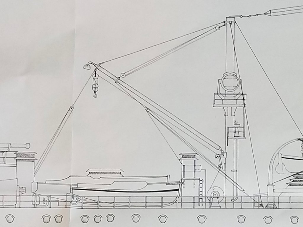
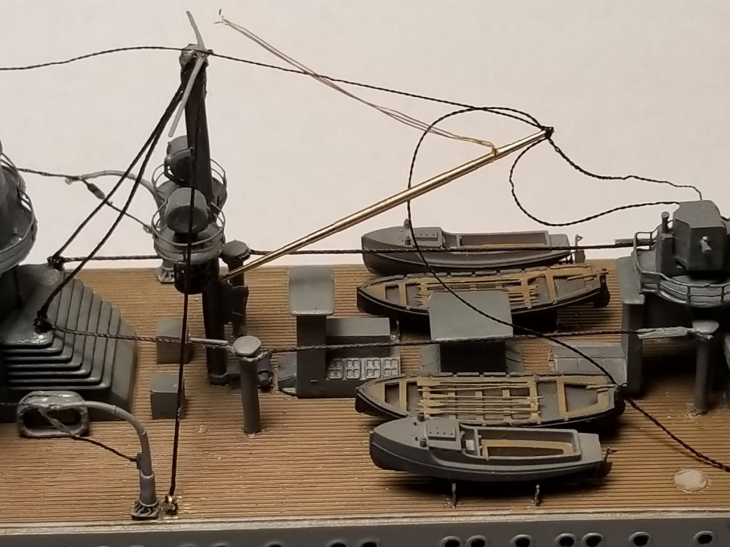
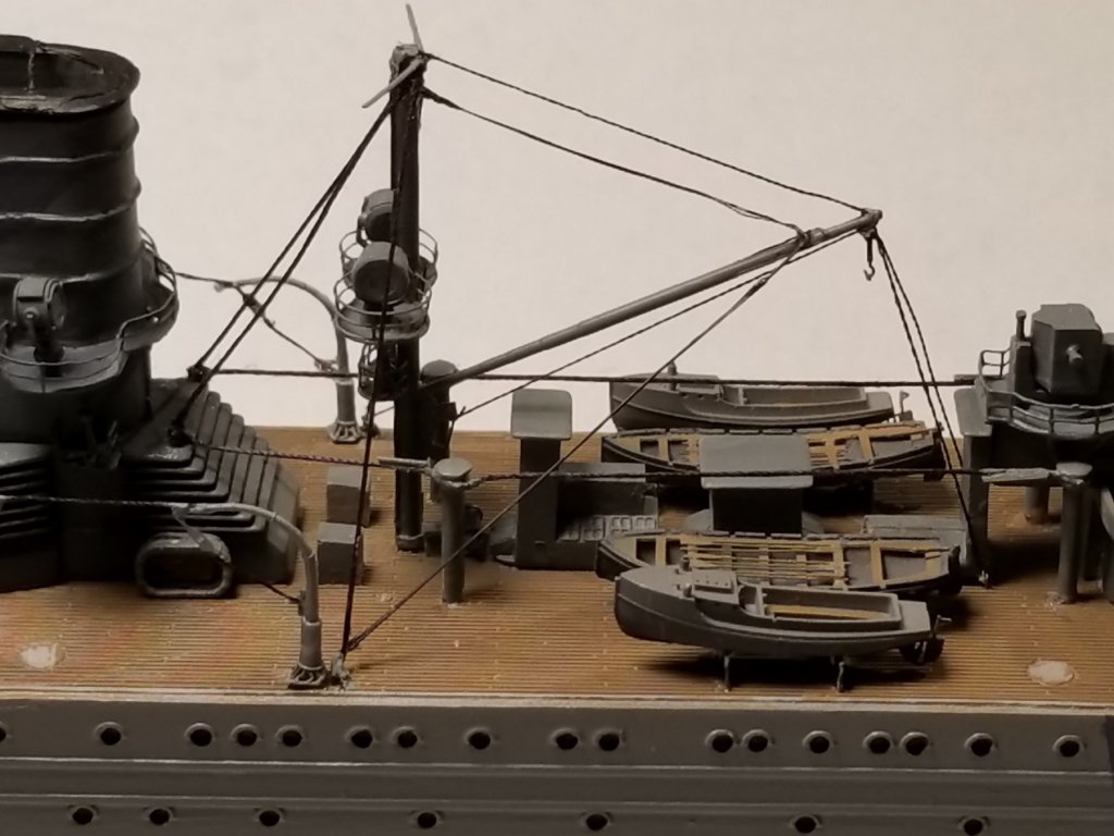
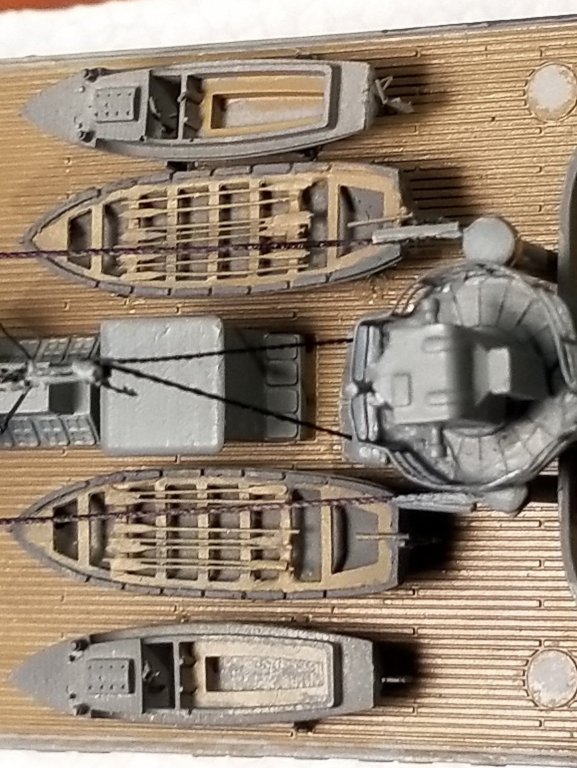
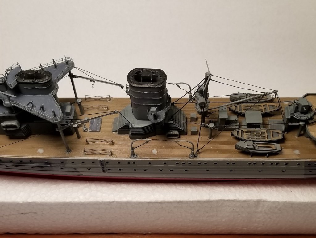
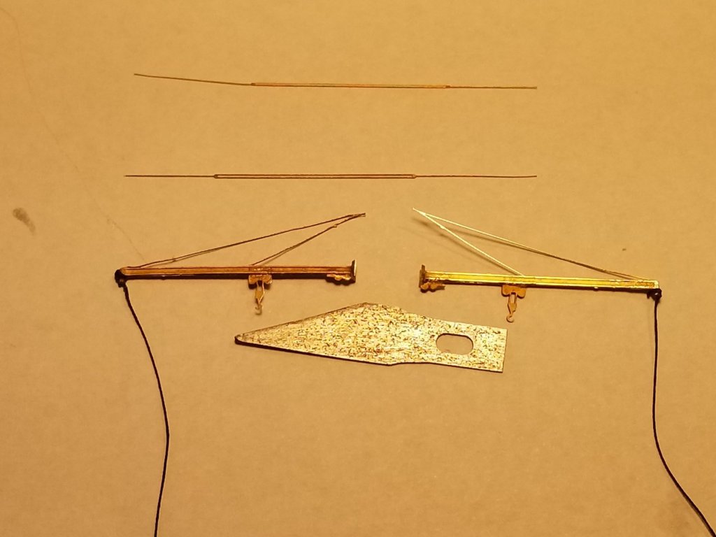
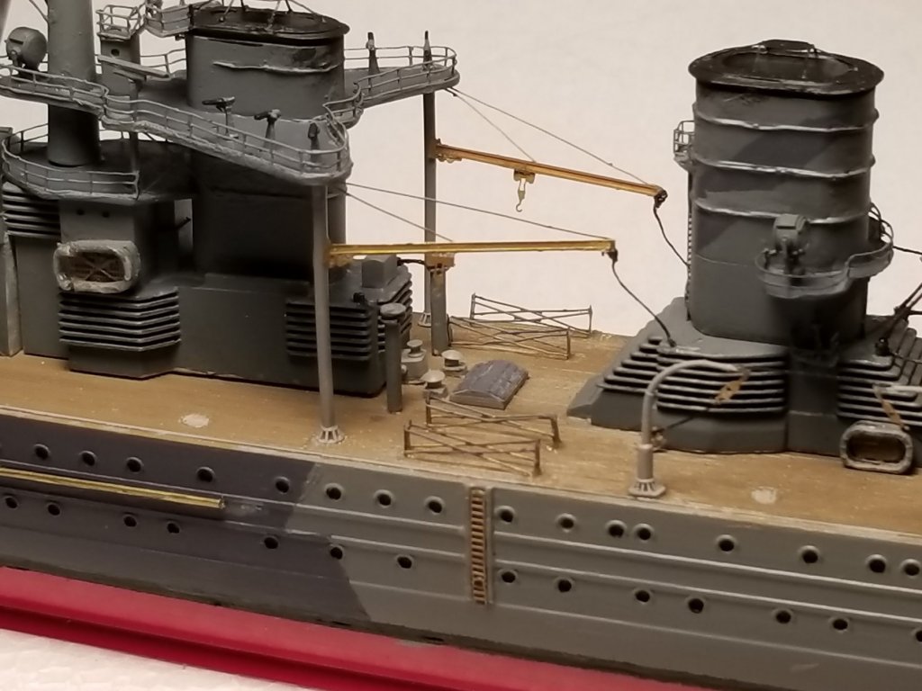
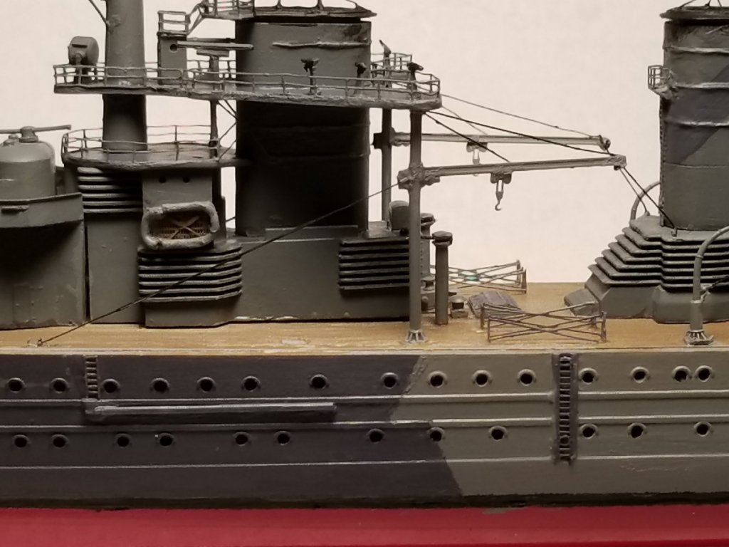
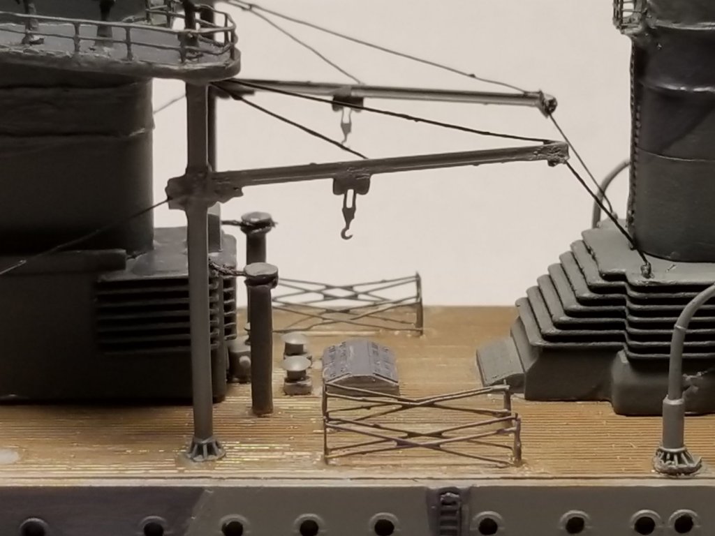
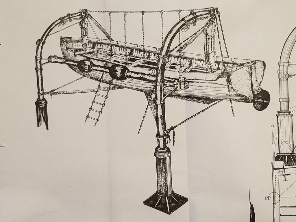
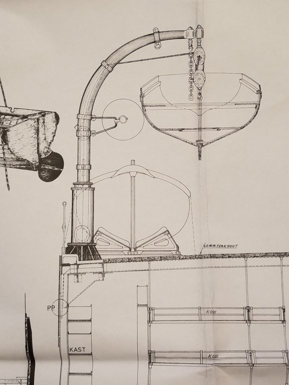
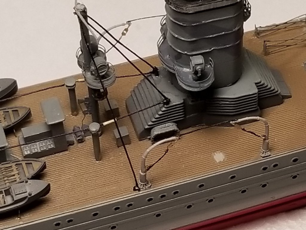
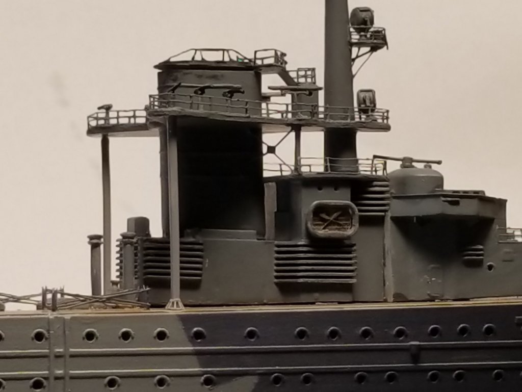
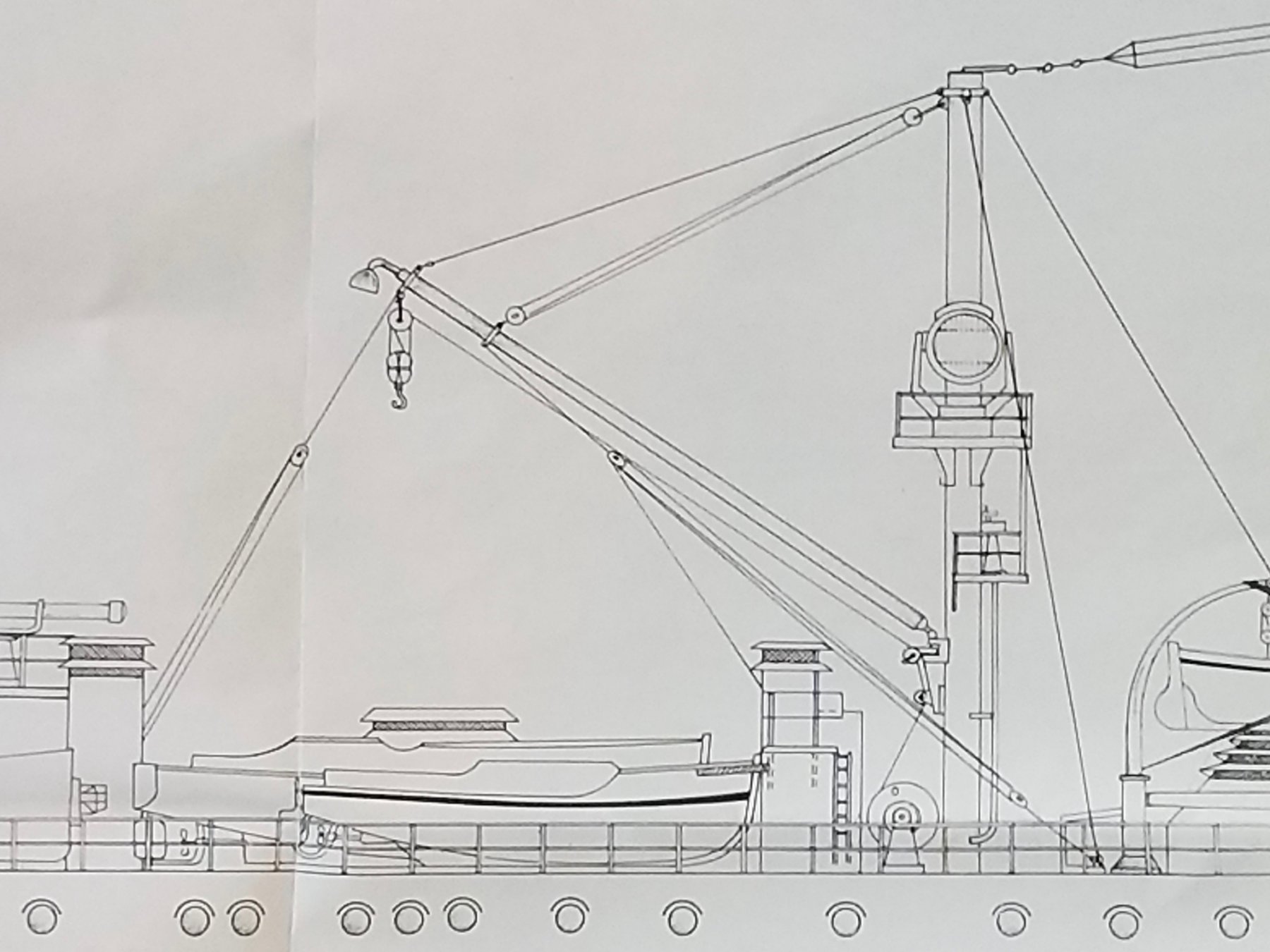
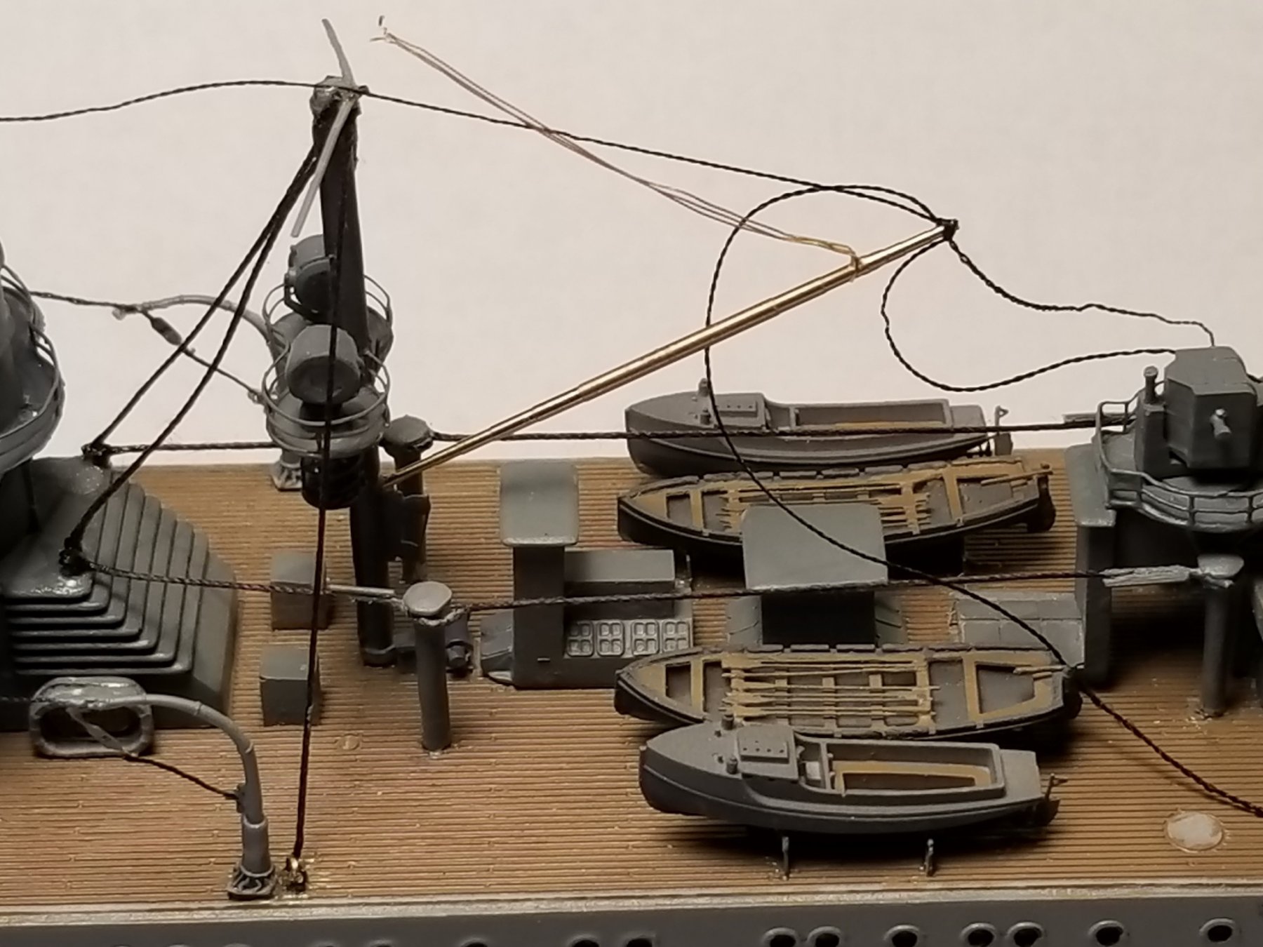
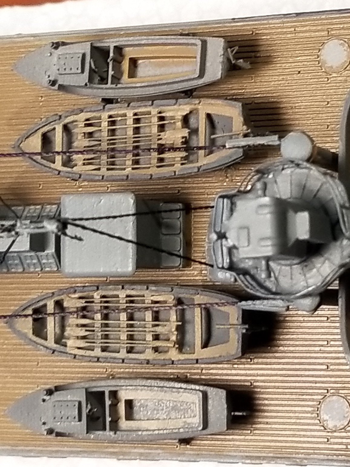
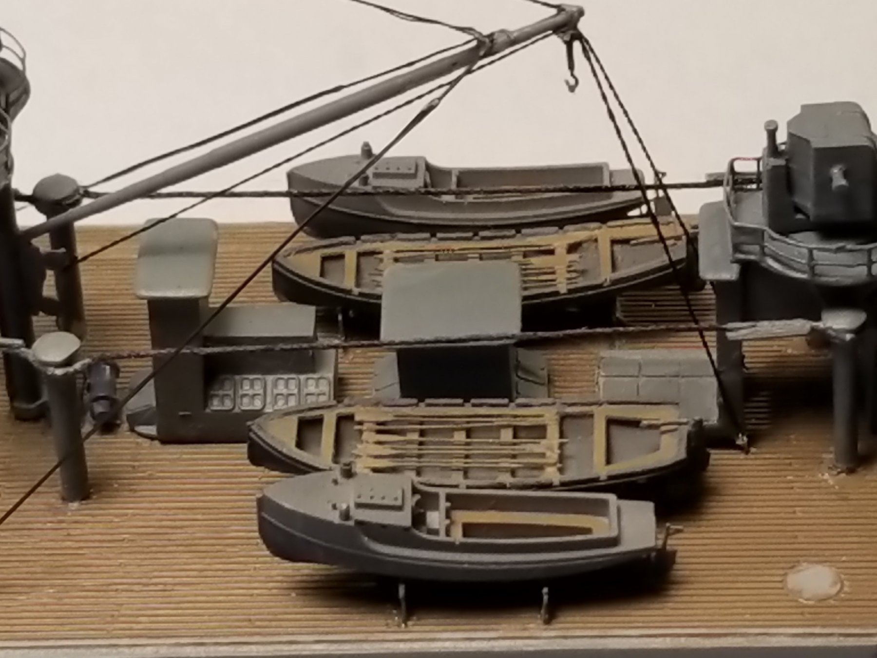
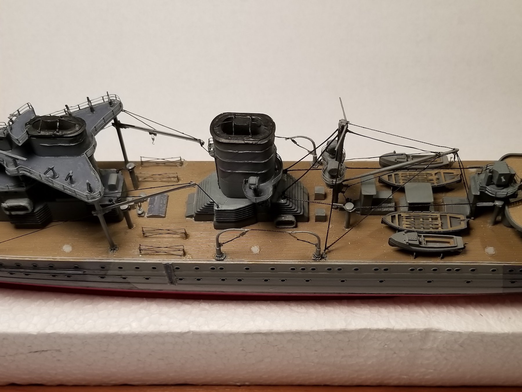
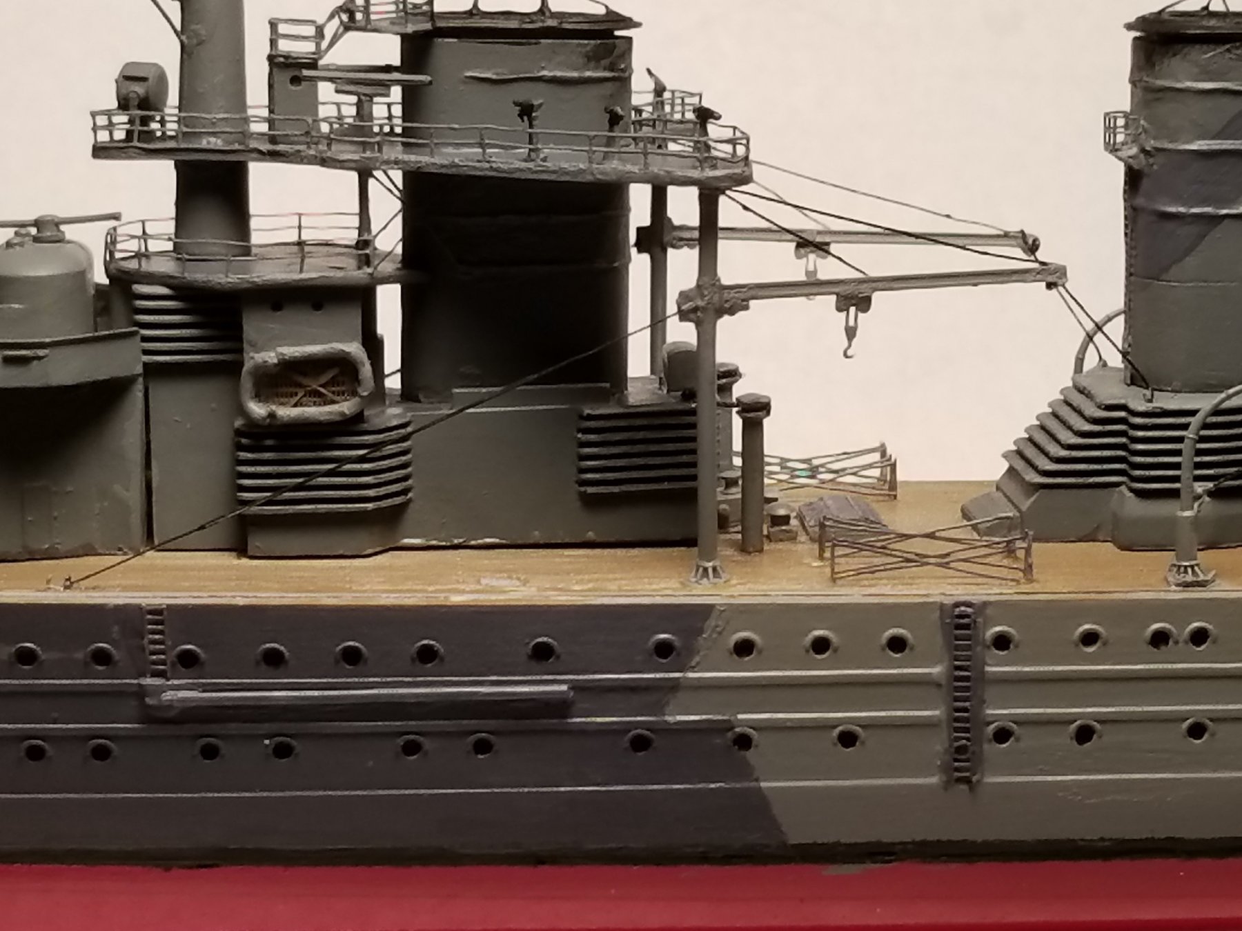
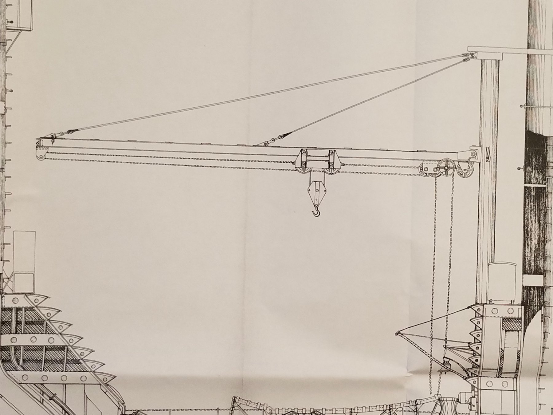
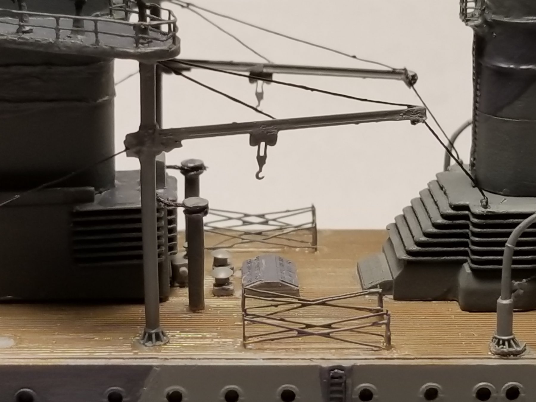
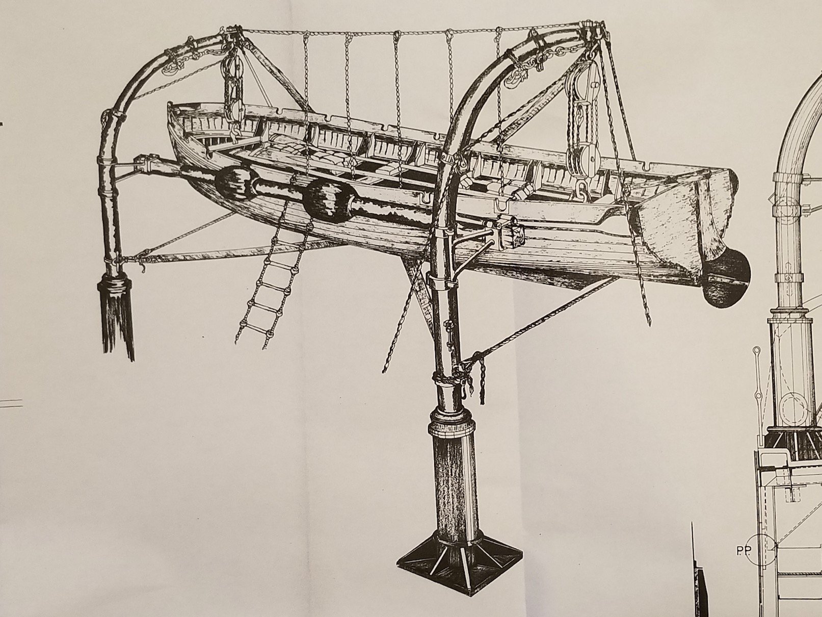
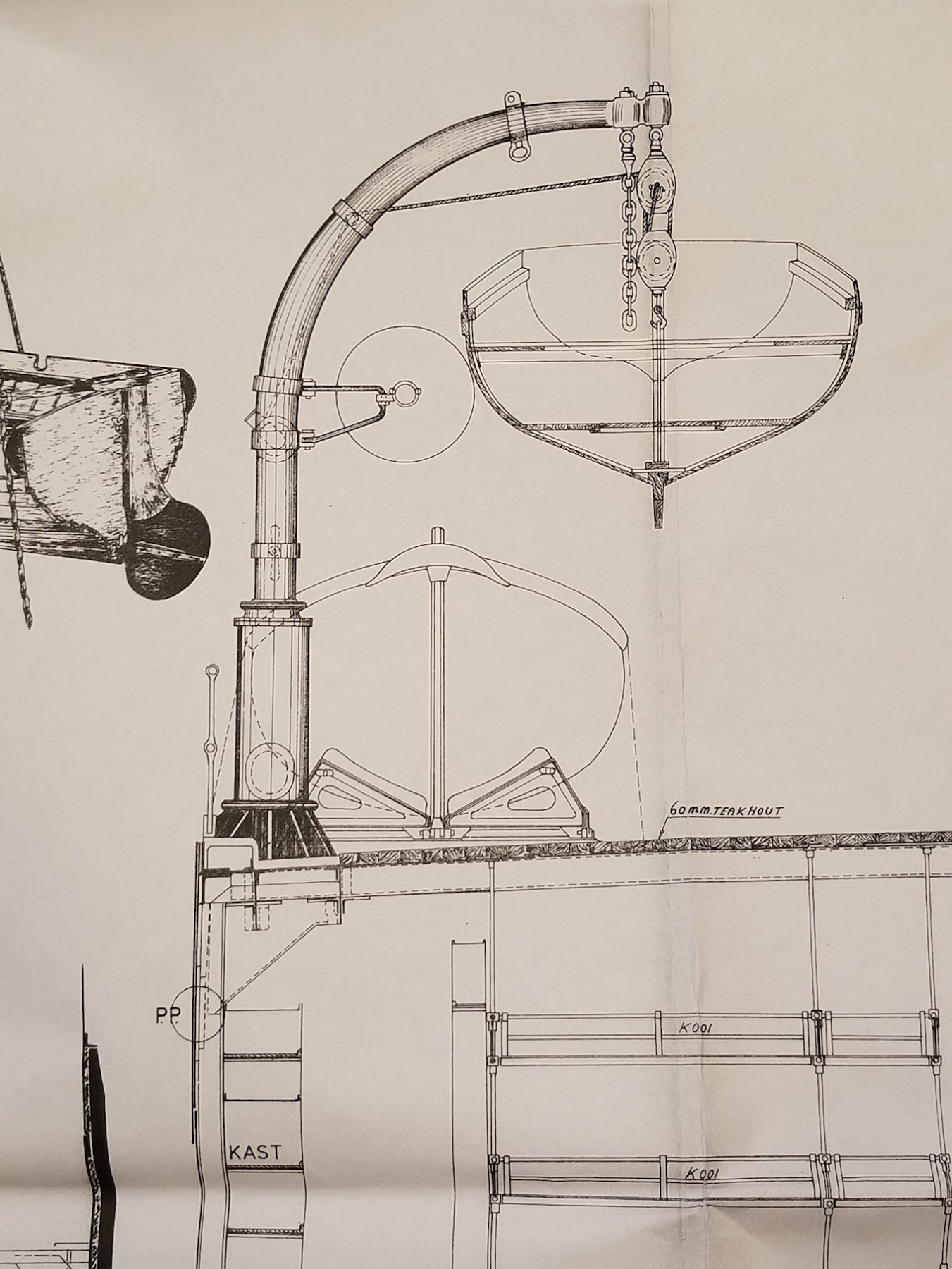
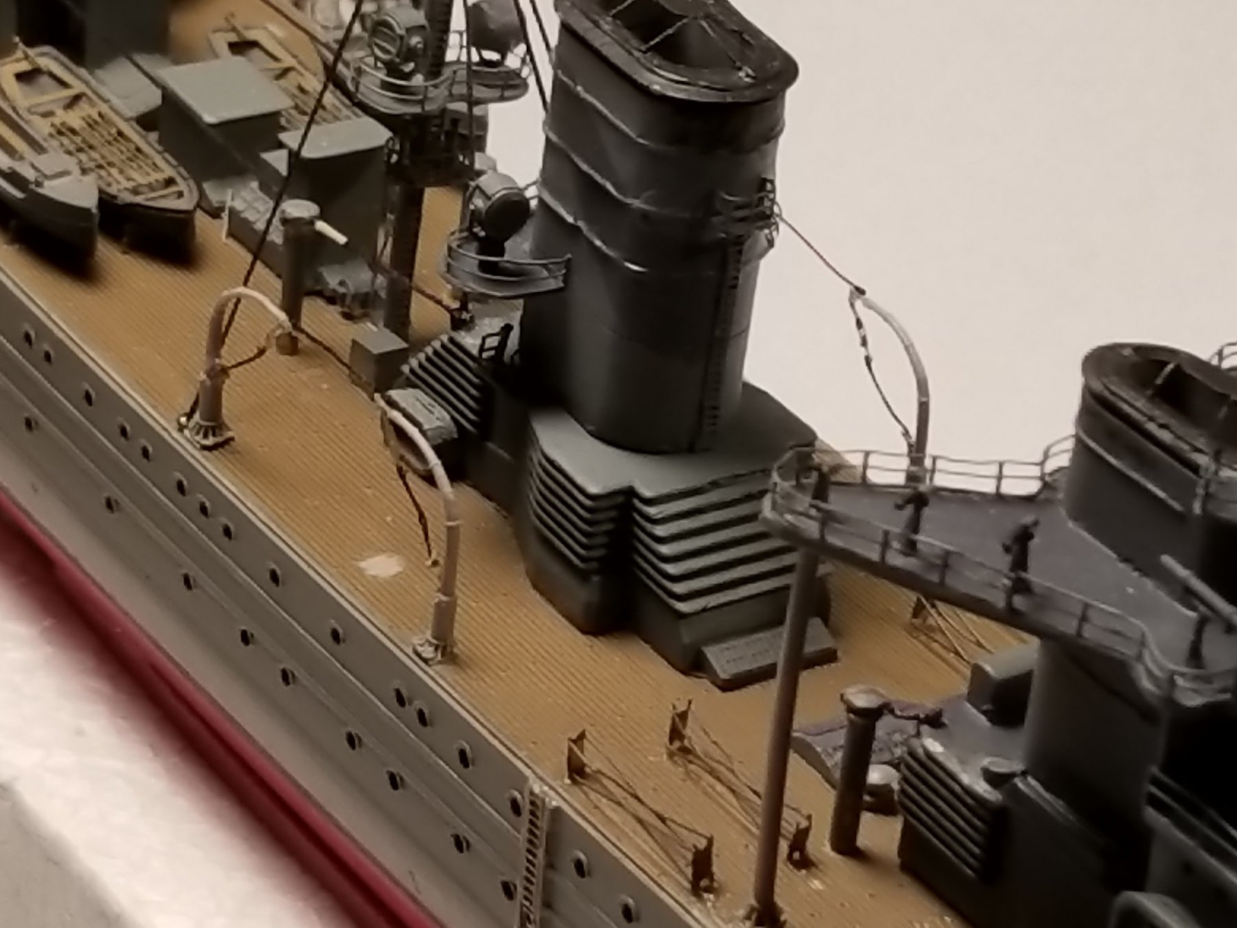
Thank you Denis and Carl. Hey Carl, I have never used this holy stone but a lot of polishing compound on airplanes though, does that count?? Okay, we are now at day 44, which brings us to January 29, 2018. I finally tackled that difficult job, the ship's boats loading and unloading boom. Before cementing the boom to the mast I started with cementing the top most static support cable and the lifting/lowering pulley tackle rig. Then cemented the hook cable from the front of the boom with a piece of silk tread. I'll attach it later to the motor driven winch. I did not have the PE cable assembly that runs from the end of the boom to the deck. Instead I used two silk threads for this that will be fastened to scratch build eyelets on the deck next to the aft vent pipes. This will be done after the boom is cemented to the deck. The PE boom swing tackle and hook will also be cemented on after the boom is secured to the mast. They will be fastened to the same eyelets for the mast side stays. It was now time to cement the boom to the mast, which proceeded rather well in spite of all these loose pieces of rigging. Next came the task to secure all the loose cables and ropes to their assigned places. It was now also time to paint everything in medium grey except the cabling is dome in dark grey. Here I thought this was going to be a real challenge but it went surprisingly rather quick. Next up will be assembling the 4 Bofors. I'll have to kit-bash these because I want to have the barrels pointing skyward attempting tho get the Japanese observation planes but these clever guys kept out of range. This is a copy from my 1:50 scale scratch build drawing. It shows how everything runs from here to there. This shows the boom cemented to the mast with all the loose rigging. Here the installation is completed and painted. A bird's eye view of the boat deck. A close-up view of the boom and ship's boats. Overall view of the jobs completed in the last few days. Cheers,

- 378 replies
-
- 10
-
-
- java
- pacific crossroads
- (and 2 more)
-
Looking very nice JesseLee and now the rat lines. Cheers,
- 1,306 replies
-
- 4
-
-
- syren
- model shipways
- (and 1 more)
-
Looks like you have a plan and some nice guidance drawings. That kinda stuff is the interesting part of scratch building and a lot of fun. Cheers,
-
Ah yes, Dutch ingenuity, tape around the cannon to secure it in place. She's looking great Hennie. Cheers,
- 192 replies
-
- 3
-
-
- sovereign of the seas
- sergal
- (and 1 more)
-
Some nice metal work Kevin, it looks real. Cheers,
-
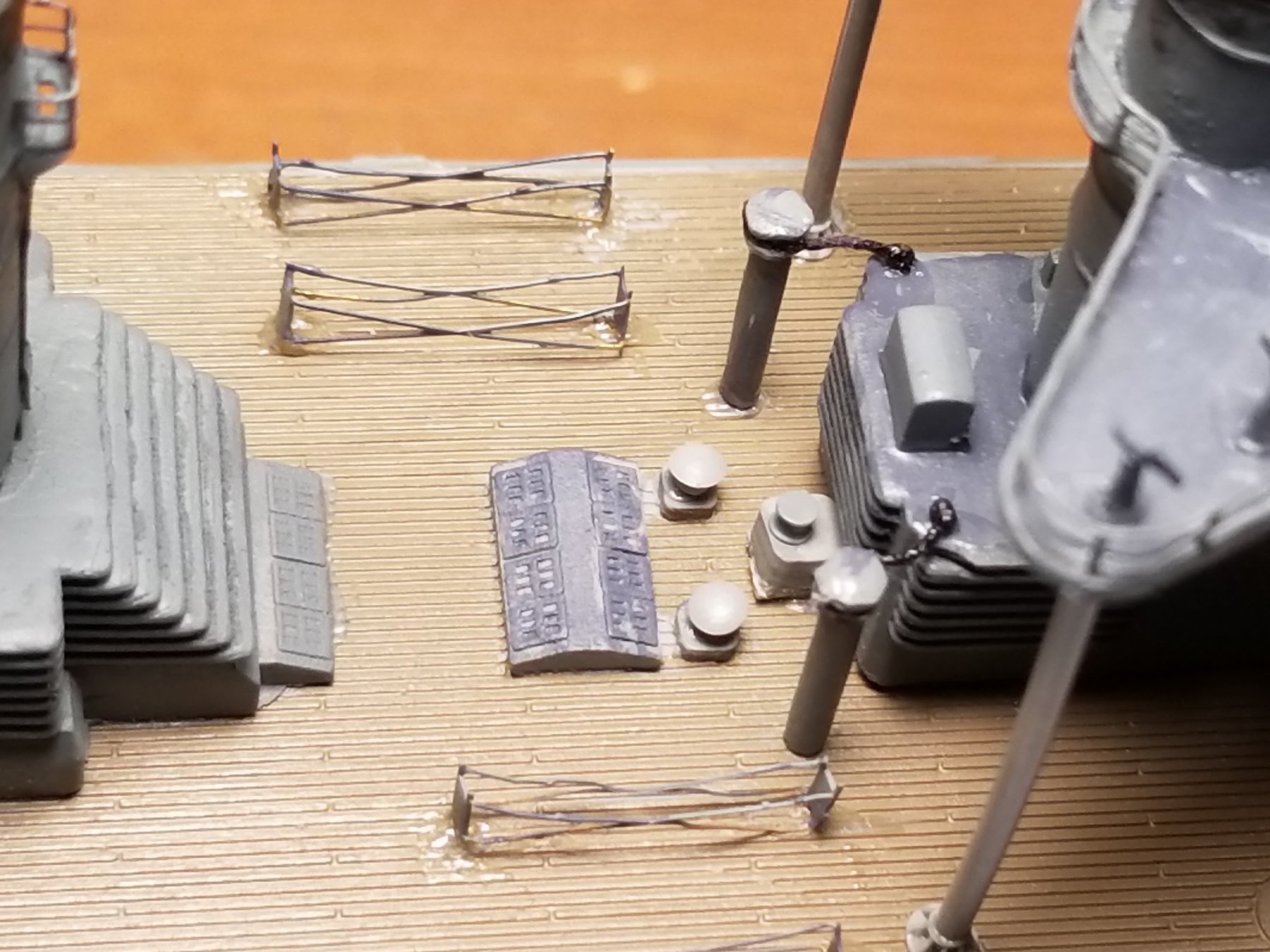
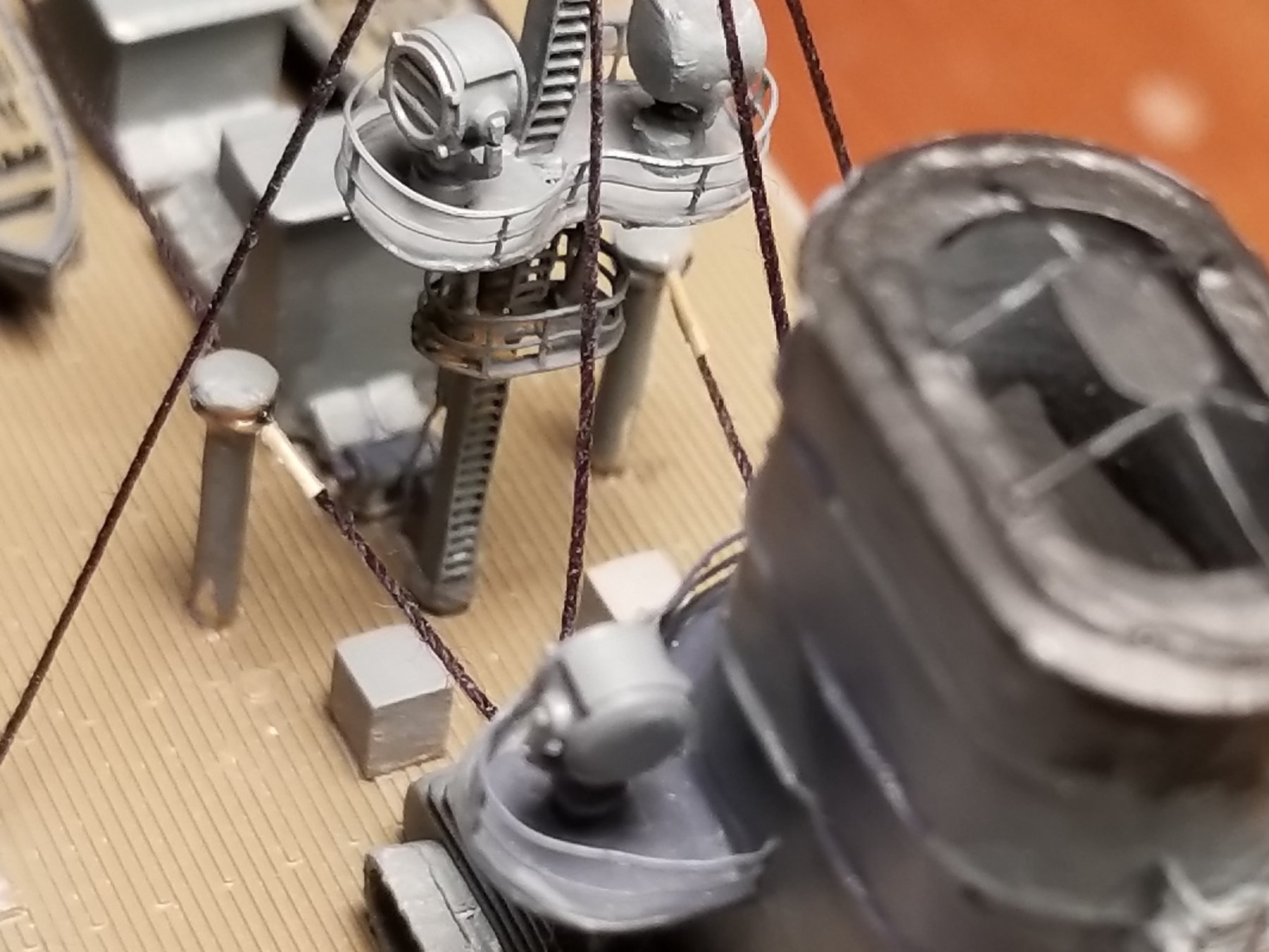
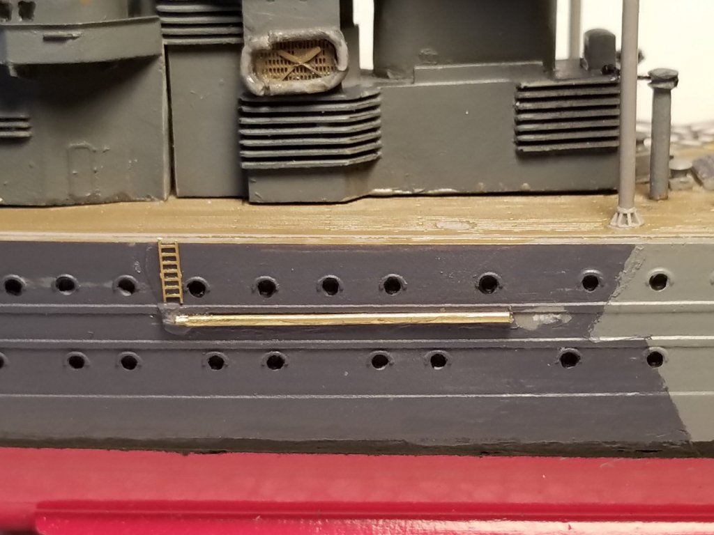
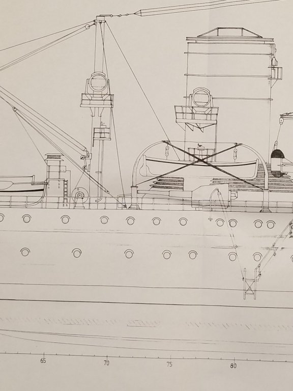
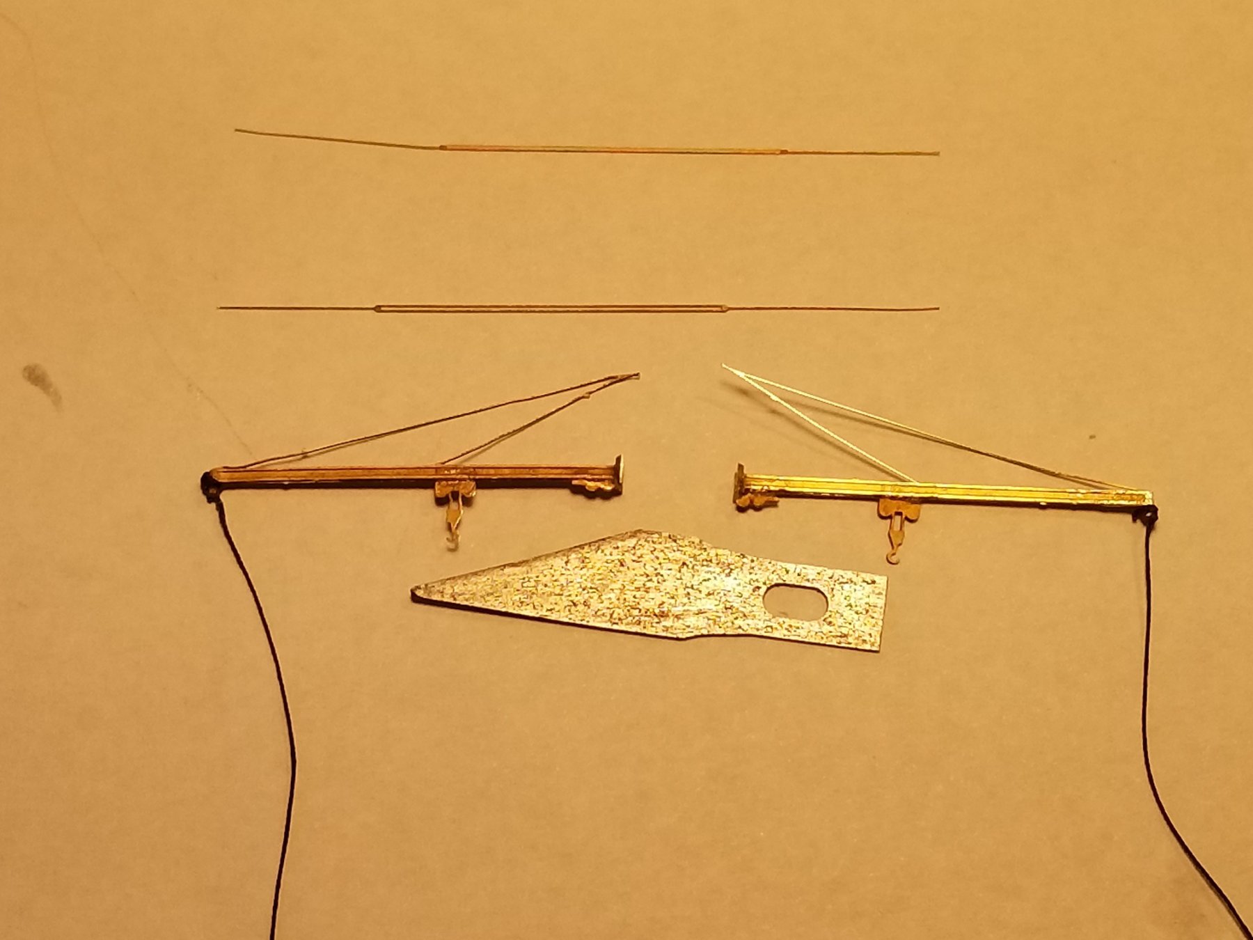
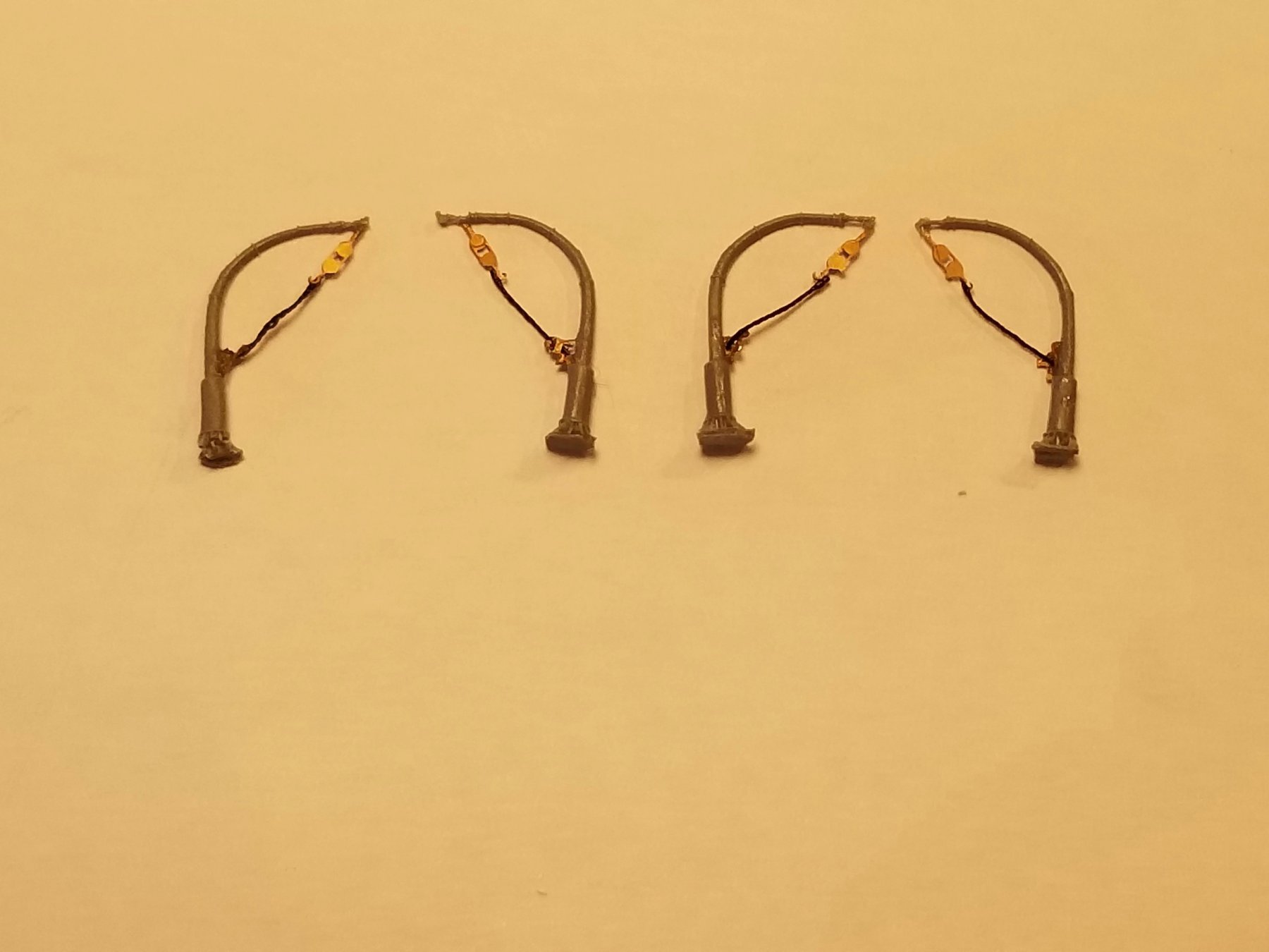
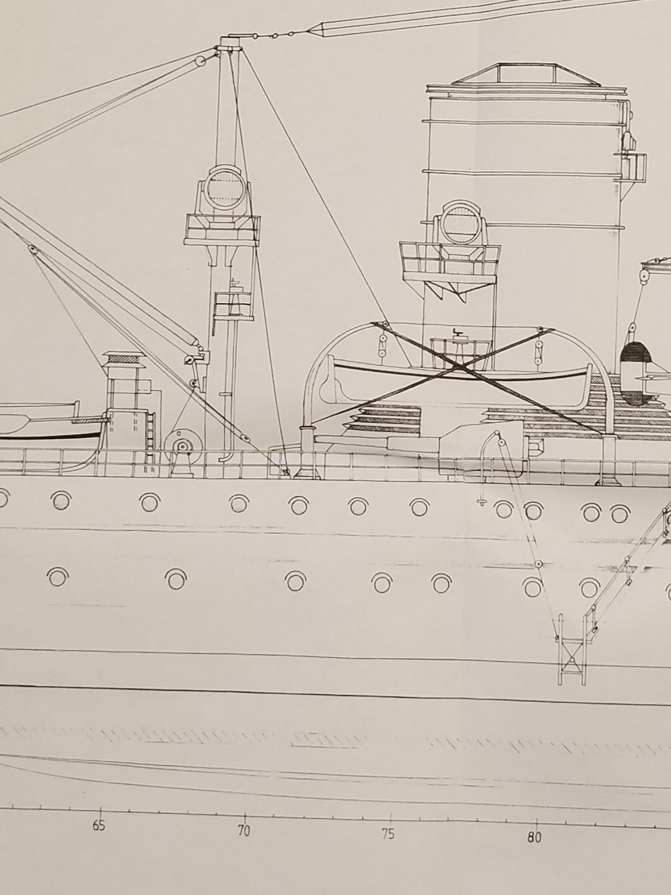
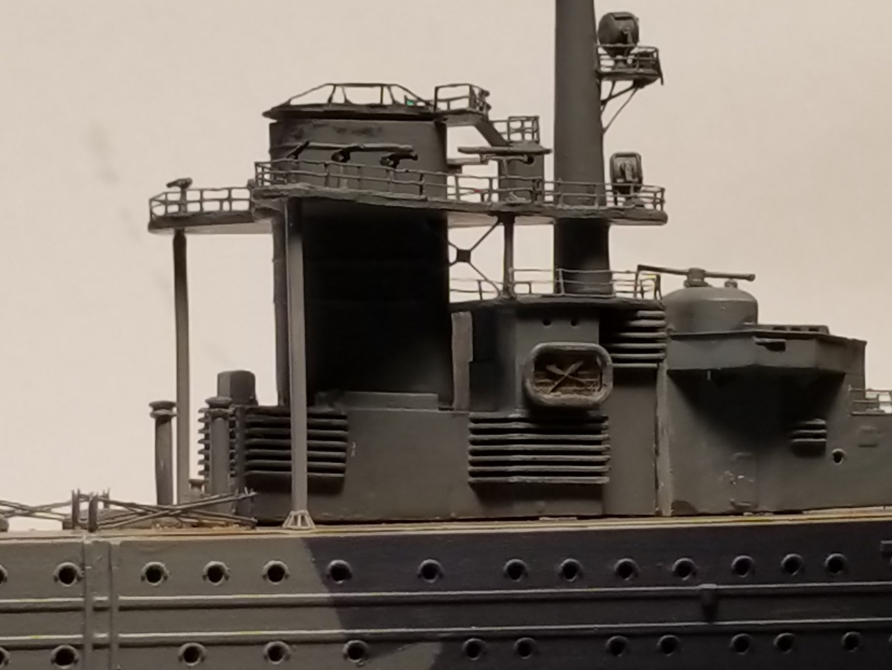
Thanks Carl, yeas, she's slowly progressing. I am very close to getting to the current date. A few more installments. Currently I am still occupied with most in-house chores like cooking, dish-washing, floor scrubbing etc. besides the never ending yard work. Gwen's hand is healing very nicely and can now straighten all her fingers out without them locking up. Still some discomfort when making a fist though, which is a good thing - - for me Okay then, today's post is for days 41, 42 and 43, which brings us to January 29, 2018. On day 41 I started with assembling the seaplane loading/unloading gantries. First was removing them from the PE sheet with their associated PE parts. The gantry boom is etched in one piece and had to be folded double to make the complete beam. Another sticky job in not damaging the support cables that are part of the whole. Once I had them perfectly aligned I used a drop of CA to keep them together, Next was cementing the traveling hook and pulley assembly for at the end and cemented them to the beam. I added a few strands of silk thread to the ends of the beams to simulate the mooring ropes, preventing the beams from swinging. These ropes will be fastened to the top of the rear funnel vent housing. On day 42 I cut two small pieces of brass rod to simulate the observation plane refueling supply pipes at the sides of the hull and cemented them into place. Yeah, I had to scrape away some paint but I'll touch it up later. there is a lot of touch-up work to do anyhow. Looking at the 1:50 scale scratch build drawings there is a ladder from the deck down to the pivot part of the pipe so I got a piece from my spare PE and cemented that to the hull. My guess is for access to that point for the crew to attach the fuel hose and unlatch the pipe. There is also a gantry from the deck to the end of the pipe but I'll wait with cementing that on when I install the railing. After lunch I installed both the aircraft loading gantries and started with the forward support stays. To simulate them being fastened to the deck I made two cleats and cemented them to the deck. No time to install the stays. On day 43 I cemented both front stays. Them being from extremely thin PE it was a rather delicate operation but turned out rather good. Next I painted all the installed PE and some touch-up work. A copy of my 1:50 scale drawing showing the aircraft loading gantry installation. This would be a rather fun project to tackle if I ever have the time to do so. These are the main parts for the gantries. I have placed my Exacto #11 blade in te picture to give you an idea of size. I did not attempt to add the chains to the traveling hook assembly. I guess I could have used one of my hears - - - This shows bothe gantries installed. Both the securing ropes will be replaced. Both stays are installed and the securing ropes replaced, now they are taut. I guess You can also see the cleats I made for the stay. Another look at the finished gantry installation. This is that aircraft refueling pipe arrangement. That little bump below the ladder is a hinge assembly to allow the boom to swing out. Ah yes, I goofed on the ladder, that'll be straightened out before long and painted of course. According the drawings I have there is a rope attached to the pivot support brace at the end of this pipe to the ladder serving as a handhold. Seems rather tricky to walk across that pipe with the ship pitching. Painted with some touch-ups.

.thumb.jpg.5c766ef0e4969c8422826c76e3e14fff.jpg)
- 378 replies
-
- 11
-
-
- java
- pacific crossroads
- (and 2 more)
-
Great start Hartmut. Nice large scale for all the detail you'll be putting on the ship, as I suspect you will. Yes, a rather unorthodox way prepping the hull for planking but you are right in that it will make a very stable and strong model. Safe me a seat up front, okay. Cheers,
-
A very fine looking model Marcus. About the flags, Several paintings I have seen of the jachten have a large Dutch standard with the shield of the city or company in the center white band at the stern flag pole. The jib carries a smaller Dutch flag and a red, white and blue pennon (wimpel) at the top of the mast and sometimes on the gaff. To get the shield of the City of Utrecht in the white band of the flag may be too difficult to achieve at this scale. An artist, Walter Otte van Soest, made a painting of the Statenjacht Utrecht in 2004 where he shows the flag of the City Utrecht at the stern with the Dutch flag at the jib and a small Dutch flag at the top of the mast. Either way you go it will still be a magnificent model. Cheers,
- 305 replies
-
- 4
-
-
- utrecht
- statenjacht
- (and 1 more)
-
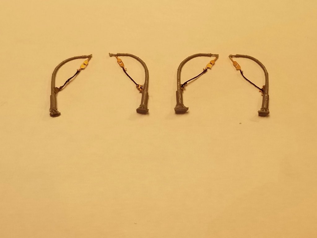
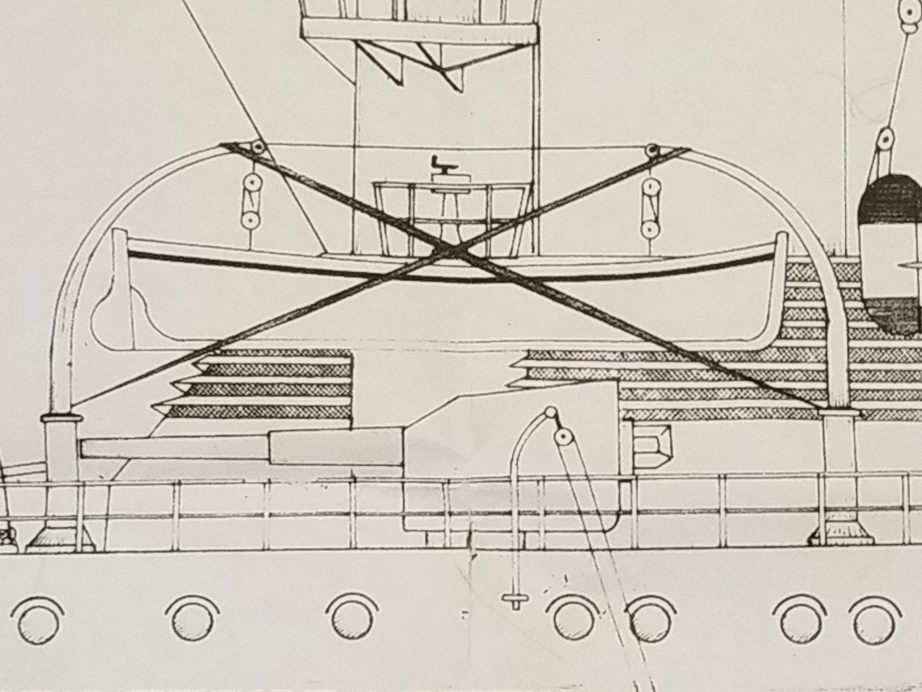
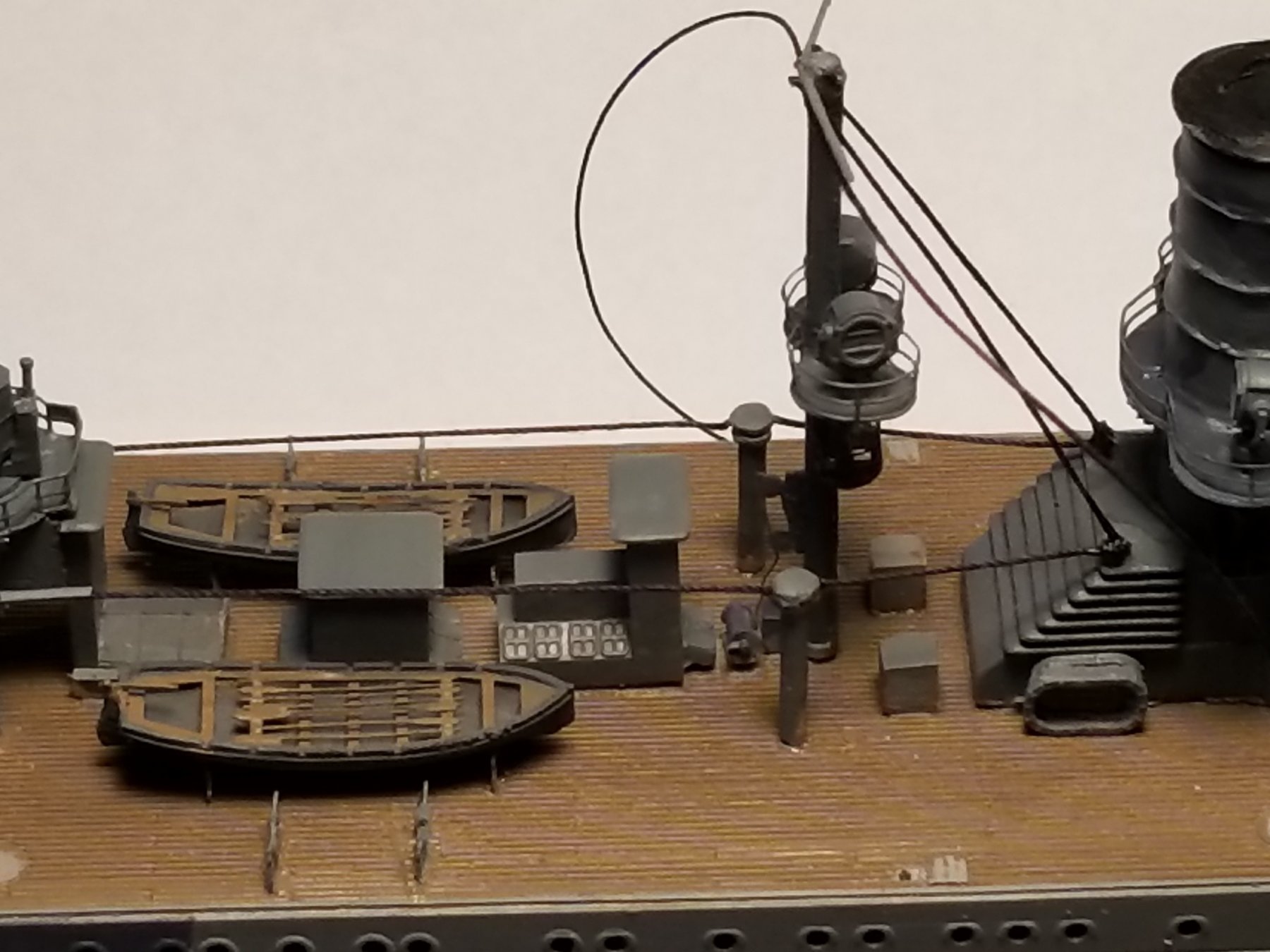
This post is for day 40, which brings us to January 23, 2018. In looking the model over I determined that the life rafts on the stern deck still have too much of the casting material to the undersides. I decided to remove them and shave off some more of the material. They fortunately popped right off without much damage to the deck. After I removed enough material I cemented them back on, looks much better. I also decided to cement the motor launches to the intended cradles. I may move these guns a few millimeters further aft, perhaps. In the previous post I mentioned the davits, so I figured why not cement them on. First I rigged the tackles and secured them to the davit posts to tie them out of the way of gun action. I used a few filaments of silk sewing thread for the rigging ropes. This and the next three pictures are copies I made from my 1:50 scale drawing of the davit arrangement. These are the kit davits I rigged with the supplied PE hardware. As mentioned, the ropes are just a few strands of silk from a very fine sewing thread. The davits cemented to the kit assigned places, which are accurate per my drawings. next to aft (right) davit you can see my scratch build eye bolt for the aft mast side stays and to the left is the boarding ladder. An overhead view. That round bare spot ir for the 15 cm gun. The motor launch is also cemented to its cradle. You would think that the aft mast side stays should be rigged aft of the mast center line. I did check up on this and found that Boris has it correct. Another overhead view looking aft. Cheers,


- 378 replies
-
- 9
-
-
- java
- pacific crossroads
- (and 2 more)
-
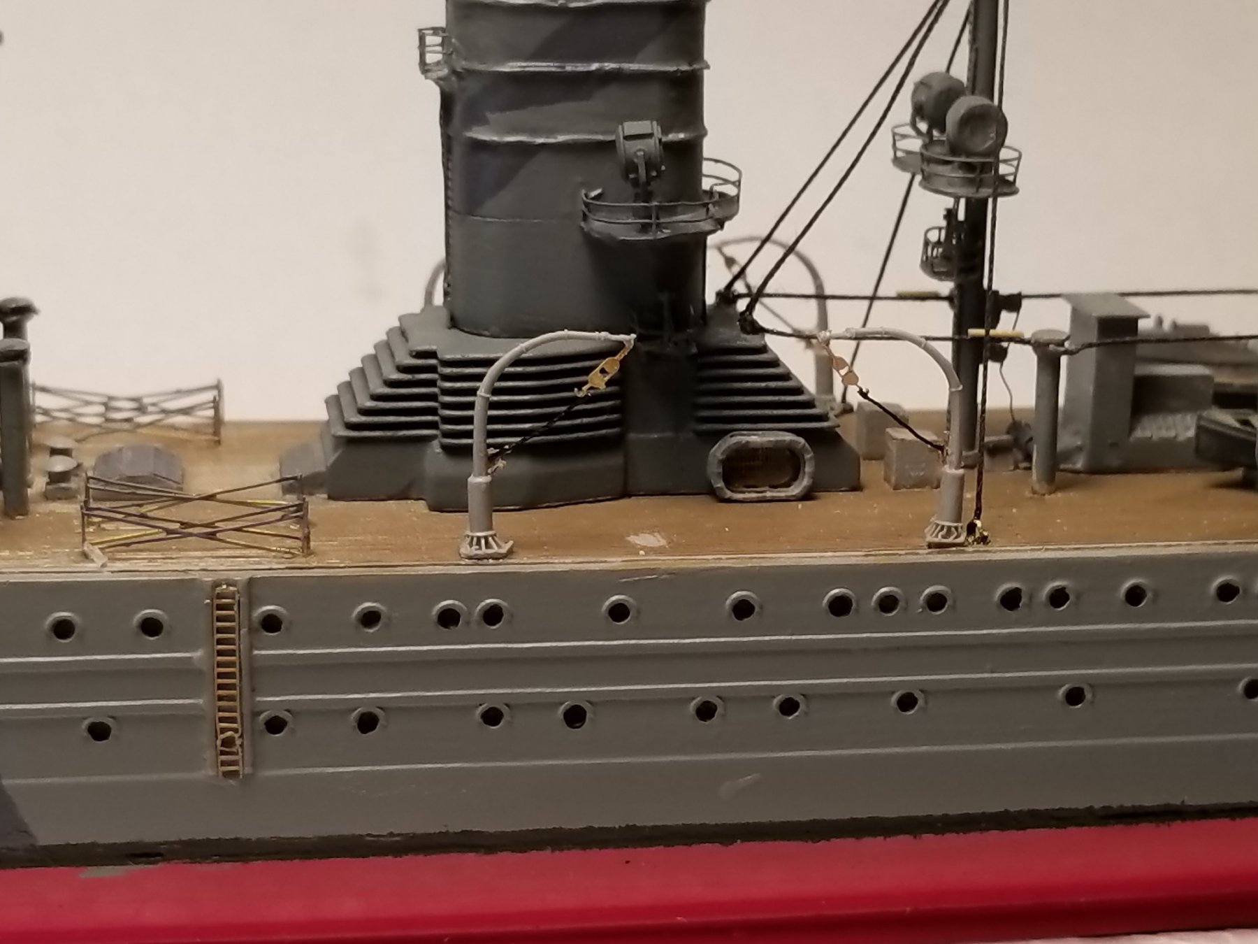
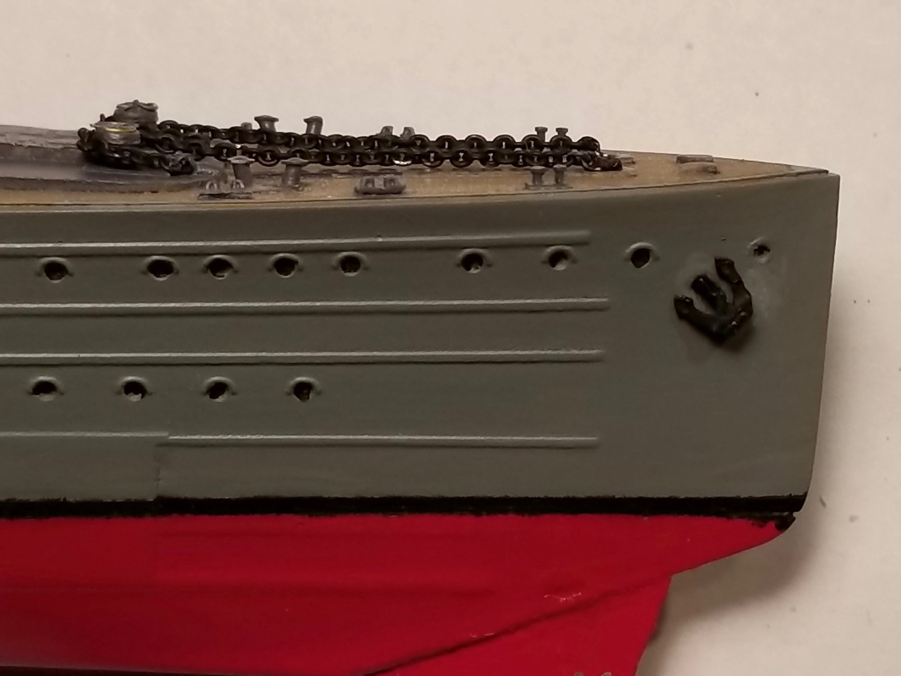
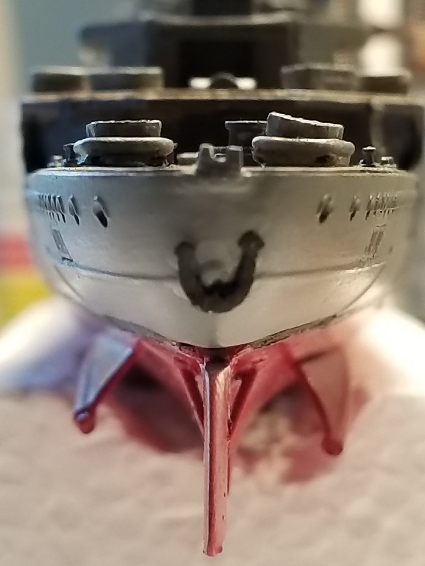
This post will be days 38 and 39, which brings us to January 18, 2018. A start was made with the standing rigging of the aft mast. I elected to use the thinnest polyester sowing thread for its non sagging properties. Scale wise it is still a little oversize but it does give the impression of some sturdiness. I needed to be extra cautious not to make it too taught or too loose. I didn't want to pull the mast out of plumb or with a sagging cable. The two forward stays were fastened to the top of the aft funnel vent housing first. I used the forward vent pipe cable fastening device - a tiny drop of CA - as the attaching point. As the CA was curing I carefully brought the thread to it with tweezers till they got a hold of it. This way I could slide the thread just enough to make it appear taught. When cured I simply cut thee excess off with the Exacto # 11 blade. For the side stay, which is fastened to a deck fixture, like an eye bold, with turnbuckle. I made en eye bold from brass wire, drilled holes into the deck and used the same thread. A little tricky in that the eye in the eye bold was a just enough to let the thread pass trough. Doubling back to the stay made it look too lumpy so I just put a dab of CA on it and cut the excess of. In the enlarged photos these "cables" do look like actual steel cables, which makes me a happy camper. Next I cemented the two ship's boats to their cradles but held off with the motor launches. I am not sure yet about it's involvement with the 15 cm gun next to it. With the guns in active firing positions would the hot powder gasses damage them? So I need to think about this a little before making a decision whether to mount them or not. If not, then what do I do with them? Hanging them in the davits is not an option because none of the photos I have with "Java" in action shows them there. I have the same thoughts about the gun between the two davits. Next I cemented the two support beams for the machine gun deck. These also serve as the supports for the seaplane crane gantries. This concludes the aft mast rigging. Day 39, 02/18/2018: Not much was done this day. I cemented all three anchors to their locations. Made and cemented the turnbuckles for the center vent pipes to their bracing cables and cemented the boarding ladders to the ship's side, where indicted. The forward stays are cemented on. The side stay wires are waiting. You can see my scratch build eye bold cemented to the deck just aft of the aft davit attach point at the edge of the deck. The side stay cemented to the eye bolt. The machine gun deck support posts are cemented in place. Just to the left on the hull you'll see the place for the PE boarding ladder. Bow anchor cemented in place. Stern anchor cemented in place. Looking at the 1:50 scale drawing it seems to be a little too large. I can either leave things alone or make a new anchor. The one shown in this photo is also a scratch build anchor. Close up vies of the seaplane deck with cradles and the forward vent pipe bracing cables attached to the forward funnel vent housing. That's the point I used for the aft mast forward stays. Bird's eye view of the aft mast deck. Here you can also see the dummy turnbuckles on the vent pipe bracing cables. Cheers,

.thumb.jpg.3159fa1a6b25e8b5eaeda5cc09c0745d.jpg)


.thumb.jpg.8d5aeff4c1b6c4e0af5f7bfbeefbda7f.jpg)

- 378 replies
-
- 8
-
-
- java
- pacific crossroads
- (and 2 more)
-
Nice work Kevin, again very believable. Cheers,
-
Congratulations Nenad, that's good news my friend. Cheers,
- 4,152 replies
-
- 5
-
-
- cutty sark
- tehnodidakta
- (and 1 more)
-
HMS ROYAL KATHERINE 1664 by Doris - 1/55 - CARD
Piet replied to DORIS's topic in - Build logs for subjects built 1501 - 1750
Very nice work Doris, it is a joy looking at it all. Those quarter galleries are a work of art and I'm sure you can pull it off. Cheers,- 1,035 replies
-
- 4
-
-
- royal katherine
- ship of the line
- (and 1 more)
-
Now that's an interesting concept, building a model of a sub with the interior. So far it looks rather sparse though. Is there more interior stuff to be installed? and why close it up? Cheers,

.jpg.6fa0f71c482a82a169566d13c0e8b56a.jpg)
.jpg.f1a940af4591948d4b7689b478028b10.jpg)

.jpg.cdf7b8447bbc98455a67dd7581ec5d2b.jpg)
_copy.jpg.4d2e783f69161f82f74e6f0a0e1d8de7.jpg)
.jpg.d5974fa778688b5197cce78e050e509d.jpg)


.jpg.6833861e47dc5632f709d24260c7c908.jpg)

.jpg.169e5d8fa366469af8cf7cd7eec2c1e6.jpg)
.jpg.982b3f0d868e8592a63514cb6c14396f.jpg)