MORE HANDBOOKS ARE ON THEIR WAY! We will let you know when they get here.
×


Keith_W
-
Posts
1,145 -
Joined
-
Last visited
Content Type
Profiles
Forums
Gallery
Events
Everything posted by Keith_W
-
 Thanks for the reply, Chris. I am somewhat confused as to why this 1:64 Prince should be "almost identical" in length to Amati's earlier 1:78 Prince?
 -
Saw your post in "latest full profile of your build" and decided that I HAD to see this. Wow, amazing ... at such a small scale! I take my hat off to you. Will be following from now on.
-
That HMS Prince has my mouth watering. Someone said to me when I was considering making a Victory (something I have wanted to do since I was a kid!) ... "every man and his dog is making a HMS Victory". Hence my Royal William. I would definitely buy a Prince. What scale is she going to be in?
-
I should hope so, Brian. Because my build order is different to everyone else's, I find that I am tackling parts of this build with no other build log (save Pete's I-I) to reference against. If there is one thing this site is good for, it is for seeking different opinions on how to tackle a particularly challenging aspect of a build. I could have kept all this info to myself and only show the outcome, but that's not the MSW spirit! If someone encounters a problem I want to see what they did about it!
-
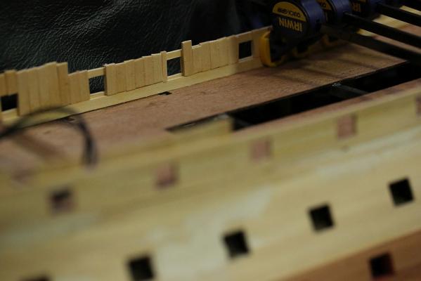
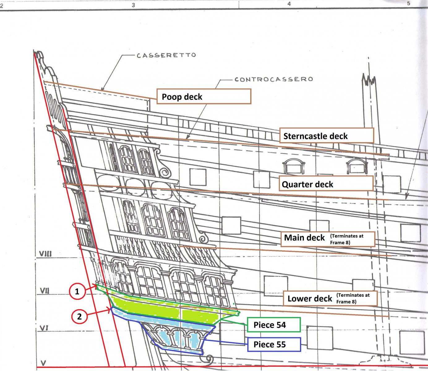
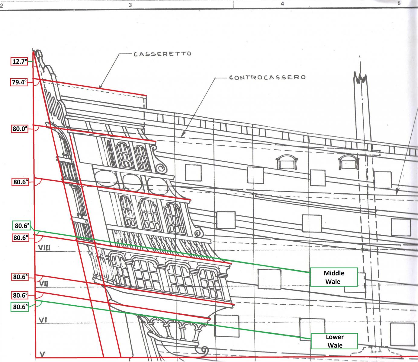
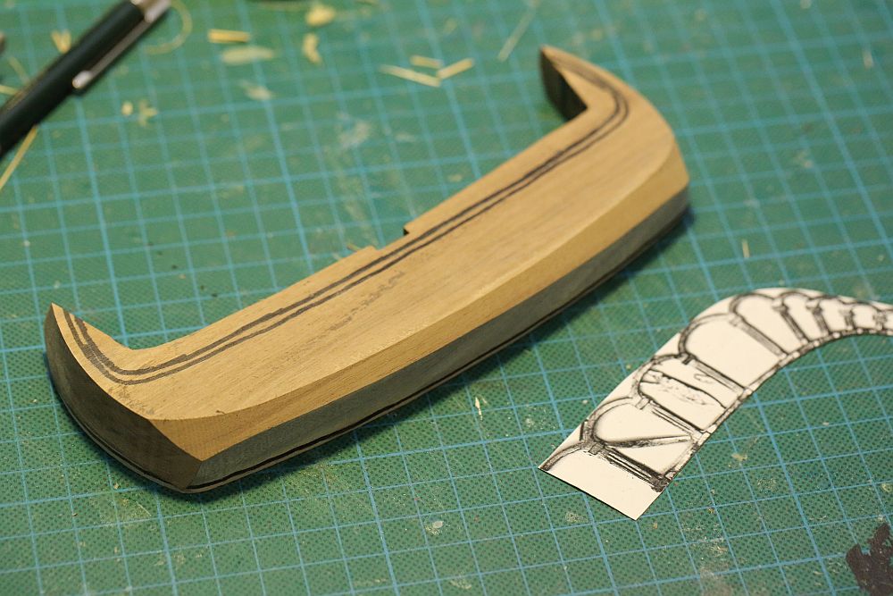
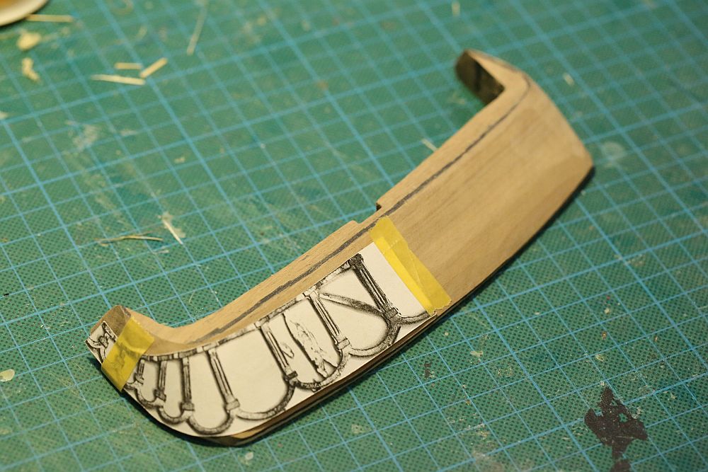
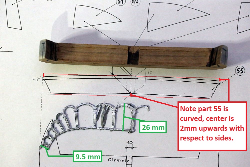
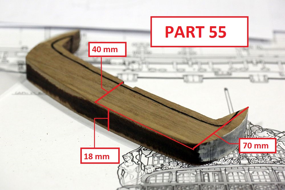
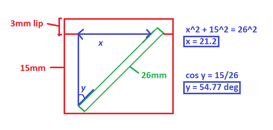
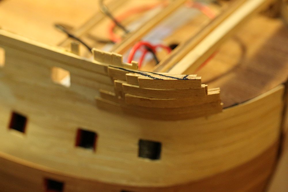
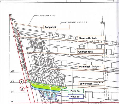
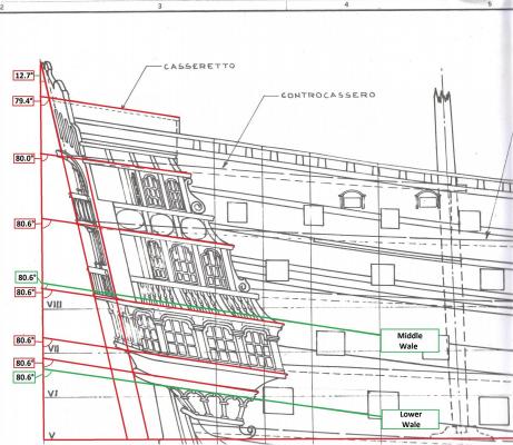
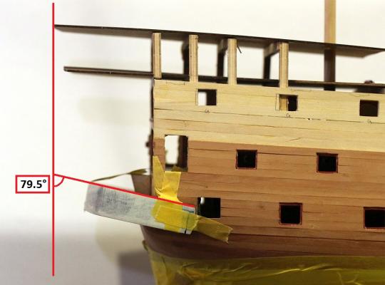
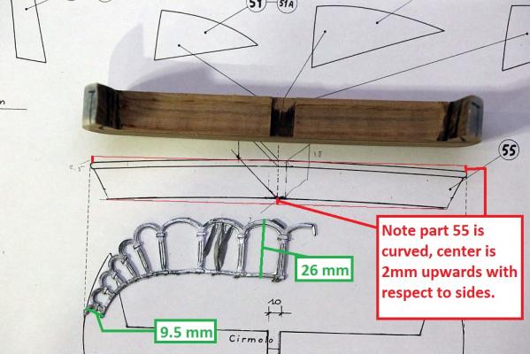
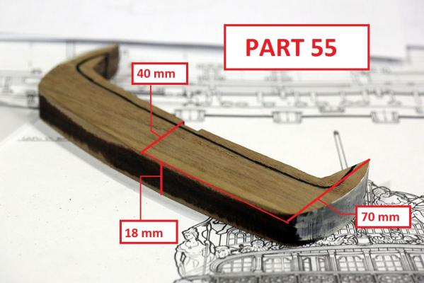
Thanks Pete, and thank you everyone else for the likes! As preparation for tackling the dreaded Part 54 and 55, I did a study of the various angles of the various features of the transom, to help shape and locate these parts: This study locates the rearmost lip of Parts. 54 and 55 with respect to the inclination of the transom. Note that (2) part 55 is exactly in line with with an imaginary line drawn down from the transom, whilst part 54 is projects outwards slightly. Also note that the angle of the lower deck is not the same as the angle of the transom! In fact, Part 54 (which starts significantly below the lower deck) ends up being 5mm below the lower deck at its rearmost projection. This study looks at the various angles of the decks, wales, and features. Note that Pete's interpretive-info admonishes the builder to incline the transom at the same angle as the wales. This advice is 100% correct. Note also the optical illusion that the higher decks seem to slope less than the lower decks. This was certainly the impression I got when I looked at the plans. Not so! The angle DOES change, but only by 1 degree! I then transferred all these angles to my model, with the aid of a square and a protractor. As you can see, the marking which I made was more or less spot on. I then proceeded to carve Part 54. I made a paper template of the arch decoration to help obtain the correct shape. Marks were made on the part to stop me from sanding beyond those boundaries. Other RW builders might feel a sense of dread after reading Julier's description of his difficulty with this part. But then, I have something that Julier doesn't have! (No, it's no talent). I have a Byrnes Disc Sander! All I needed to do was dial in the angles on the sander, then push the part in. Easy-peasy! Within 30 minutes, I had achieved this! Perfectly uniform and smooth. The metal arch template fit perfectly. To say I am delighted would be an understatement. I would kiss my Byrnes disc sander if I wasn't so afraid that it would sand my lips off. Having successfully shaped this part, I would like to share these observations with fellow RW builders: 1. The thickness of the part as supplied by Euromodel is absolutely correct - 18mm. Do not thin this piece any further. 2. The plan view of the part is also absolutely correct. DO NOT ALTER the plan view. 3. The lower outline of Part 55 can be obtained by aligning transom support piece 56 (supplied as laser cut mahogany ply) with the notch on Part 55. 4. The angle obtained by the above procedure, using a line drawn from the outer edge of Part 56 to the lower 3mm lip margin of Part 55, is 26° (when viewed from the rear), and about 70° (when viewed from the side) 5. Make sure you shape the piece internally before attempting to shape the piece externally. Next up in this gripping tale (maybe not) ...Part 54


-
Thanks, Geoff! Pete, I use resources from where I can find it. Your I-I has the largest wealth of detailed photographs of various aspects of the ship, as well as lots of notes about pitfalls to look out for and suggestions for builds. It is invaluable! However, as you can see from my build, I do take my own measurements, make my own decisions, and warn others of problems I have encountered. My build order is totally different to yours and Juliers, because I decided early on that the plans and the kit was not to be trusted and I would take reference off features which I had already built into the hull, rather than trust the plans fully.
-
Interesting, I would have thought that the double hull should be quieter because it prevents noises from inside coming out, similar to double glazing in windows? Oh well, learn something new!
-
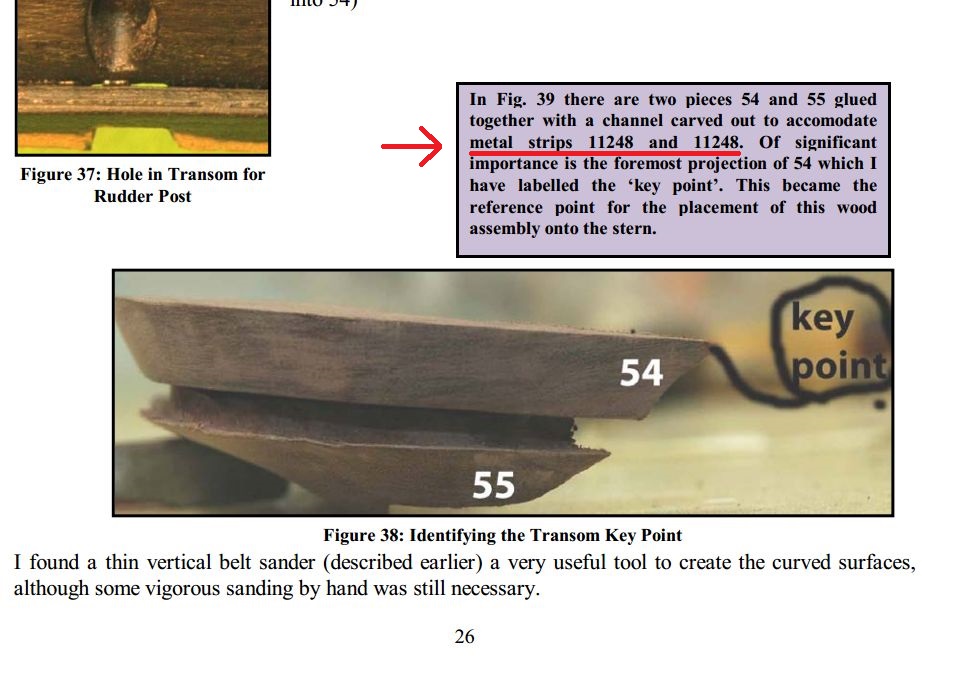
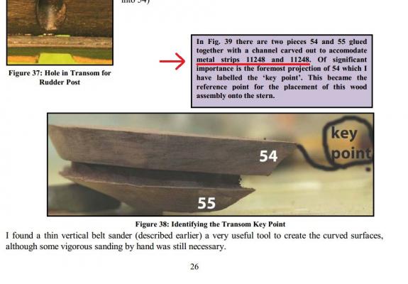
Ahh, I see. I must have missed the part in the instructions where they indicated that a substitution had been made. You see, p.26 of the Royal William Interpretive Info says this: I guess I could be forgiven for hunting for those strips in the metal part bags
-
I have to agree. When I ordered my kit, the replies were prompt and courteous. When I ordered some extra guns, I again got the same service. It does appear that these parts - 11247, 248, and 249 are missing from Denis' kit and mine. Sadly, I only realized it after my guns were shipped. I do not wish to trouble Massimo again, so I did not order these parts. I have a plan to scratch build them.
-
I missed the start of your build log, but i'm pulling up a seat for this one. Thanks for the lesson about Russian subs. I think they certainly look much cooler than American subs Keep the updates coming.
-
Float a Boat, in Ringwood. I have selection of drill bits down to 0.2mm (!!!): http://www.floataboat.com.au/ If you want a 1mm drill bit, you can find it in Masters or Bunnings. I stock about 10 of these at any one time in case of breakages.
-
Many years ago I tried Collectorz to help archive my massive CD collection. It didn't work so well. To find your CD, you could either insert it into your CD-ROM drive (and the PC would search the database), or you could scan the barcode, or you could do a search for the CD title. The software would then create an entry for you. I was not pleased when it split the composer J. S. Bach into ten different composers and simply archived the discs everywhere under names like BACH JS, BACH Johann S, JS Bach, J. S. Bach, Johann Seb. Bach, Johann Sebastian Bach, etc. I would have to manually edit each title to get the thing to archive properly. I ended up having to edit EVERY entry. When you have a CD collection that is somewhere close to 2000 discs, this gets very tiresome very quickly. I gave up after I got through 200 discs. Does the Android app have the ability to use your phone camera to scan the barcode?
-
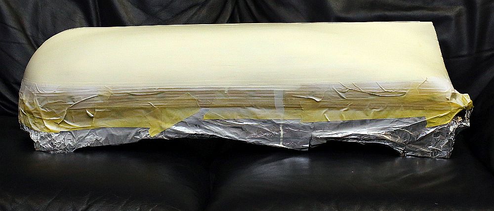
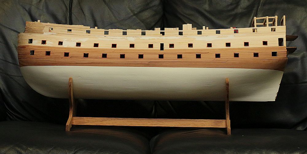
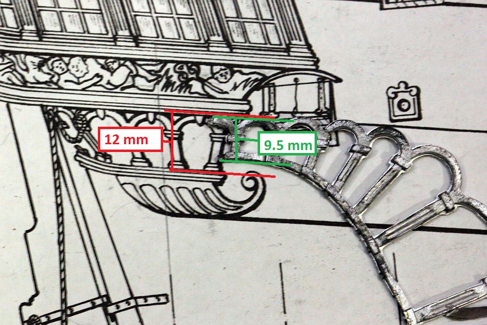
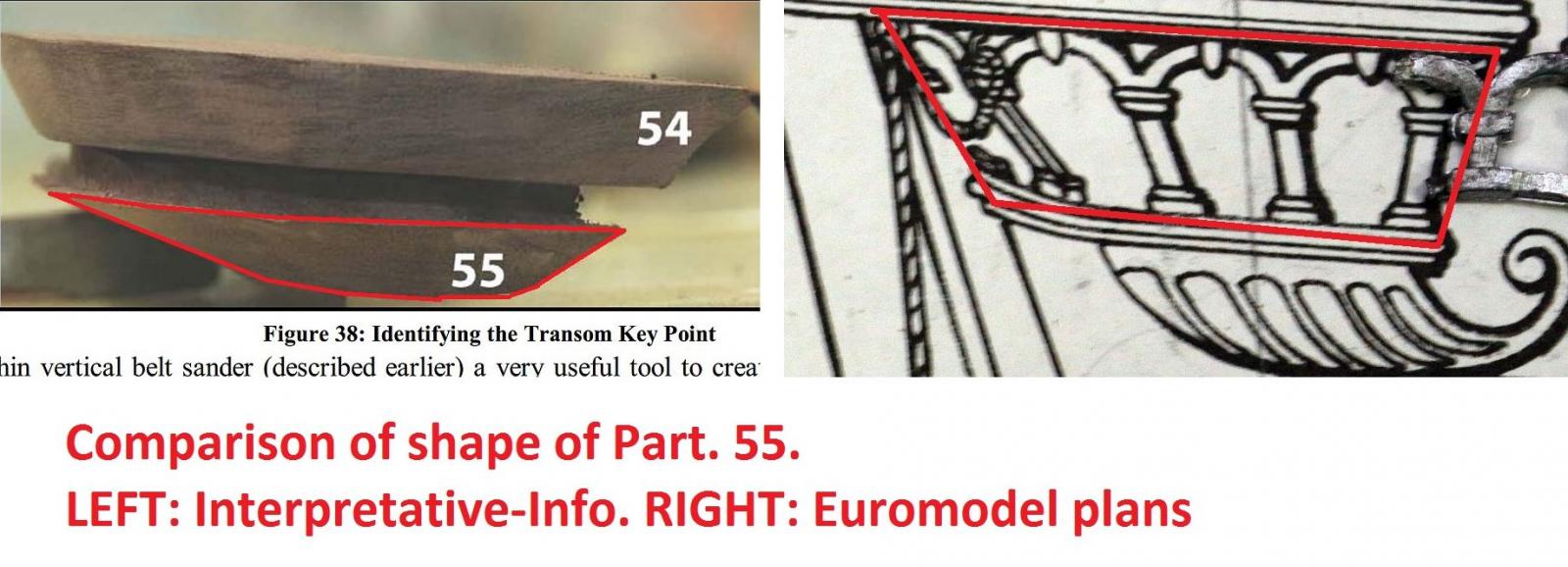
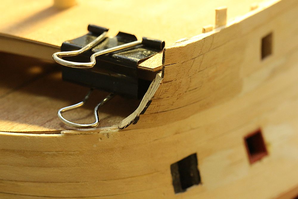
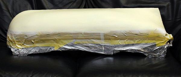
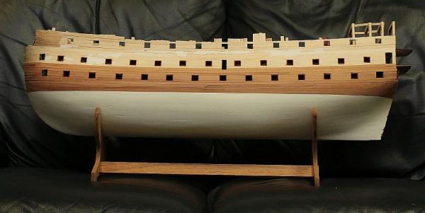
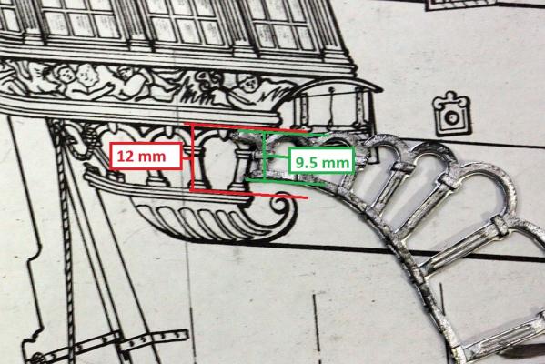
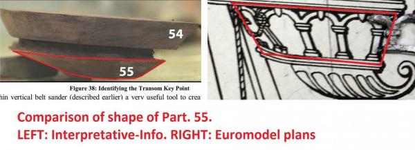
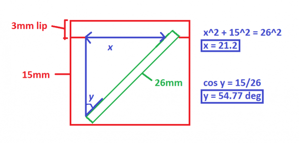
Thanks for the likes, everyone. I have a little update. Some of the stuff I talk about might be really boring for those of you not building this ship, but i'm putting it out there for the benefit of other RW builders. I drew the waterline, then masked it off and painted the bottom white. I first applied 3 coats of Tamiya's white primer, sanding down each layer with 400 grit sandpaper. I then applied four dilute coats of Vallejo "Ivory White", again sanding down each coat. It is now really smooth! I just LOVE removing masking tape, it's better than opening Christmas presents! I was rewarded by a clean paint line. If I DIDN'T get a clean paint line, I would have had to sand it down and paint again. I allowed 48 hours for the paint to cure, then wrapped the whole thing up in masking tape again to protect the white finish while I work on the rest of the boat. I then moved on to tackle the transom support. This involves carving two pre-shaped pieces down to the correct size. Keith Julier calls this the most challenging area of the build. Piratepete's "interpretative info" devotes 8 pages to discussing this subject. Indeed, the shaping of the rear transom support is not easy and is NOT helped by the plans giving a completely misleading suggestion of the profiles of pieces no. 54 and 55. The true shape of the lower support piece Part. 55 is hinted at by looking at Plan Sheet No.8, but even that does not reveal its exact shape because it is shown hidden under metal decorations (more to say about the accuracy of these plans in a moment). Indeed, if you take a look at the diagram above, it would appear that the suggested taper on Part. 55 is fairly gentle. NOT SO! Take a look at PiratePete's I-I. Observe the severe taper on the lower piece: It is as I suspected. There is no way to correctly determine the shape of this transom piece prior to shaping it. This SHOULD cause considerable anxiety, because the metal decorations have to fit in the space above it. Get the shape and thickness of this wrong, and you will either overcrowd your metal pieces, or have empty spaces in between! The only way to correctly determine the shape would be to test fit the metal arch decorations which should be attached to Part. 55. So I got them out of the bag. Uh-oh. The plans (which are supposed to be a 1:1 reproduction of the ship) indicates that the height of the arch should be 12mm. But the metal pieces supplied by Euromodel are 9.5mm. Right, so I can't trust that the metal pieces supplied will actually correspond with the plans, then! Talk about flying blind! * And yes I am aware that both Julier and Pete say that the plans indicate a scratch built model. However, it would have saved considerable anxiety if Euromodel had produced parts that actually fit the plans or vice-versa in the first place. I decided to work out the correct dimensions needed by using some maths. Above is the transom support piece which has been shaved internally so that it fits the model. I have supplied dimensions of the piece as supplied by Euromodel. You can also see that I have painted the side white to help make it easier to see any markings I need to make on the piece. The last time I touched Pythagorean theorem and trigonometry was in high school, more than 20 years ago ... so I was a little nervous about doing these calculations. It looks as if the width of the piece (40mm as supplied by Euromodel), should be reduced to (21mm + allowance for curvature of the metal arch + allowance for support piece 56). I will bring it down to 30mm as a start, then check everything for fit. I do have a question. Pete indicates in his I-I that metal railings (Part 11247) can be fit in a channel carved into Part 55. I have no such metal railings in my collection of parts. Is this something that has been deleted? Brian? VinceP? Denis?

-
Hello Max, congratulations on finishing your build. She is truly beautiful and you will enjoy her having pride of place in your living room.
- 153 replies
-
- 2
-

-
- royal caroline
- panart
- (and 1 more)
-
Hi Daryl, next meeting is at 7:30pm on Wednesday 4th Feb. Details here: http://shipmodelsvic.org.au/index.php?page=meetings Hope to see you there.
-
Proxxon compound table -- Opinions?
Keith_W replied to rtropp's topic in Modeling tools and Workshop Equipment
If you are talking about this: http://www.proxxon.com/en/micromot/27100.php ... then I would say I have mixed feelings about it. I'll just say that this compound table is the major reason I am thinking of selling my MF70 mill and upgrading to a Sherline. The chief complaint is the amount of backlash on this table, mine has about 0.5mm of backlash. Also, the table has a habit of rocking disconcertingly when you turn the handles. Both of these can be worked around, but I am not happy with it. -
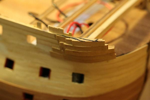
Thanks Greg! The extra wood is there to allow me space to trim it back once I test fit the beakhead rails. I have not done that yet.
-
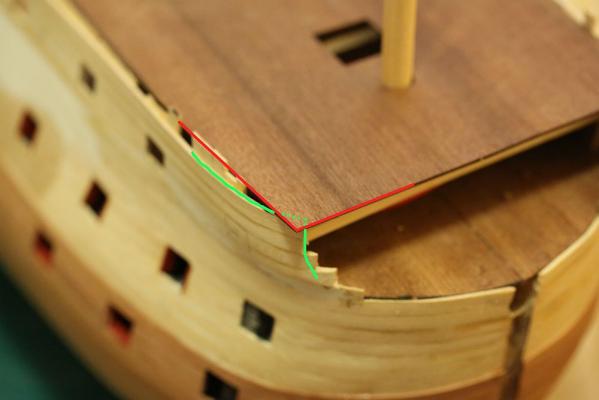
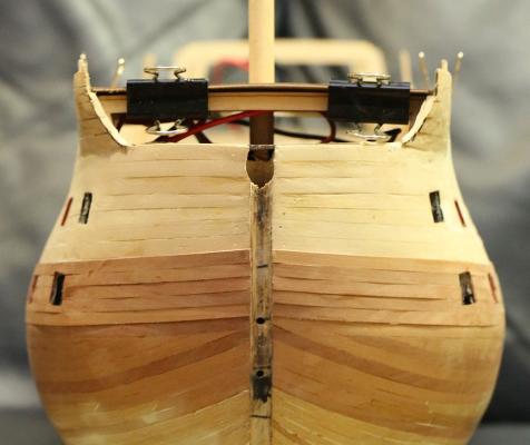
Arghhhhhhhh I made a major blunder! When I test fit the fo'c'sle, I saw that the deck ends well ahead of bulkhead F. Given that bulkhead F is tapered with respect to bulkhead E, you would THINK that the planks ahead should be curved. So I indeed curved my planks ahead of bulkhead F, following the line of the main deck. As you can see from my diagram, the green line I have added shows my planks curving underneath where the deck is supposed to end. A quick check of the plans confirmed that I had indeed made a serious error. Now I faced a choice of terminating the deck early, or trying to bulk up the bow planking to accommodate the fo'c'sle deck. I chose to do the latter. Which meant that I faced an additional problem of how to fair the planks in without distorting the shape of the bow too much. I pored over pictures of the completed ship, which at least assured me that mistakes here would be covered by the beakhead rails. I also studied closely other build logs on MSW for help. So far nobody has mentioned this issue. Oh well. I started bulking up the planks by laying strips of second planking material. Once done, I trimmed it back. I think it looks OK!

-
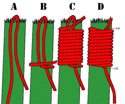
You're welcome, Michael! I found it by doing a google search. Here are more knots for you. http://www.animatedknots.com/commonwhipping/
-
This is how.
-
Very nice! How did you cut out the letters?
-
Medic, I prefer to use PVA glue when possible. But when I have to negotiate tight bends, I prefer using thick CA with spray on accelerant. The thick CA prevents the glue from running all over the place - it's more gel than liquid. Apply sparingly, attach your planks, then use the accelerant. The reason I don't use this 100% is because CA joints are brittle and not as strong as PVA joints. And it's more expensive.
-
Looking good, Medic. Great job if it's your first build! Probably no need to steam bend the second layer of planking unless the bend is very severe, e.g. there are some sharp angles at the stern of your ship. Maybe 3-4 planks a most. You will need to taper the planks as you did with your first layer, though. Incidentally, are you an MD? I'm an oncologist.
-
I can't take my eyes off those sweet lines of hers. I just want to caress and touch. Good thing she's a ship model and not a person, otherwise I would get a slap on the face for admiring so much! You're doing a great job, Jim. Please keep the updates coming.
-
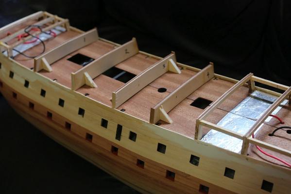
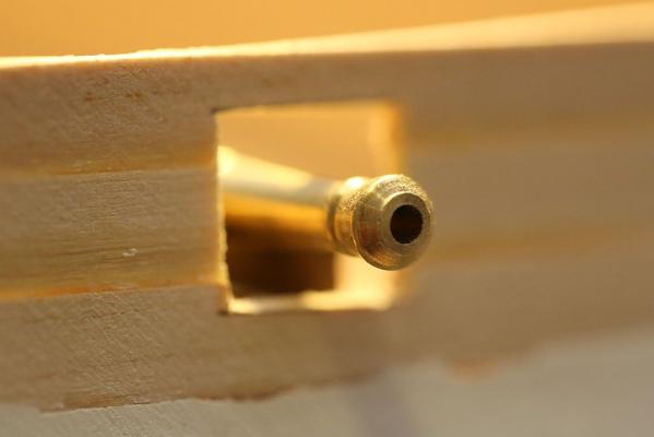
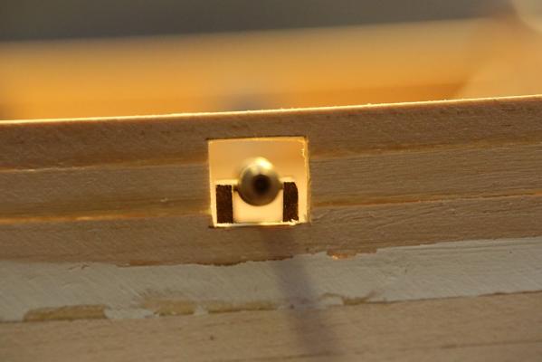
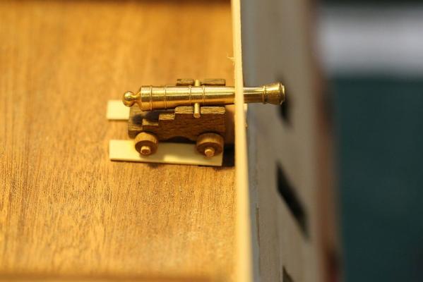
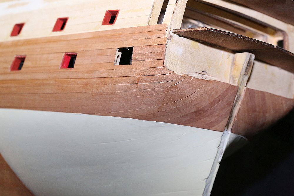
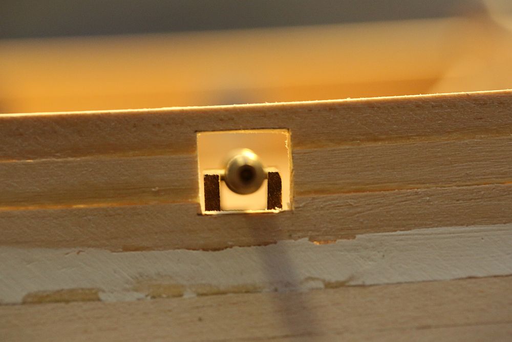
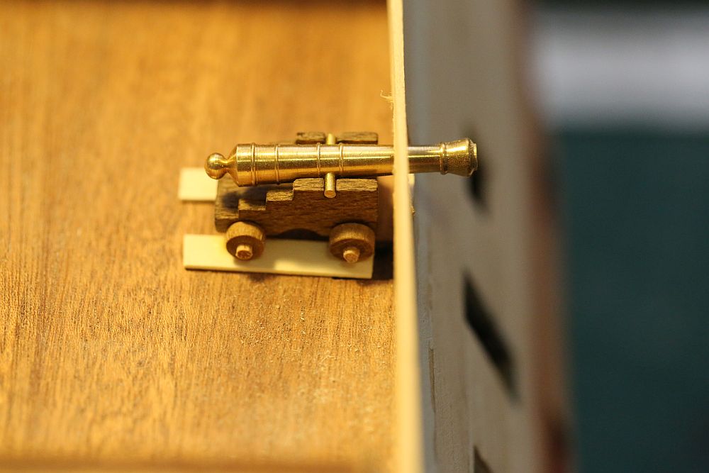
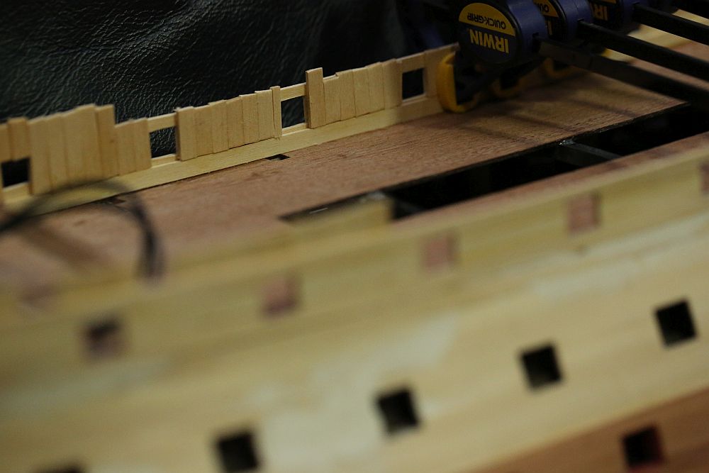
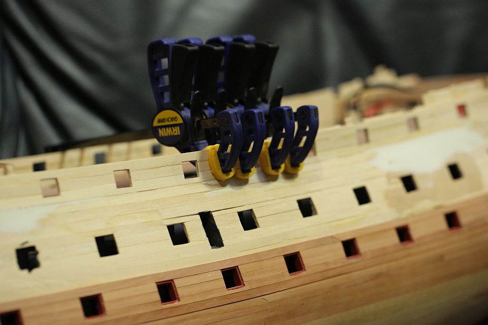
I have a couple of weeks off work! This is my reward for working like a dog over Christmas so that others could have time off. So what do I do on my days off? Why, I spend 12 hours a day working on my ship model! This is hard, going back to work will seem like a holiday. Anyway, here is some progress. I was not happy with the planks above the main deck level. As mentioned earlier, these are unsupported. On my first attempt, I copied VinceP's method of slowly gluing the planks with CA. It turned out OK, but after sanding the planks they became thin. After inverting the ship a few times to work on the second planking, the inevitable happened and they became warped. I was determined not to make the same mistake twice. I fabricated some temporary bulkheads and started again. Now that I have something to clamp the planks to, I was able to use my preferred cement - PVA. After the glue had dried, I proceeded to cut out the gunports. I wanted to do this as quickly as possible so that I can install a double thickness of first planking material to stop it from warping again. To locate the gunport, I threw together a kit cannon, along with some planks I will be using for the deck to gauge the correct height. A pin was pushed through the planking, and the height checked against the gun barrel. Once I was happy with the location, I mounted my square template on the pin (see earlier posts) and drew out a square. A steel ruler and a scalpel ensures neat cuts. The hole cut out, the cannon is mounted again to check if the position is satisfactory. As you can see, it is perfectly OK! Once the gunports were cut out, I started to install the layer of first planking. As you can see, I am installing it perpendicular to the first run of planks. Hopefully this will give it extra strength. I clamped down each run of planks to ensure the fit is tight. You can also see that I have extended the planks at the fo'c'sle to support the extra planks that will be installed there. Oh yes, you can also see in the last picture - I have now extended second planking to above the level of the lower deck gunports. I decided to paint over the gunports with red ochre, and it is a much more pleasant shade of red than the rather lipstick-like Vallejo flat red.