


KeithAug
-
Posts
3,867 -
Joined
-
Last visited
Content Type
Profiles
Forums
Gallery
Events
Posts posted by KeithAug
-
-
Hello Barbara, a very touching and inspirational introduction, your father is a very lucky man to have you as his daughter.
- geoff, druxey, Barbara Lange and 2 others
-
 5
5
-
-
-
Beauty in miniature, very well done.
- popeye the sailor, Piet, mtaylor and 1 other
-
4
-
Nice work Kees. The rudder is very impressive.
-
On 09/04/2018 at 8:27 PM, KeithAug said:
I am also going to add a moveable end stop
20 hours ago, mtaylor said:we guys have a reason for saving "stuff" that the Admiral thinks should be binned
Mark - given your comment you may find the moveable end stop interesting.
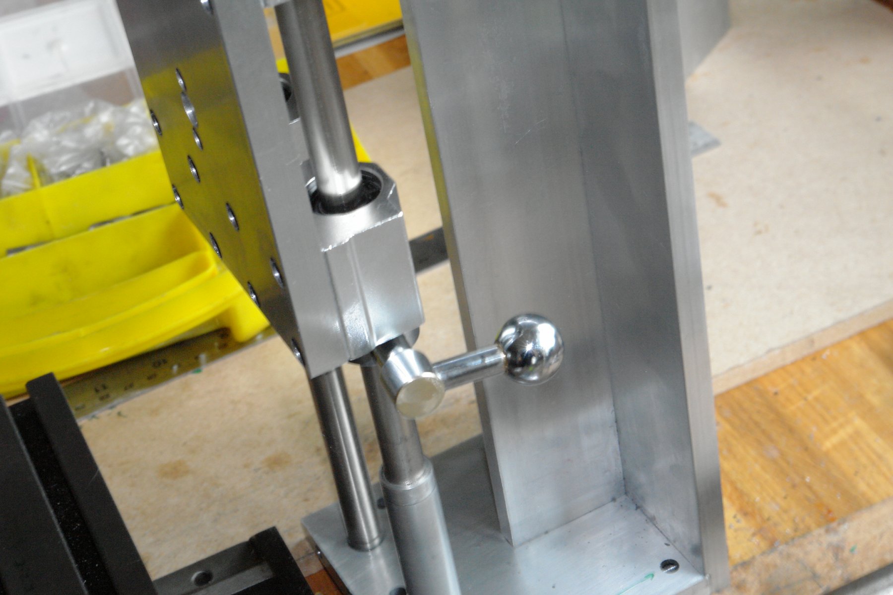
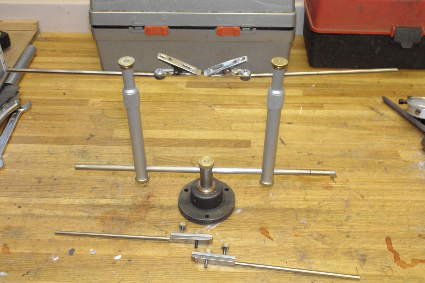
A couple of months ago I refurbished the daughters bathroom and amongst other things recovered the following:-
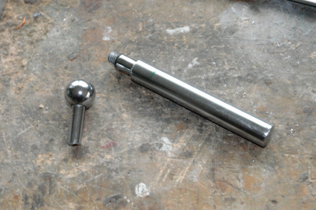
The bar is the handle from a mixer tap and the ball with shaft is the end of a wall mounted toilet roll holder.
I made a clamping ring from 1" bar - bored to have a close fit on the runners and drilled and tapped to take the end of the mixer tap handle (M8).
The ball shaft was threaded and the handle was bored and tapped to take it. The end of the handle was removed and returned to the rainy day bin.

Recycling can be very satisfying.
- aviaamator, Canute, druxey and 4 others
-
7
-
-
Hi Nils. The spar tapering technique is interesting - bit like the technique of a two gun gunslinger from a 1950's western.
- mtaylor, Piet, popeye the sailor and 3 others
-
6
-
On 07/04/2018 at 10:02 PM, aviaamator said:
I'm using The Altivar 312 speed controller
Thank you I'll bear it in mind as an option.
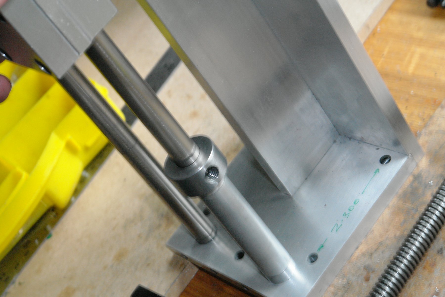
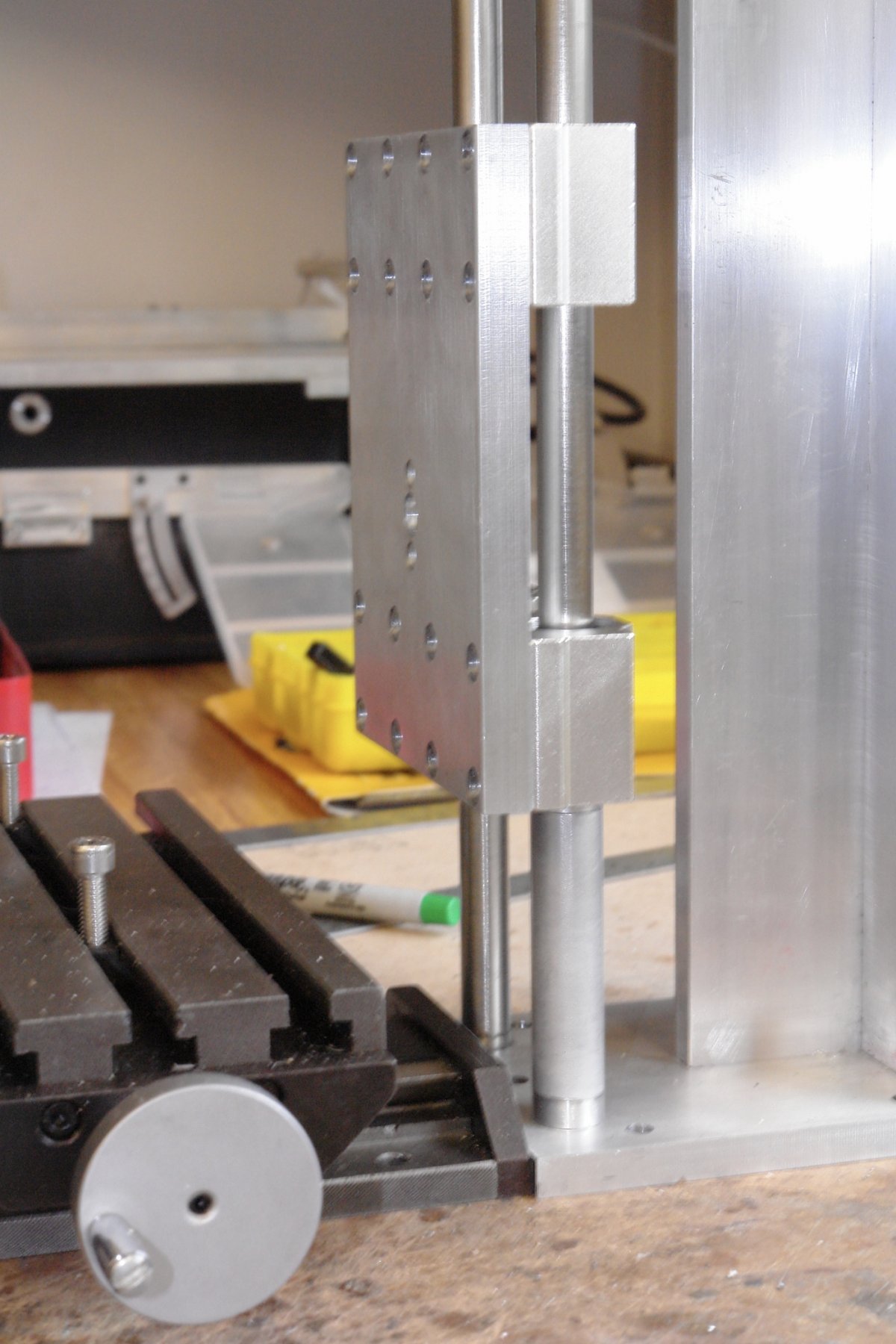
A bit more progress:-
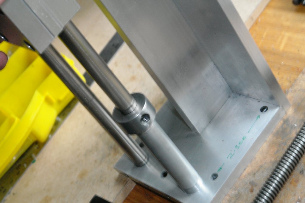
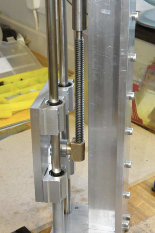
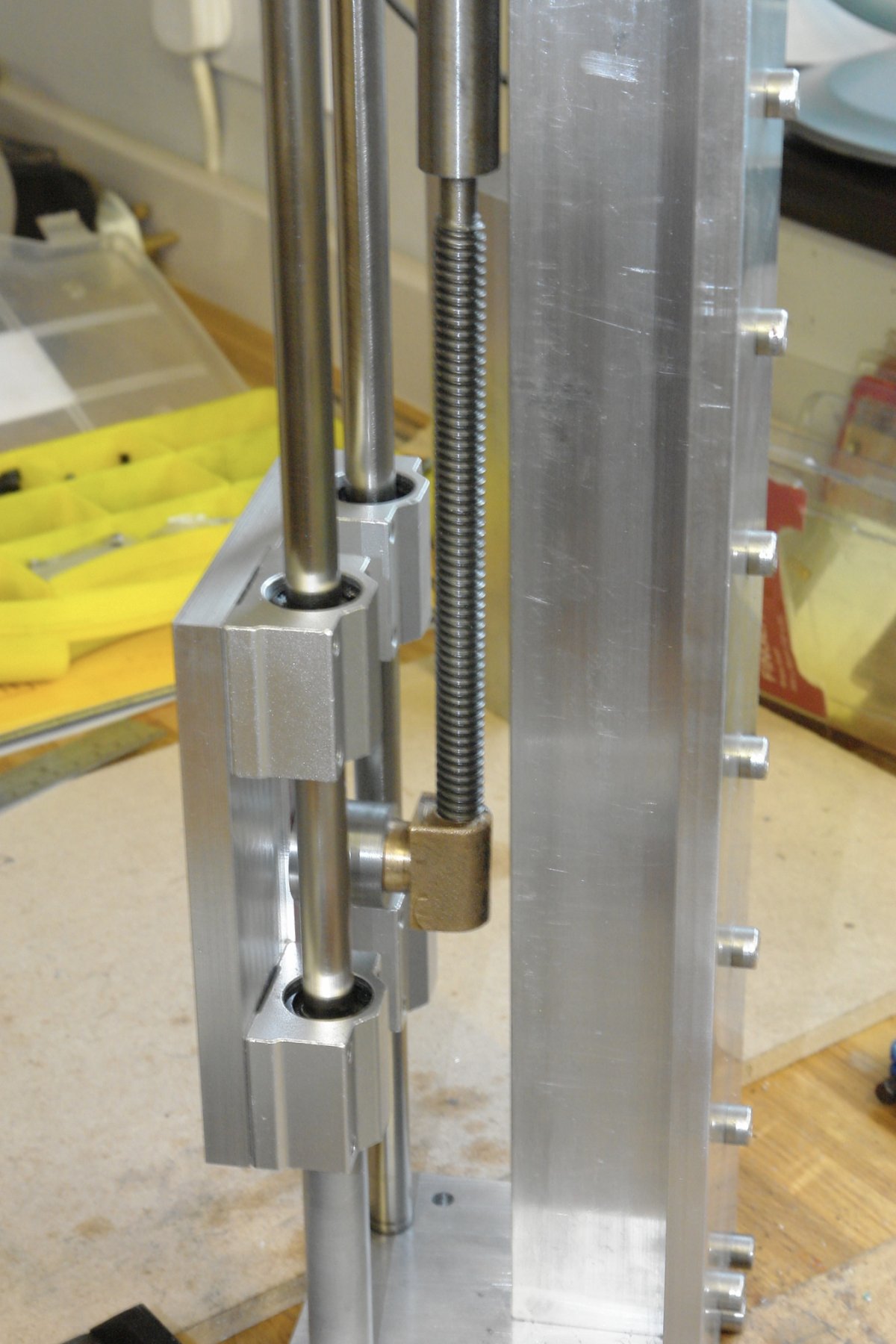
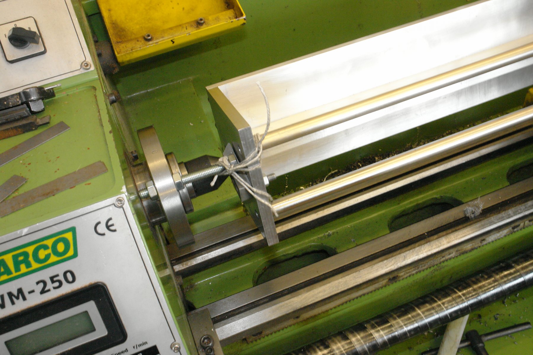
I needed a stop to limit the lower position of the bearing plate. Without a stop the plate would fall off the end of the vertical leadscrew. I used an aluminium tube (from a broken tripod) with end collars machined accurately to fit over one of the running bars. I am also going to add a moveable end stop to the bar to allow me to preset repeatable depths of cut.

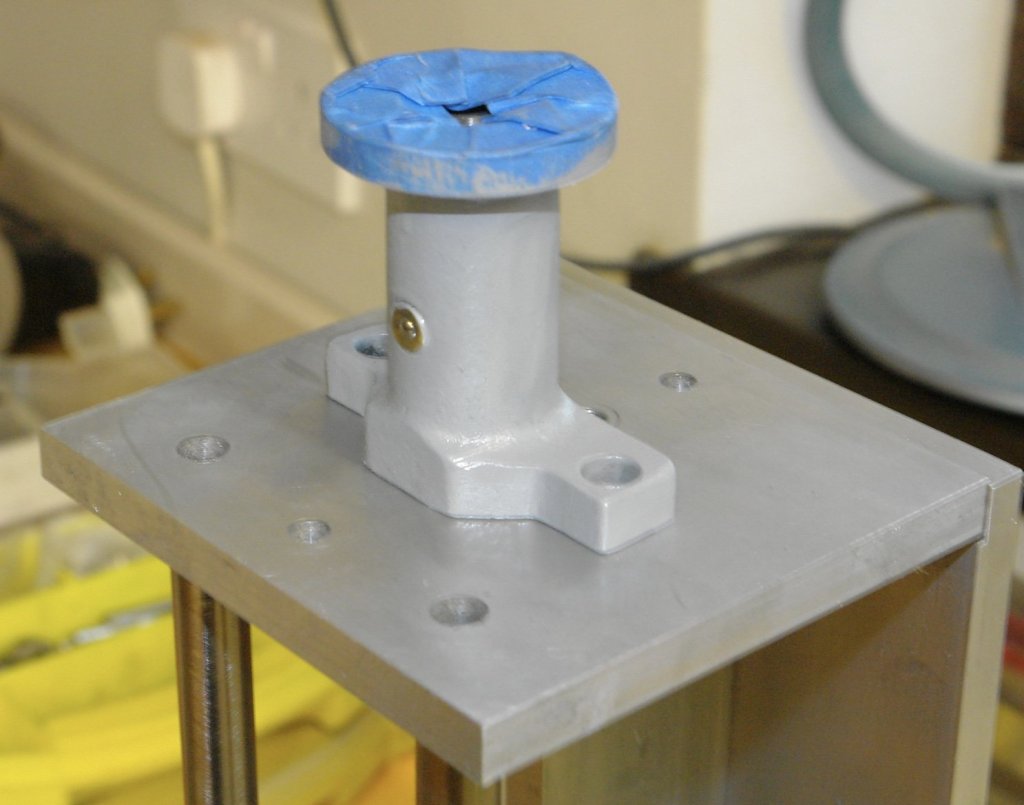
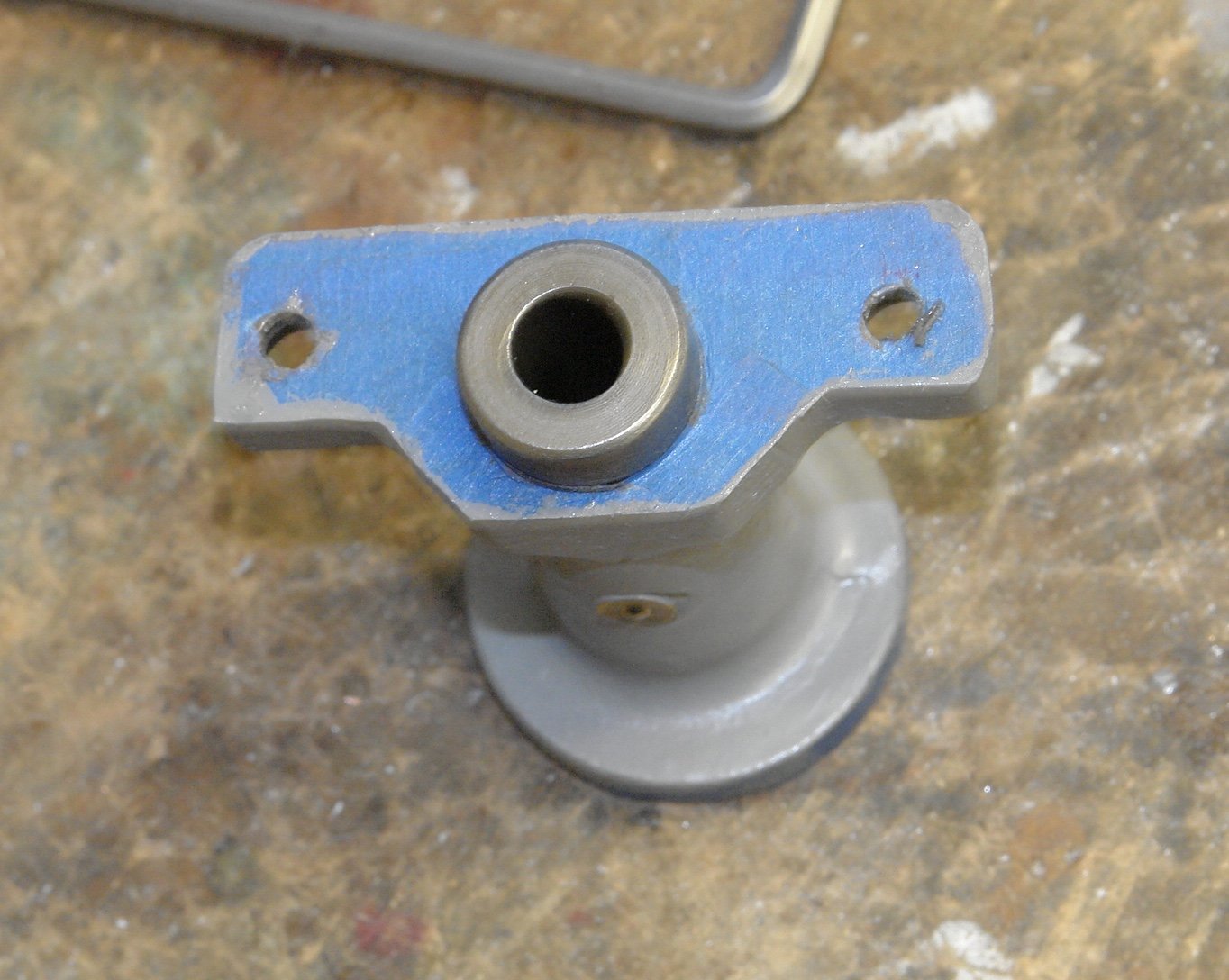
I decided to tidy the lead screw bearing casting, the paintwork was a bit battered so I removed it with the grinder wire wheel.

The casting was masked up and given a couple of coats of primer.
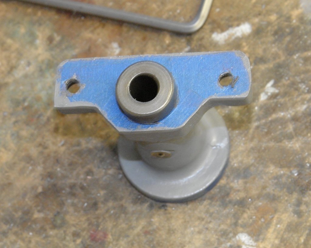
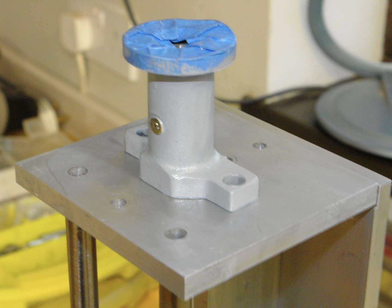
I needed to mount the casting on the top plate. This involved establishing the relative positions of the 3 holes (central large hole and 2 smaller holes). By various (not too precise) means I measured the pitch of the smaller holes as 1.994". The large hole is not on the same axis as the smaller holes and measurement, addition and subtraction give me a displacement of .194". Not withstanding the measurement I reasoned the original designer wouldn't have chosen such obscure measurement and guessed that the actual measurements were 2" and 0.2". So this is what I used for machining the mating top plate. The smaller holes were drilled and tapped and the central hole was bored accurately to 0.750" to take the boss on the casting.
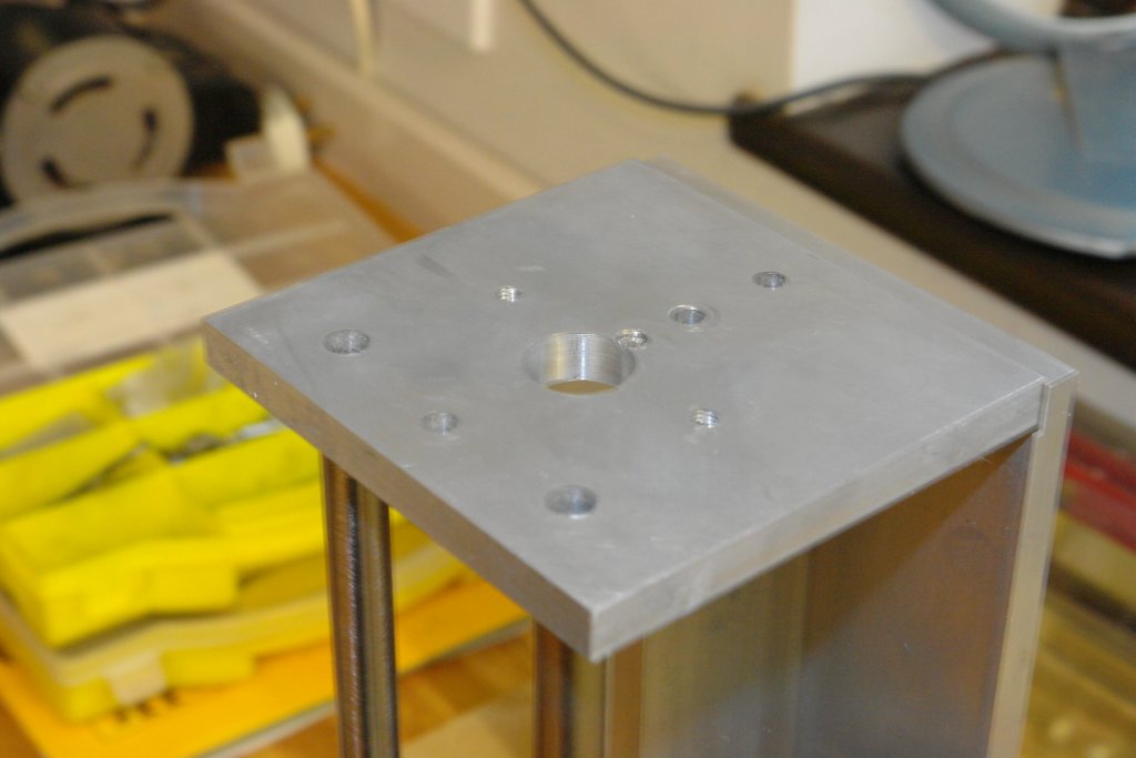
Fortunately everything lined up.
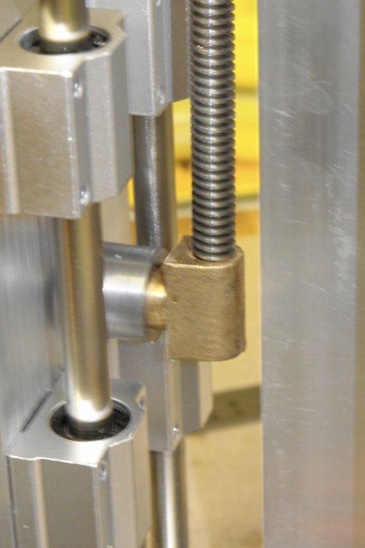
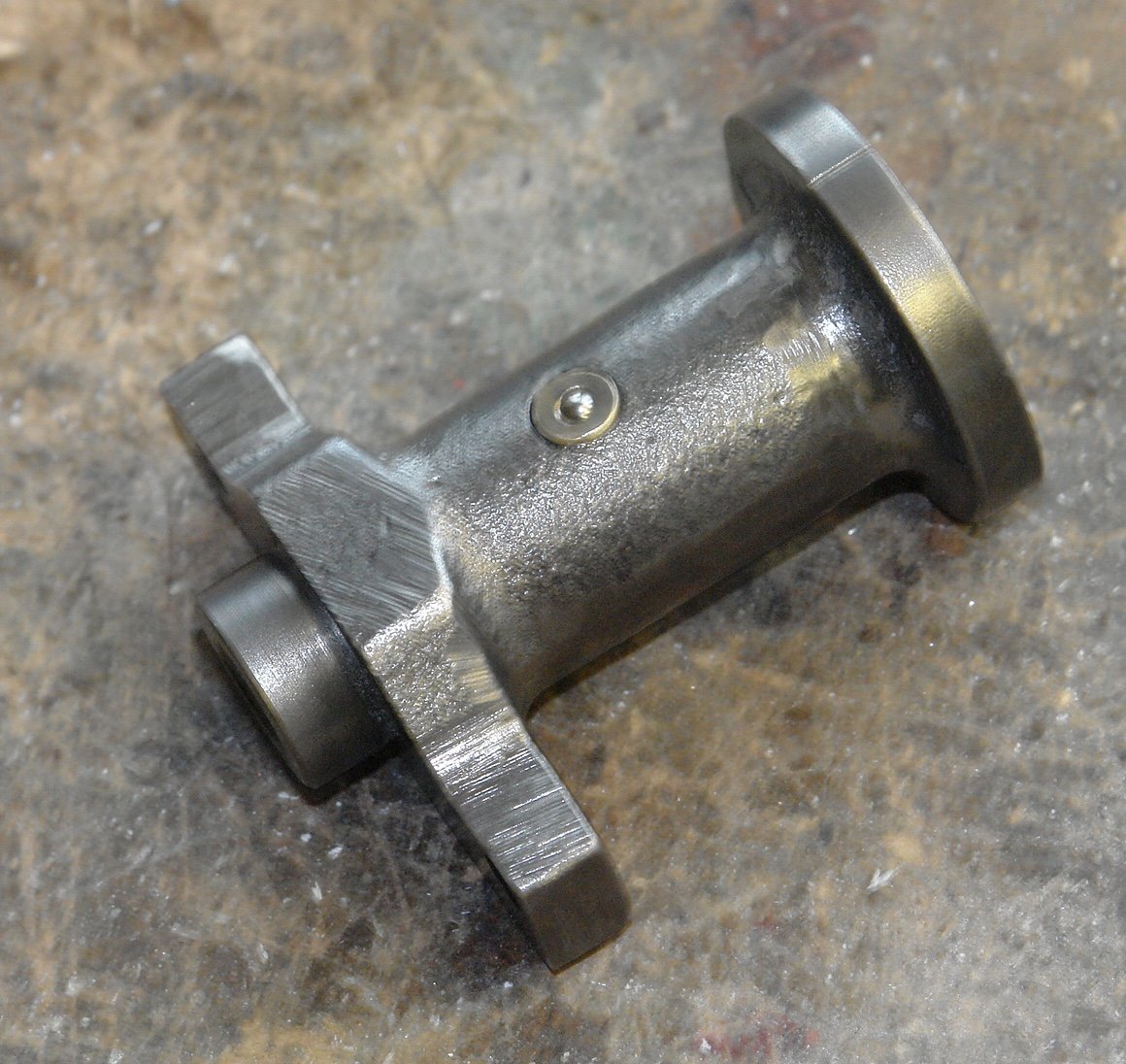
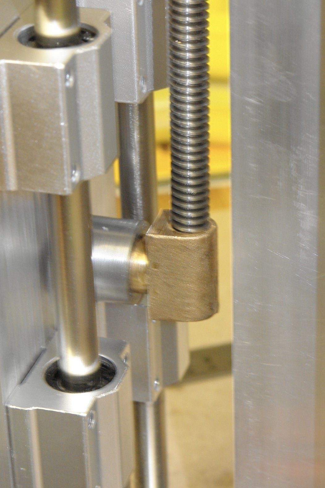
I also made the boss for the back of the bearing plate. This is required to mount the leadscrew nut.
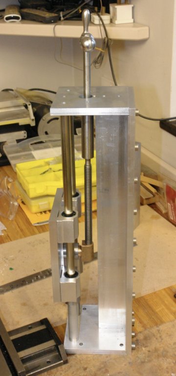
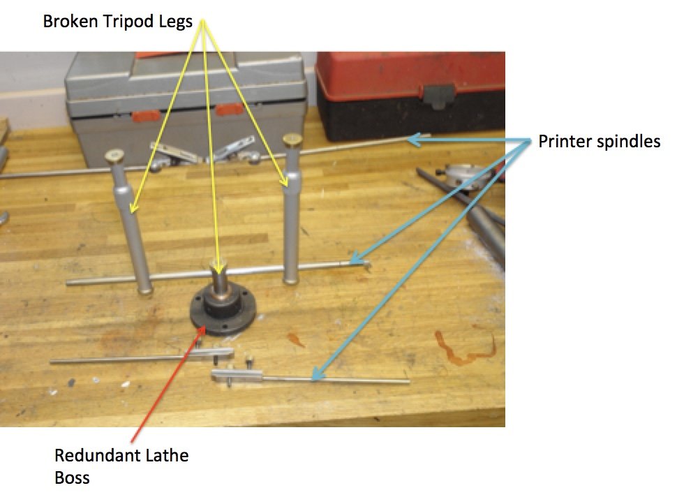
On a different subject and in parallel I decided my scrap bin had enough parts for me to join the Michael Mott 3rd hand club.
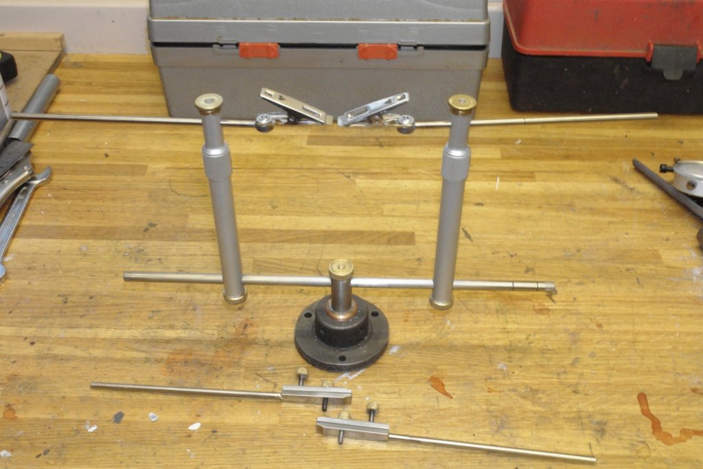
The origins of the parts are:-
- Canute, paulsutcliffe, aviaamator and 4 others
-
7
-
Brilliant work Dan. Funnels look amazing.
- mtaylor, hexnut, paulsutcliffe and 3 others
-
6
-
-
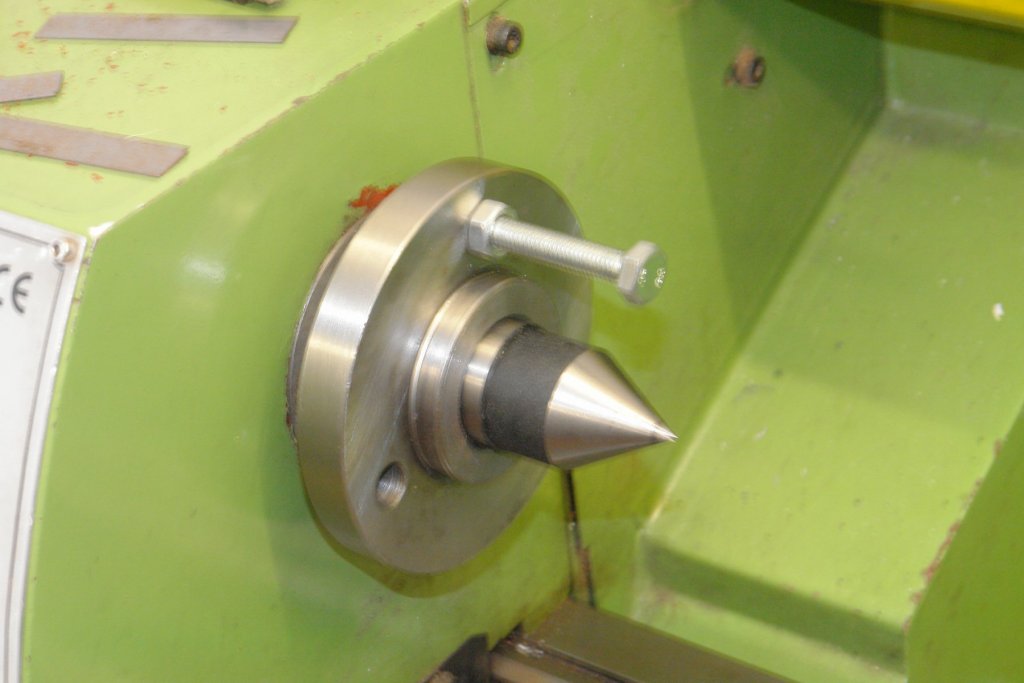
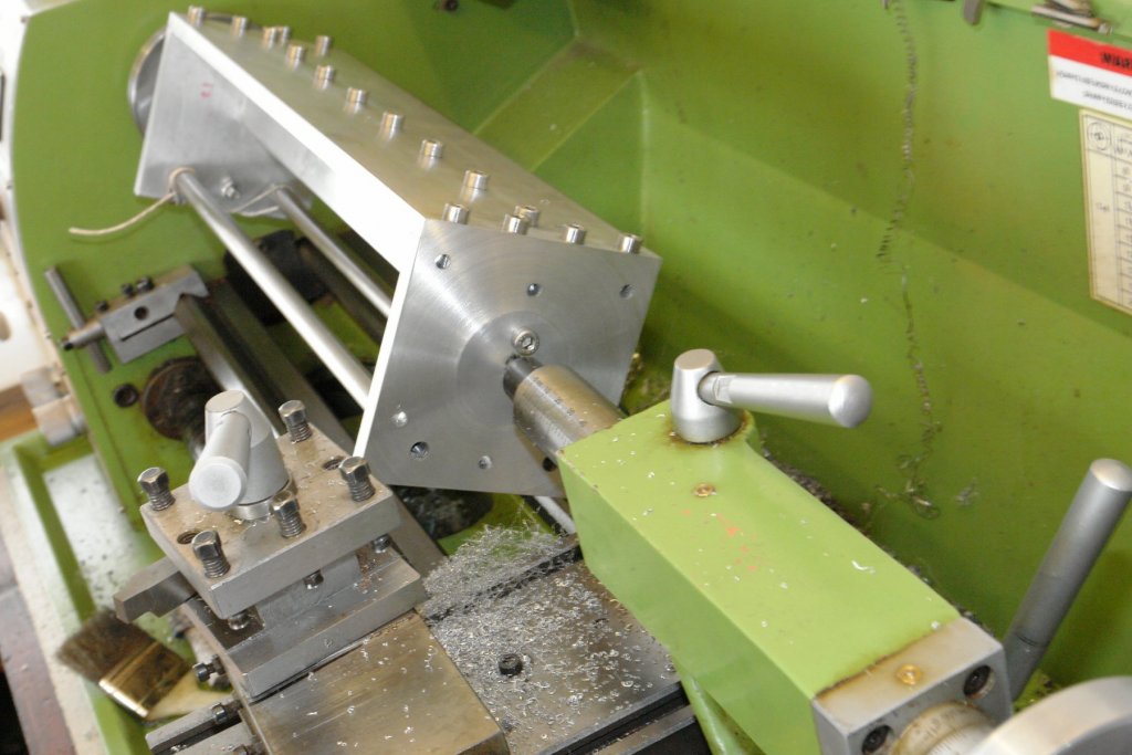
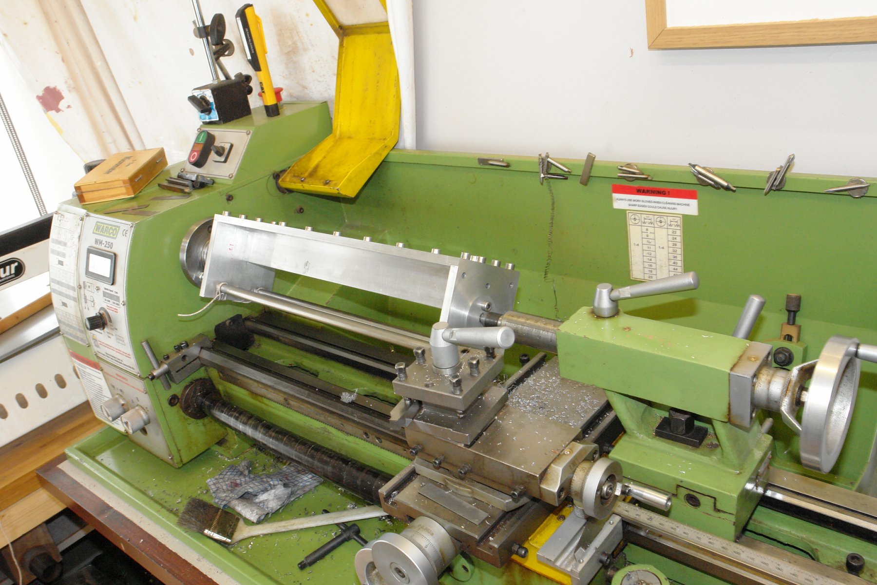
Today I did a bit more machining. Some time back I mentioned the need to have the column base at true right angles to the column axis. I had previously centre drilled holes in the top and bottom plate so the column could be mounted between centres on the lathe. The column is virtually at the limit of what my lathe will take in terms of swing over bed and distance between centres and getting it mounted took a bit of fiddling.
I started with the lathe chuck removed and the head stock centre installed. I needed to improvise a drive for rotating the column hence the bolt in the chuck mounting plate.
I bolted a piece of scrap to the top end plate of the column. The bolt in the chuck mounting plate bears against this.
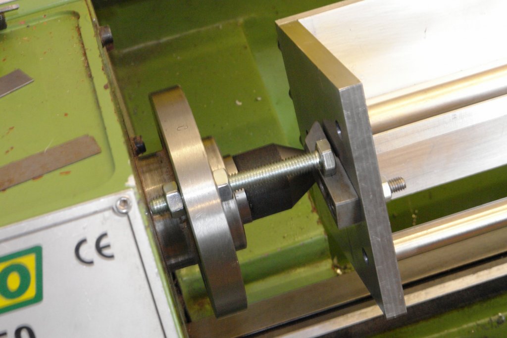
Because the column is much heavier on one side it had a tendency to "flip over" when rotated so I decided to lash it to stop this happening.

The saddle had to be wound right back on the bed as the assembly would not clear the saddle.
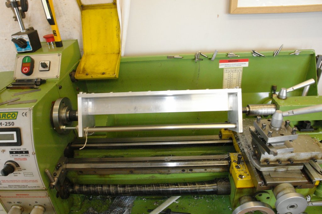
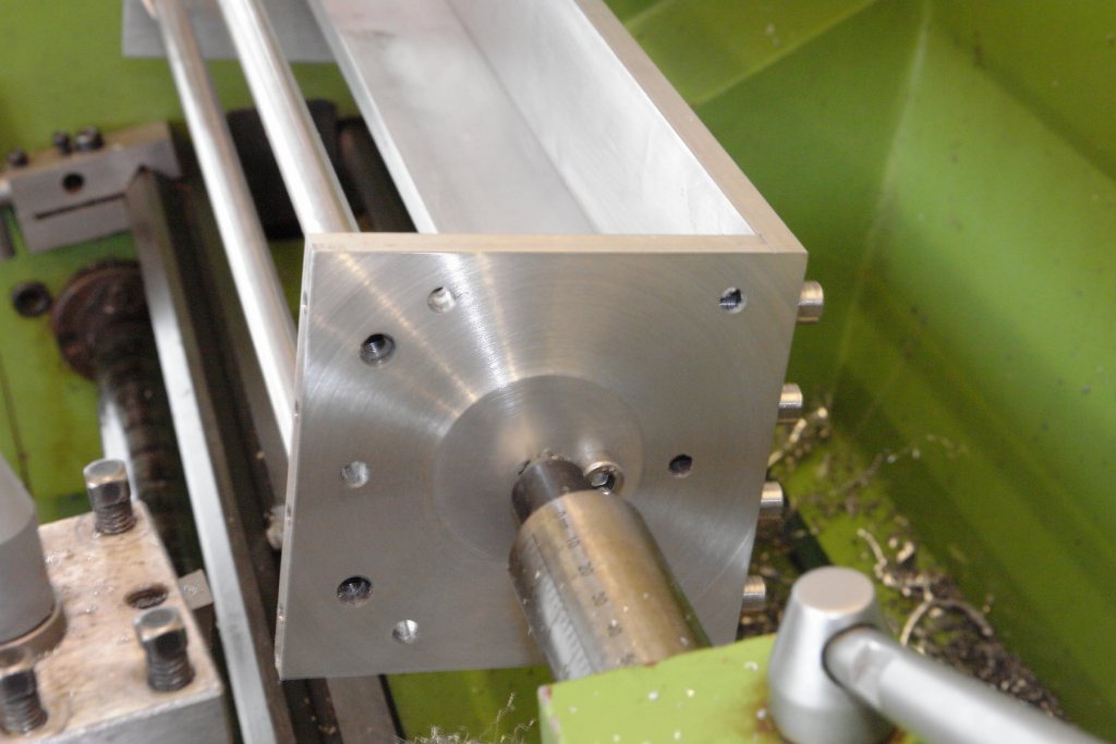
The speed of rotation for machining the lower end plate had to be very low - circa 100rpm. I tried it first at 200 and the lathe nearly jumped across the room. With this set up I machined the end plate. I don't have a power cross feed so the cross slide feed was turned very slowly by hand.

-
3 hours ago, shipmodel said:
The details are, of course, the only things that interest me in the photograph
You must be very old Dan or does the optivisor have a filter?
Funnels looking really smart.
- shipmodel, paulsutcliffe, Canute and 2 others
-
5
-
7 hours ago, michael mott said:
Will you be adding some rubber or leather wipers to keep the linear bearings clean of dust and swarf?
Hi Michael.
Thank you for your comments.
The linear bearing cages are held inside the bearing blocks by a pair of circlips, one each end. Between the circlips and bearing cages are a pair of rubber wipers. They look a bit insubstantial so I may upgrade them at a later date.
-
Hello Paul
Brave having 2 on the go at the same time. I find more than one stresses me out.
- Canute, Keith Black, paulsutcliffe and 1 other
-
4
-
2 hours ago, Old Mike said:
to say the least staggering and a huge help, or as I should say as an expat Yorkshireman "I'm gobsmacked".
Mike
There's nowt ere that tha can't do with a bit of elbow grease an nouce. Rimember "it's better to fettle an shaht abaht it nor nivver to fettle at all".
Looking forard t yer build log.
P.S. - i'm not really from Sussex.
-
Fantastic job on steering gear and light. Very impressive.
What is silkablock and where do you get it?
- mtaylor, John Allen, cog and 2 others
-
5
-
8 hours ago, wefalck said:
got one of those mechanical edge-finders,
Hello Wefalck
When I started my apprenticeship in the late 1960s we had never heard of edge finders. The method then was to wet a piece of cigarette paper and stick it on the edge. Then with the milling cutter rotating, wind the edge slowly towards the cutter. Just before the cutter touches the edge it wipes the paper away, thus establishing the position of the edge to less than the thickness of the paper, typically better than .001 inches. I now use a mechanical edge finder, but I may go back to how I learned to do it a half a century ago.
-
-
Derek / Wefalck - thank you.
Being away from the workshop at the moment I am having withdrawal symptoms. It has however given me time to have a bit of a think about the drive arrangement.
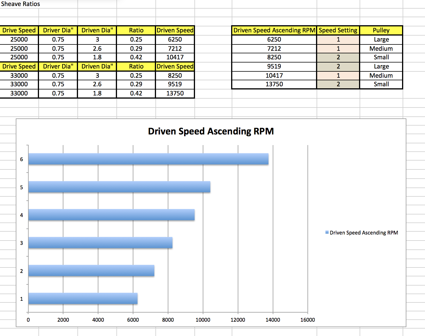
I have found it very difficult to get much information about the rotozip drive motor. The only information I have is what is on the body - i.e. 550W / 220v and switchable 25000 / 33000 rpm. The ratio of the speeds is almost exactly 1 to 0.75. I am therefore assuming that the motor is an AC synchronous motor with stator pole switching. This being the case I'm a bit concerned about the choice of variable speed drive - I guess I need to have the views of an electrical engineer. Views welcome??????????????
In the mean time however I have decided to put up with the limitations of the rotozip and deal with the speeds via a 3 pulley belt drive. With 2 motor speeds this gives me a total of 6 speed settings. Because I am working with the fixed ratio of motor speeds (1 to 0.75 as explained above) the speed choice is little compromised. However i think the following should be workable:-
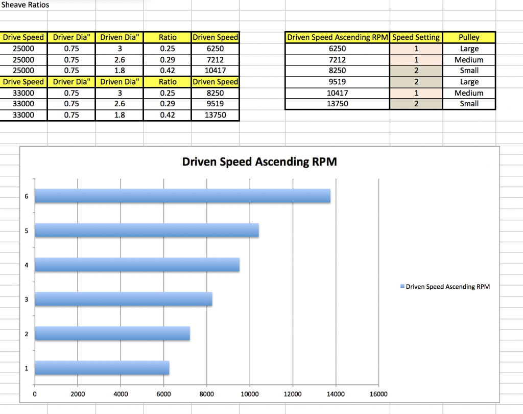
The pulley sizes are sensible at 0.75" driver and 3", 2.6" and 1.8" driven. I feel fairly comfortable with a cutter speed range between 6250 and 1375 rpm. I would however like a very low speed - circa 500 - 1000 rpm for use with a mechanical edge finder. Therefore I may come back to the VSD option at some time.
-
Derek, nice ship but glad whaling ships no longer find a use. Quite a gruesome business.
- Derek C, Tom E, Roger Pellett and 1 other
-
4
-
On 27/03/2018 at 12:41 PM, GSege said:
what would the preferred method of simulating the seams be? I have seen variants using pencil lead, wax crayon as well as acrylic paint.
Gunter - it’s a bit time consuming but my preferred method is covered in my Altair build (bottom of page 2 and then on to page 3) klick on the link below my name to find it.
-
-
Nicely done Nils- very neat.
- Mirabell61, Piet, popeye the sailor and 1 other
-
4


Home Made Mini Mill
in Modeling tools and Workshop Equipment
Posted
Michael, Druxey, Aviaamator, thank you for looking in and for your supportive comments re my recycling efforts. More to follow:-
I finished refurbishing the lead screw, reassembled it and mounted it in the column.
I had been giving some thought to the design of the milling head and in particular the type and arrangement of the bearings. Anyway the other night I was lying awake mulling it over when I remembered that I had a broken router in the garage. The router was little used in its first year - probably less than a couple of hours. Early in its second year it developed a winding fault and wouldn't self start. Its was just out of warranty and the cost of repair was nigh on the same as replacing it - so a replacement was bought and it found its way into the rainy day store. The speed and power rating was well in excess of my mini mill requirements and I thought the shaft, bearings and collet chuck would suit my purposes rather well.
Stripping down was relatively straightforward and soon the rotor and bearings were out.
Removing the rotor winding wasn't easy at all but it was eventual "hacked" off after an hour of sawing.
I did a redesign of the milling head after looking at the arrangement of a couple of commercially available mills.
I decided to make the bearing housing out of a 2"x2"X3.5" square aluminium bar. I ordered a piece for the purpose - 8 inch long and £13 from fleabay.
Chopping off the required length was another hacksaw marathon.
The cantilever stem supporting the bearing housing was cut from 2" X 1" aluminium bar from my metal stock. Both items were faced off square using a fly cutter. I love flycutting its so satisfying to see the almost mirror finish appear.
Its going to fit together something like this:-
There trick to making this work is to machine the bearing housing accurately - so that the shaft runs true. I took a lot of care when mounting the bearing housing in the mill. As bought the bar had a good surface finish and was square and parallel. I used a .0005" graduation dial gauge to check verticality on two adjacent faces. A lot of tapping with a hammer and checking and rechecking using the dial indicator finally got both vertical faces to within .0005" over the 3.5 inch length.
I drilled through the 3.5" length of the bar to take the shaft. A bit of a heavy job for my mill which complained quite a lot. This operation wasn't helped by my smaller twist drills being somewhat shorter than the hole being drilled. However eventually I got through.
I then had the job of opening out the ends to take the bearings. The bearings needed to be a very good fit so I took it real slow using my boring head - that is the head in the picture and not the head on my shoulders.
Having done one end I flipped the bearing housing over and went through the whole laborious process with the dial gauge once again. This time it took even longer - probably about an hour (although my wife tells me time is distorted in the black hole of my workshop). Each end has 4 holes which will take a plate that clamps on to the outer race of the bearings.
I managed to get the bearings nicely fitted with no slop.
I need to give a bit more thought to the arrangement of the belt drive - maybe in the early hours of tonight.