


KeithAug
-
Posts
3,867 -
Joined
-
Last visited
Content Type
Profiles
Forums
Gallery
Events
Posts posted by KeithAug
-
-
11 hours ago, Keith Black said:
build the stand in such a way that they are hidden.
Another good way to avoid the problem Keith.
- Keith Black and FriedClams
-
 2
2
-
13 hours ago, Stephen Allen said:
Or, left a friction fit or a rare earth magnet at the top of the mounting post so you have a choice?
Great "I can't make my mind up" option Stephen.🙂
- Keith Black and FriedClams
-
 2
2
-
-
7 hours ago, Keith Black said:
I'm going to get out my 1/2 inch cordless lathe and see if I can successfully turn a potbelly stove.
Should be an interesting turning project Keith and I could always make you one if need be.
- Canute, FriedClams and Keith Black
-
2
-
 1
1
-
17 hours ago, Jim Lad said:
you really have no other choice but to include the stabilisers.
Yes John - I know the logic. Am I the only one that thinks they look incongruous on a 1901 shaped hull?
- yvesvidal, FriedClams, Keith Black and 1 other
-
4
-
On 2/16/2025 at 1:45 PM, Veszett Roka said:
If my vote counts, i'd go for full unpainted wooden hull.
All votes will be counted Veszett.
On 2/16/2025 at 4:04 PM, yvesvidal said:I think it needs an extra coat of clear
I think you may be on to something there Yves.
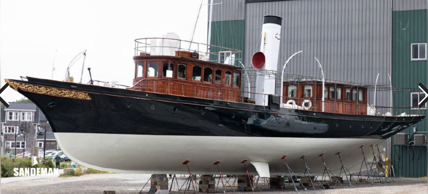
Not wanting to jump to a snap decision on paint finish I diverted to another controversial area. I refer to the stabilisers. Clearly they were not a feature of the 1901 build and were presumably included in the 2007 rebuild to make her more comfortable for the more delicate sailors of the 21st Century.
I personally think Cangarda looks quite odd with the stabilisers fitted but unfortunately I can't bring myself to omit them (departing markedly from her rebuilt form).
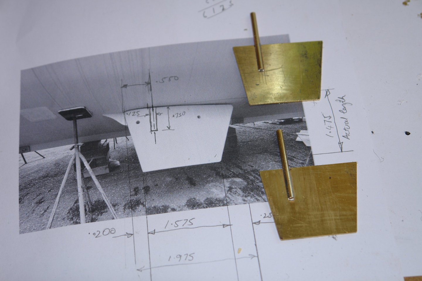
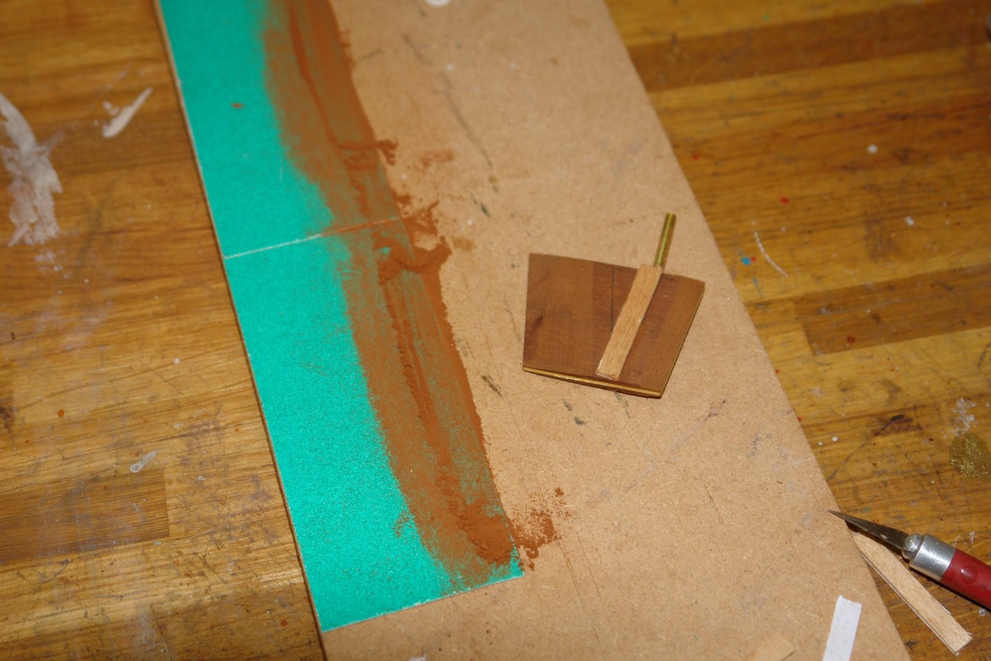
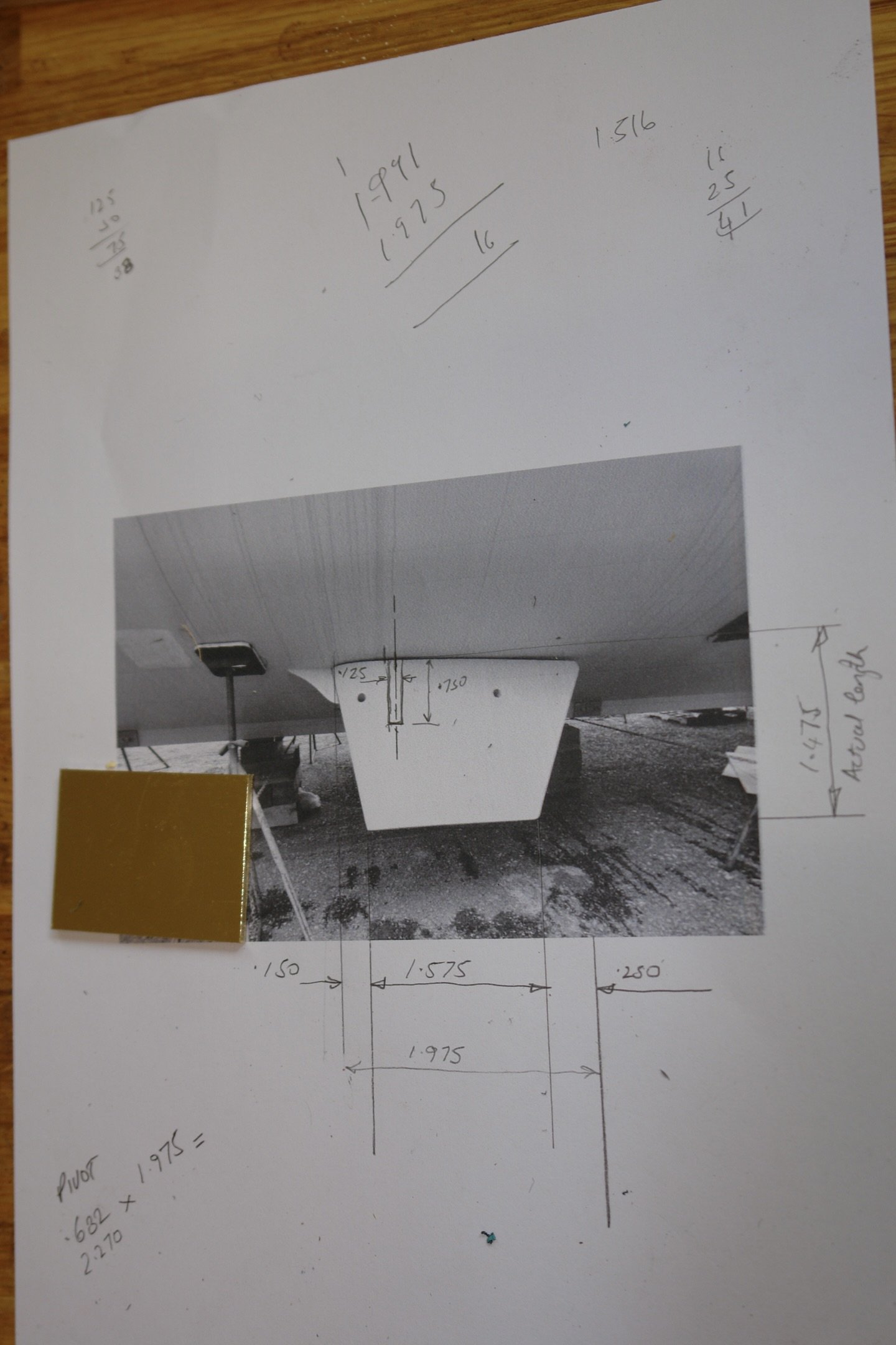
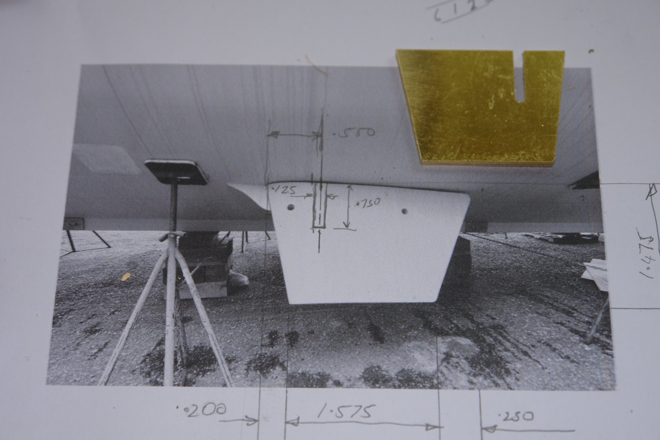
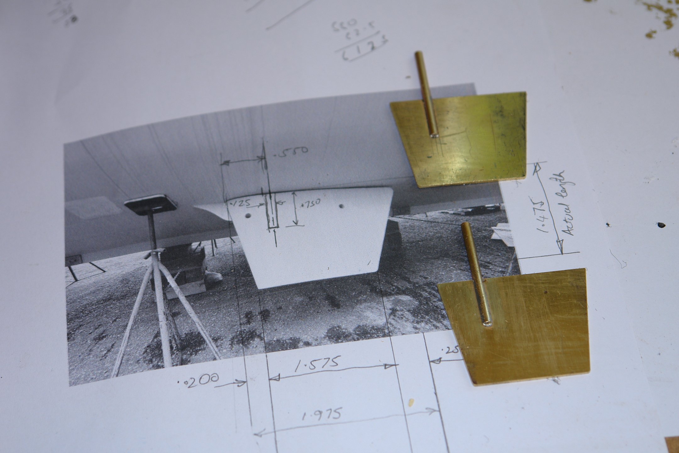
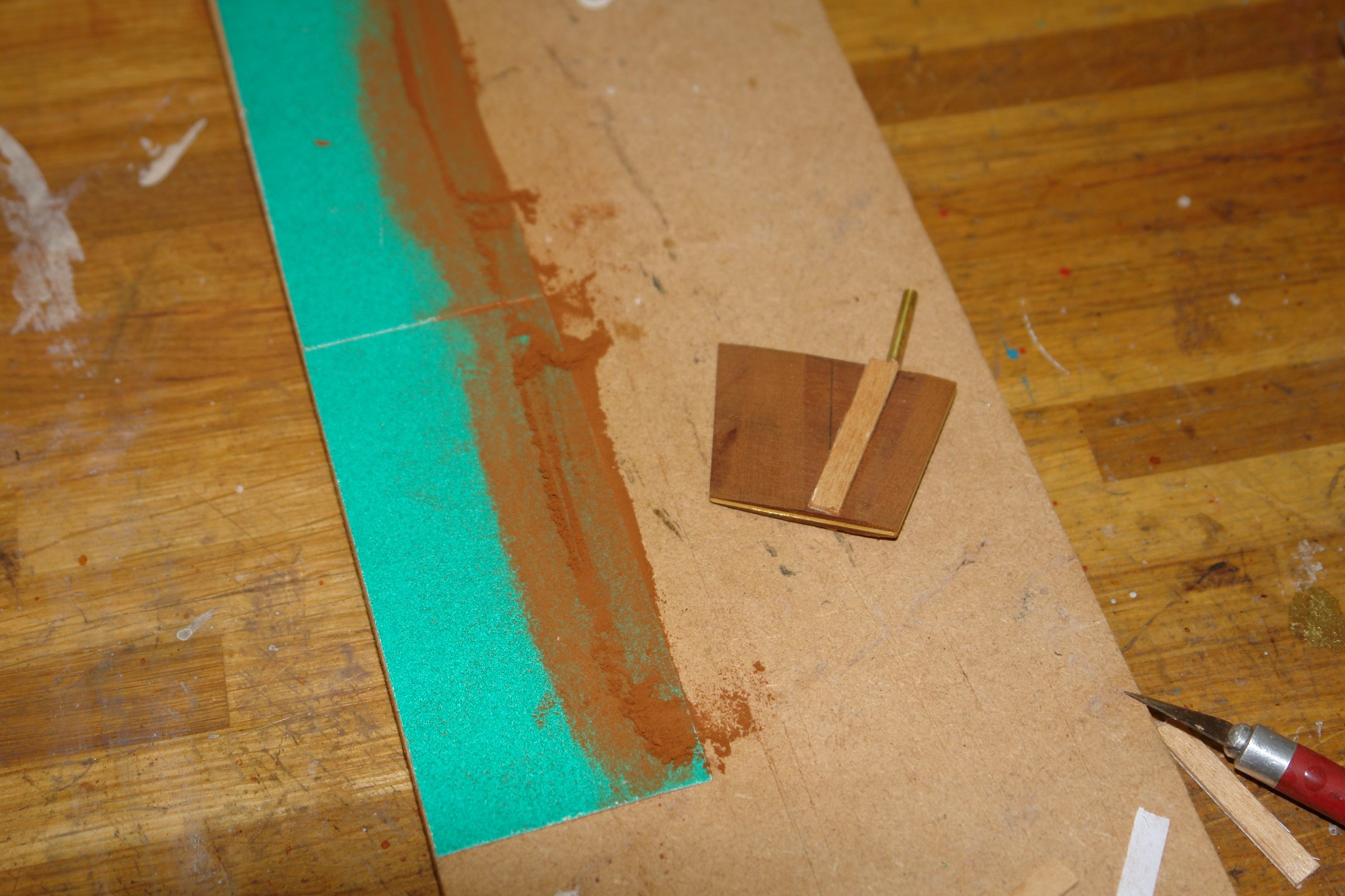
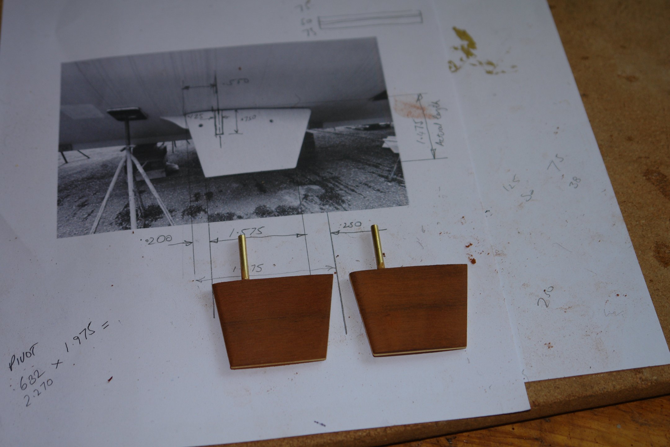
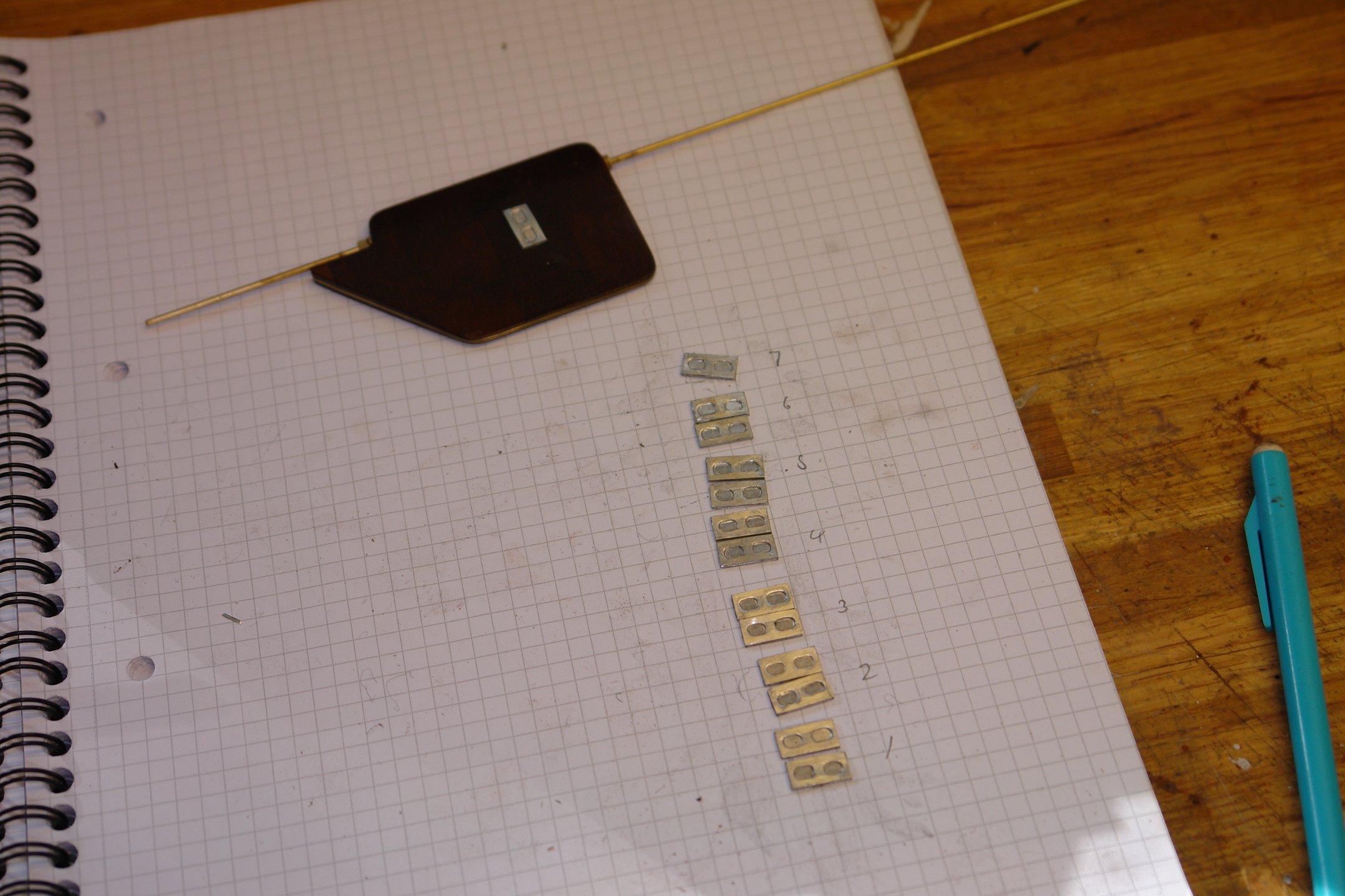
Courtesy of Rick I have some rather good shots of the stabilisers and these plus a bit of educated scaling allowed me to do a reasonably good job of getting their size and shape correct. As with the rudder, I am making them from a brass core clad with mahogany. The next shot shows the dimensions and the already cut brass plates (1/16" thick). The 2 plates are held together with double sided tape at this stage.

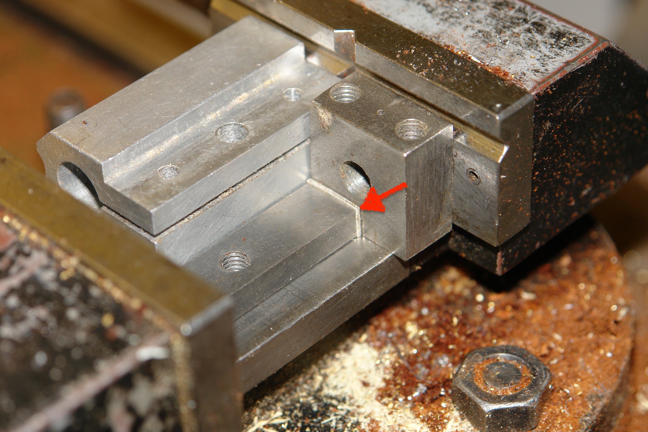
The plates were then cut to shape and a 1/8" slot was milled out for the shank.

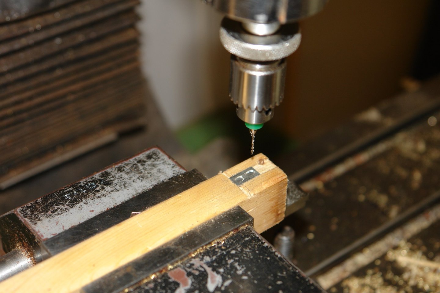
The 2 plates were then separated and the shanks were cut from 1/8" brass rod.

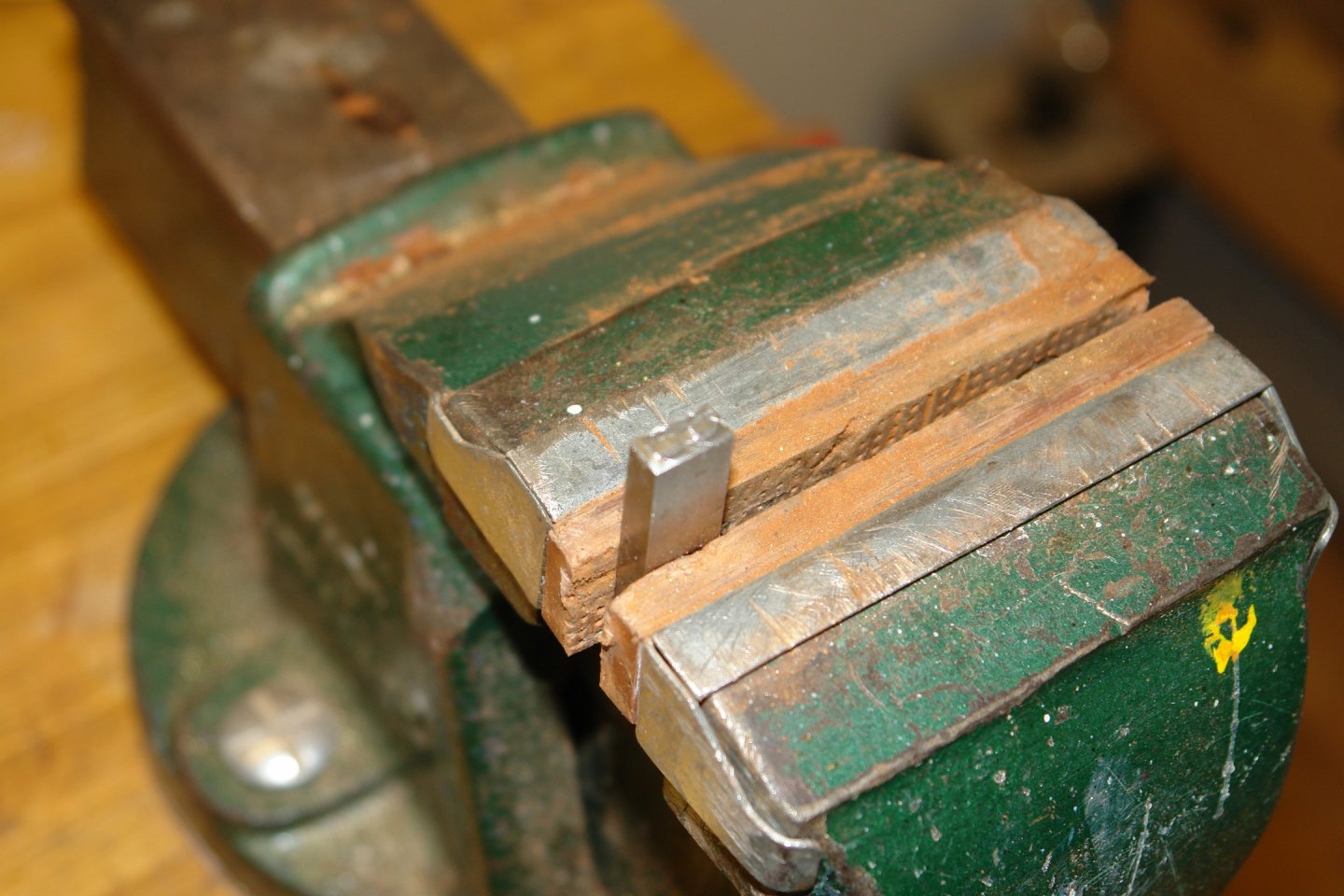
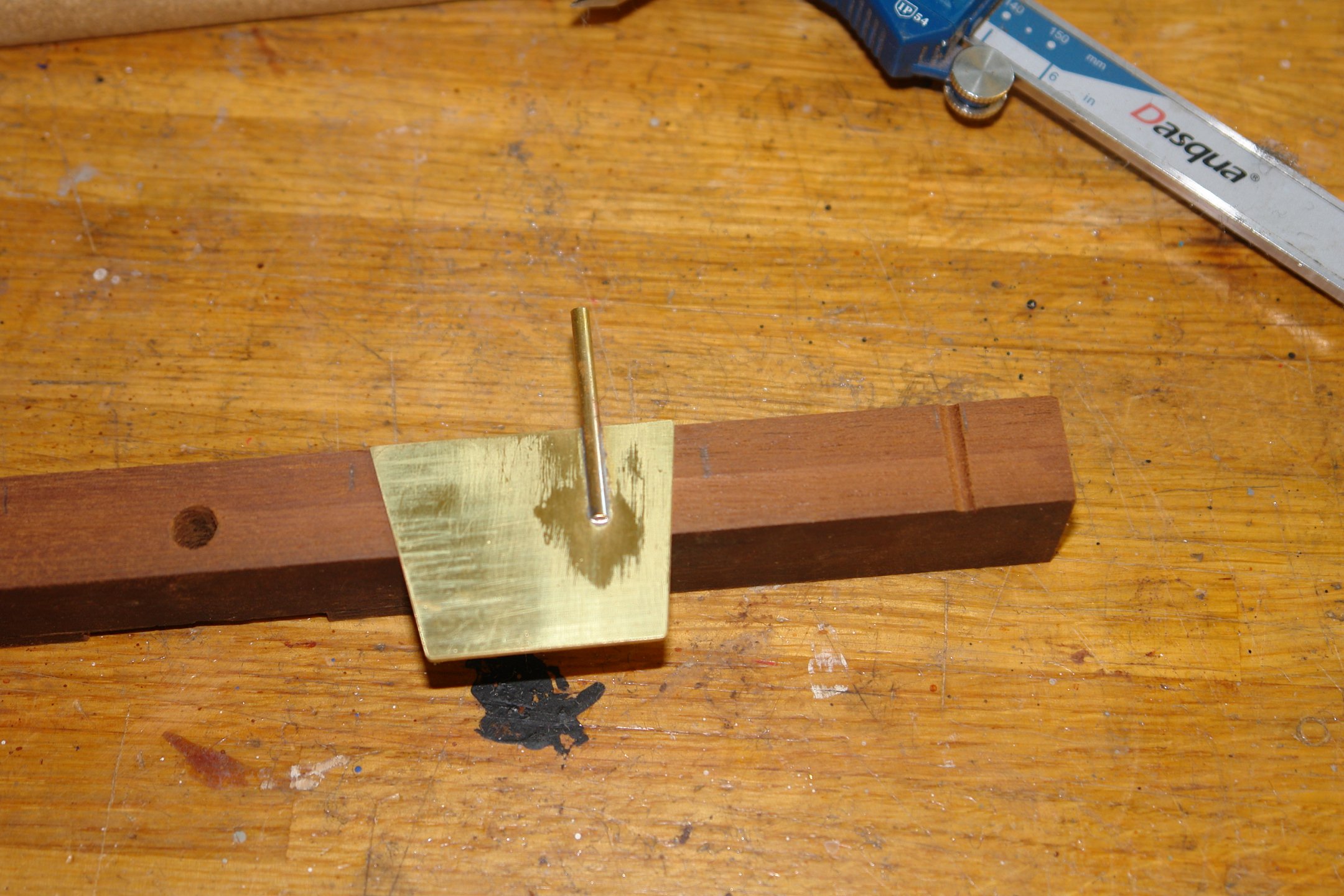
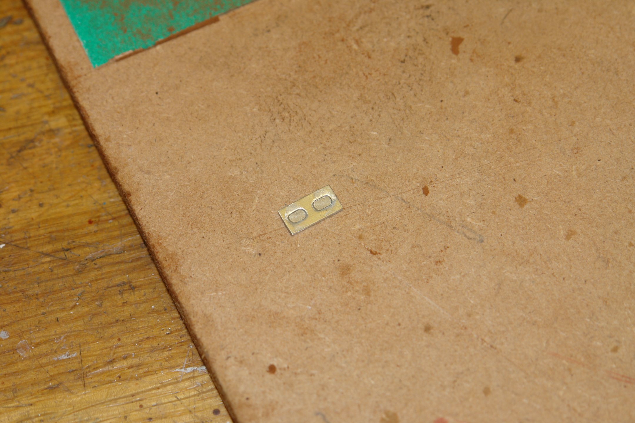
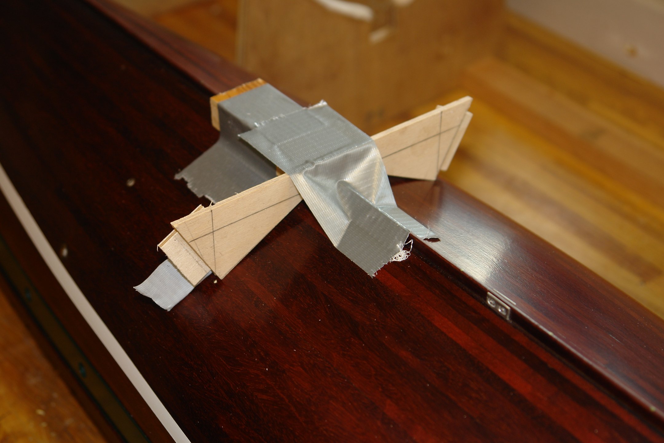
The shank needed to be soldered central to the plate, so for soldering stage the plate was supported on 2 off 1/32 twist bits (as per the next photo).
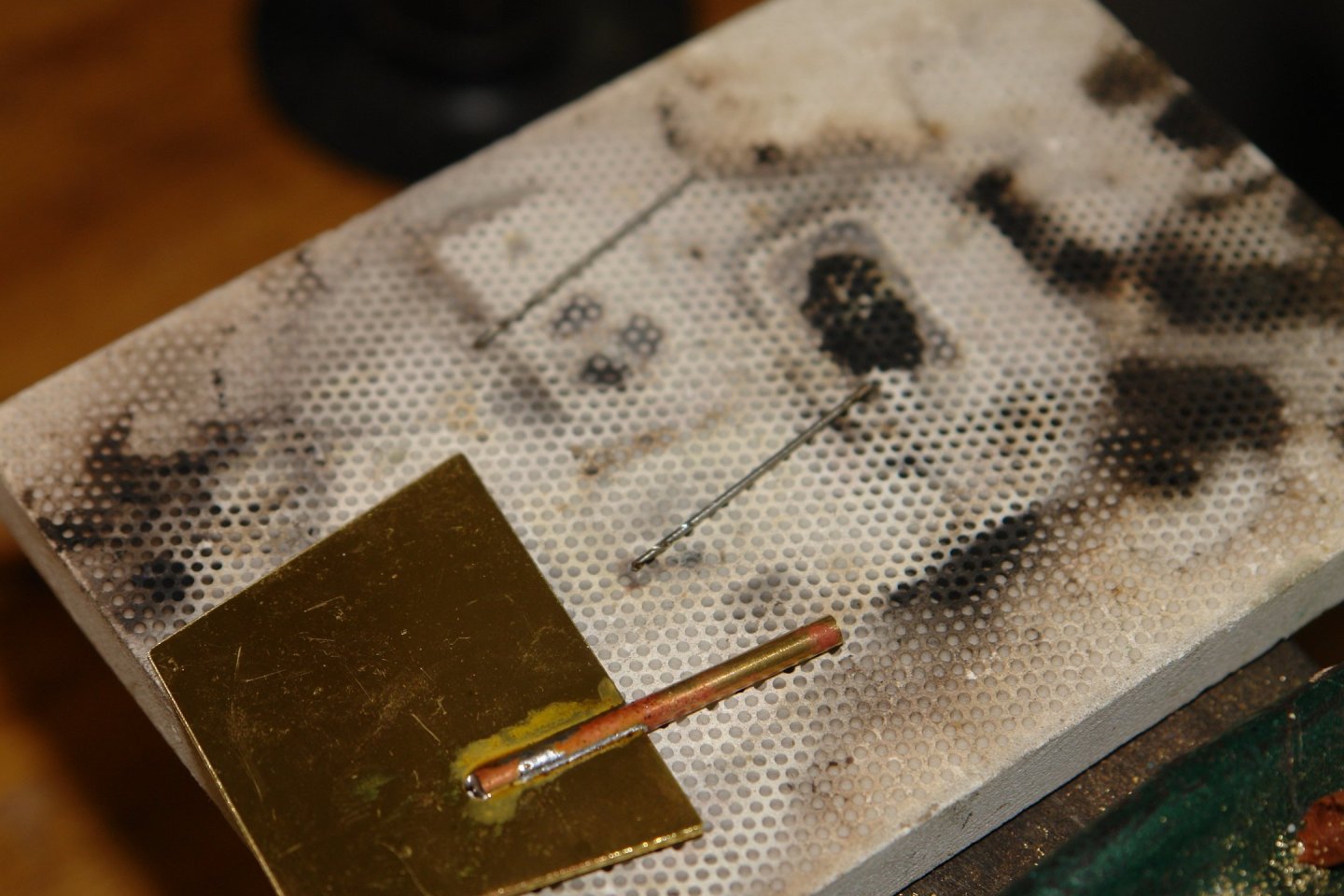
The solder was then cleaned up.
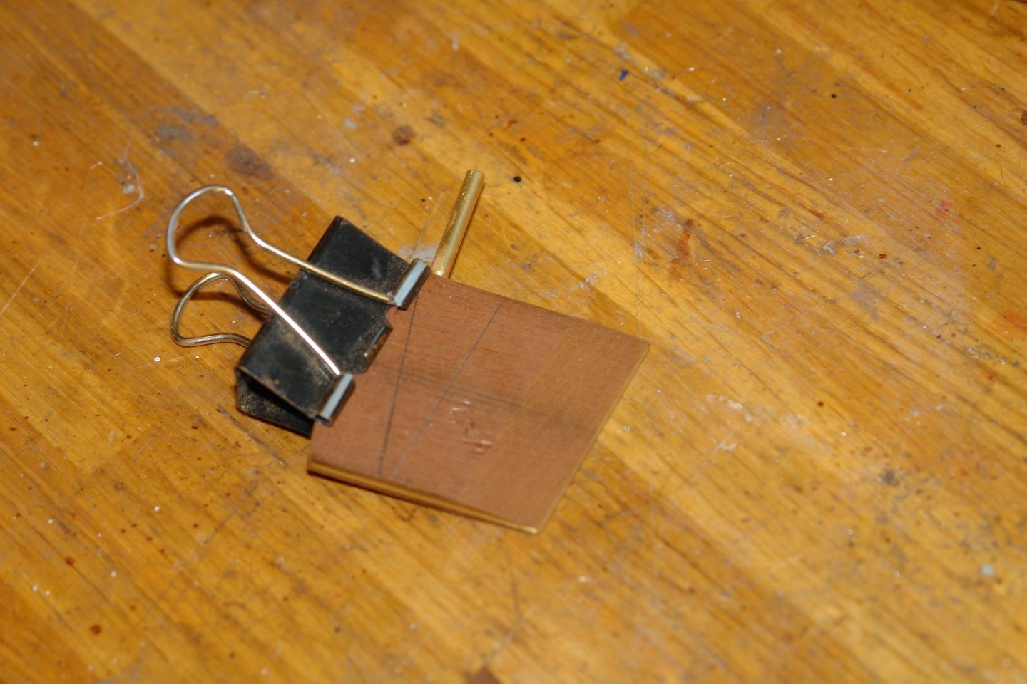
Mahogany planks were then glued to the brass - note the slot in the mahogany to take the shank.


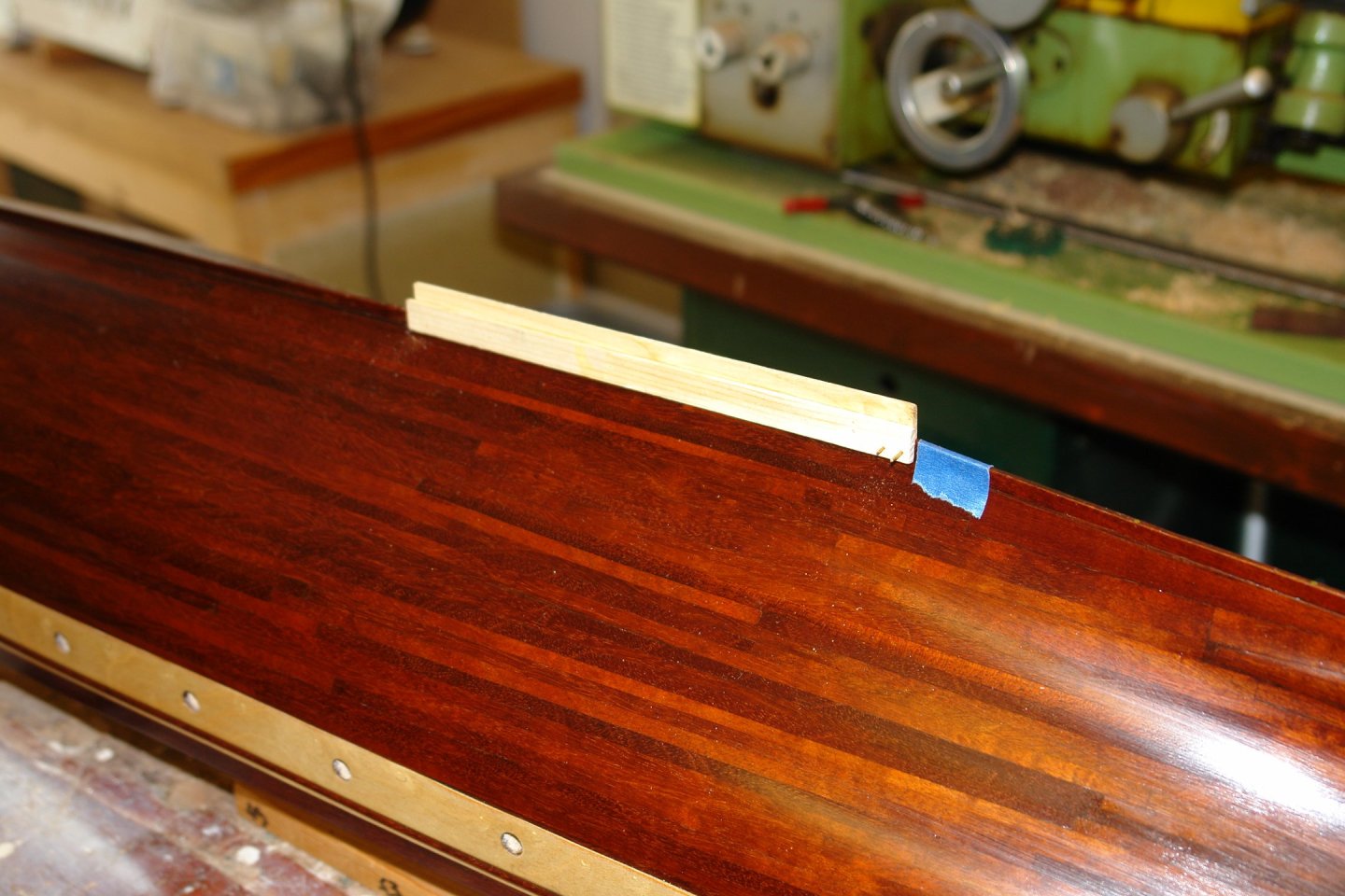
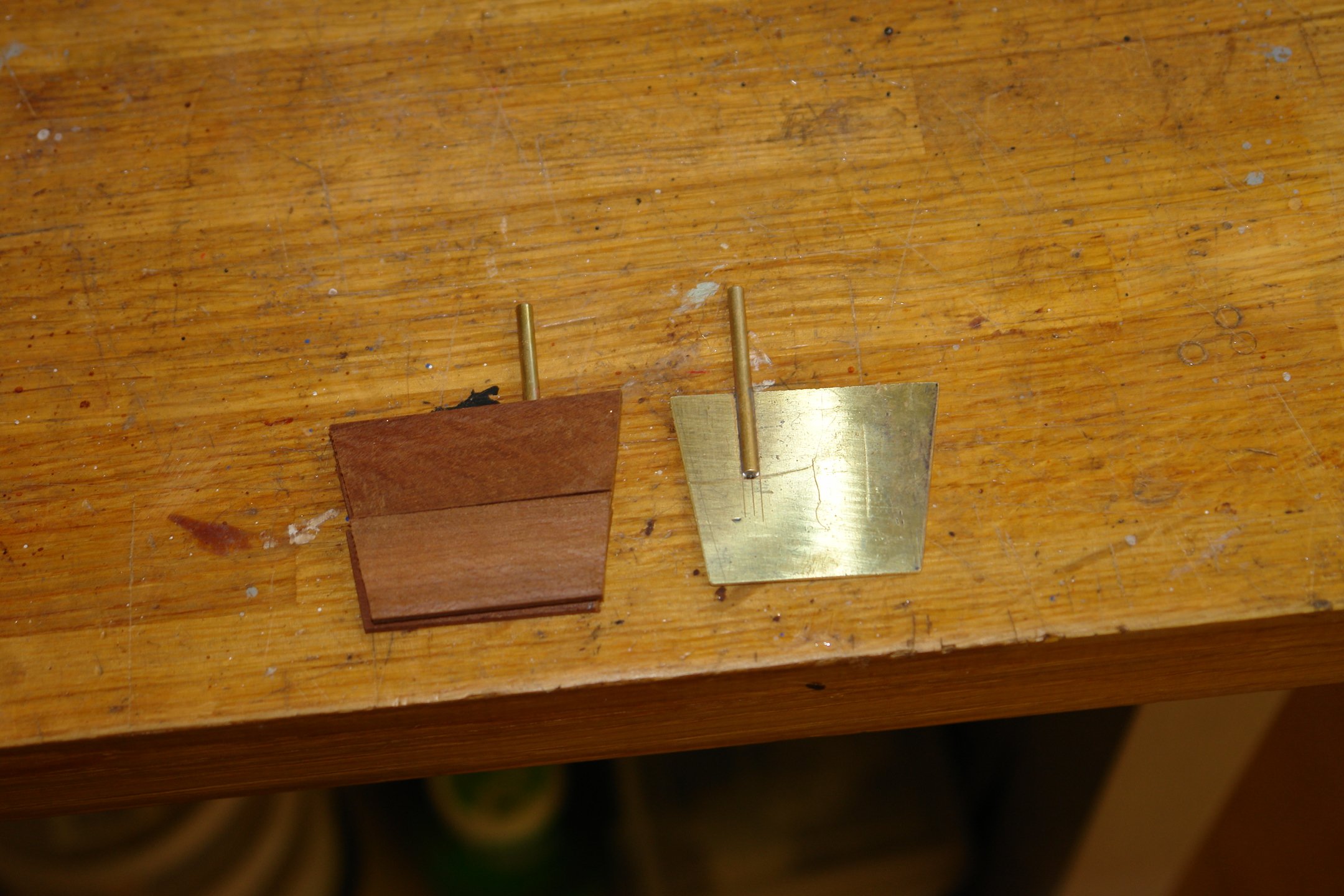
Once the mahogany was secure I used my patent bulldog clip method to control sanding of the aft end taper.
The front end needed a slightly different approach because of the trapezoidal shape. In this instance I temporarily attached a sacrificial strip with double sided tape.
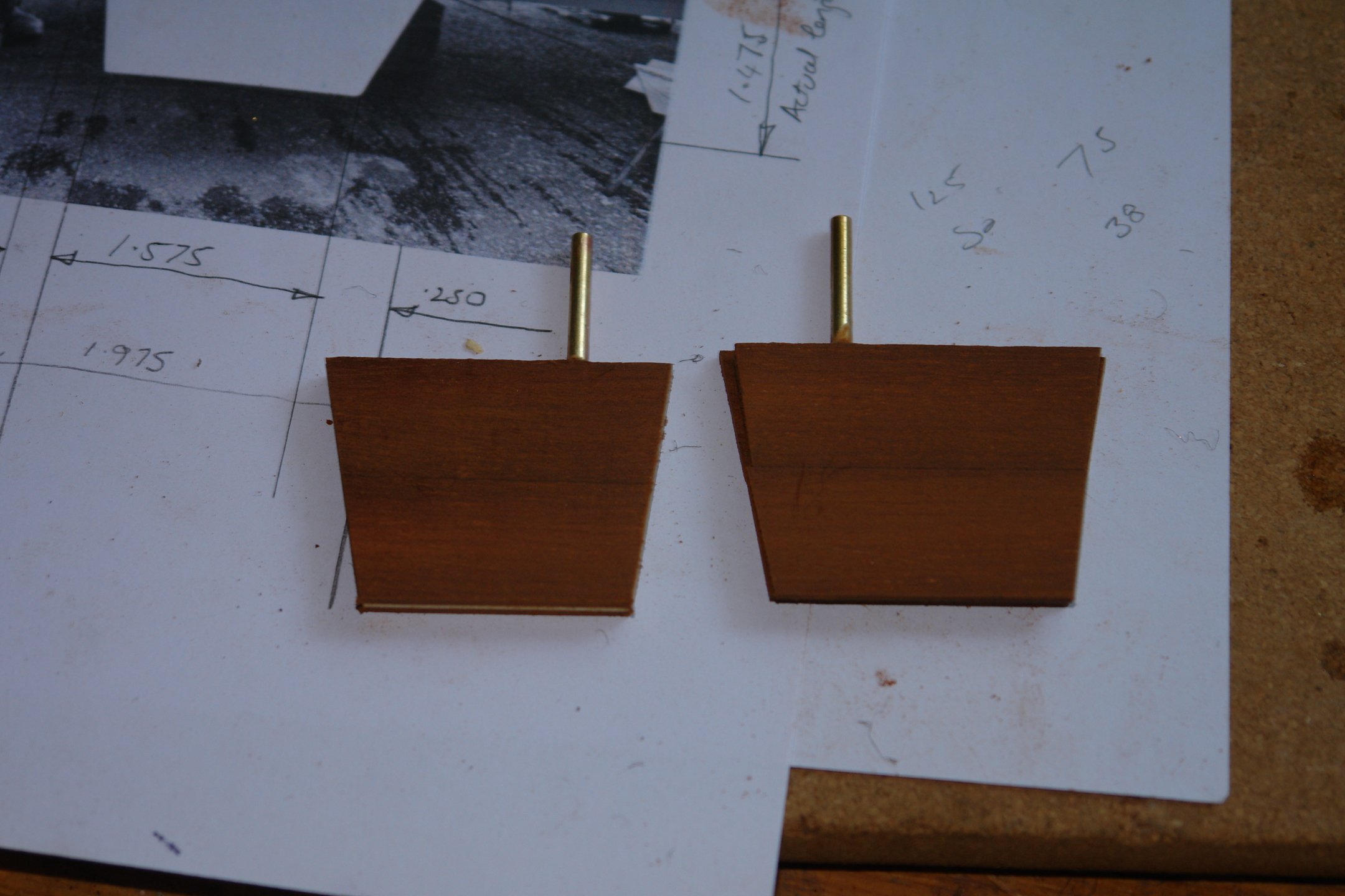
The two stabilisers were thus completed.

I now plan to move on to sorting out the hull paint scheme.
- mikegr, FriedClams, FlyingFish and 11 others
-
13
-
 1
1
-
17 minutes ago, LJP said:
You can also look for a chimney in the pilot house roof.
There does not seem to be any chimney - a steam pipe or two would seem to be the obvious solution - probably using exhaust steam.
- FriedClams, Keith Black, Ian_Grant and 4 others
-
6
-
1
-
The stern wheel looks excellent Keith.
- FriedClams, Keith Black, Canute and 1 other
-
3
-
1
-
47 minutes ago, Wreck1919 said:
The first boat/davit assembly is done.
Really smart and realistic. Excellent.
- eatcrow2, Keith Black and Canute
-
3
-
16 hours ago, Greg Davis said:
but the bends need to be done without so much damage to the wire.
Greg
If the copper is hard soften it by heating (to red) and then quenching - this should make it very easy to bend, then it should be possible just to bend it by hand around a piece of metal rod of appropriate diameter.
- Greg Davis, AON, druxey and 2 others
-
5
-
On 2/14/2025 at 6:32 AM, JacquesCousteau said:
Unfortunately, it looks a bit odd to only have it in the middle of the hold, and it's pretty visible how it just ends when it reaches the bulkhead, spoiling the illusion of a cargo load.
What sort of cargo would she typically carry? It would be nice to try and show it.
-
Thank you Keith - I couldn't see it either.
- Greg Davis, Keith Black and Canute
-
3
-
23 hours ago, Veszett Roka said:
what are you planning below the waterline?
Veszett - Natural wood. Although above the waterline is a little more uncertain at the moment.
Phil / Keith - your passion for detail is a constant source of wonderment.
- Keith Black and FriedClams
-
2
-
47 minutes ago, Veszett Roka said:
But, if the hull is depicted as wood,
Veszett, they are anti shipworm anodes.
- Keith Black, Ian_Grant, Veszett Roka and 1 other
-
1
-
3
-
3 hours ago, Dr PR said:
Guinness World Records for applying the most coats of finish
54 minutes ago, Keith Black said:I think he owns stock in the company.
32 minutes ago, Jim Lad said:Someone confiscate his tin of poly!
25 minutes ago, Keith Black said:Mrs Keith probably wouldn't appreciate us doing that
Shock horror - the tin is nearly empty. I spent happy hour on the web a few days ago looking for a replacement. The question is 75ml, 1000ml or 2500ml. What do you recommend noting the trend to phase out oil based paints?
Thank you Vossiewulf.
- Keith Black and FriedClams
-
2
-
On 1/20/2025 at 4:52 PM, Keith Black said:
I was in recovery when yesterday I slipped on the icy back steps taking out the trash.
Oh dear, you do need to take care. We young things bounce quite well but at your age it pays to be super safe. 🙂
I have enjoyed catching up, you have been such a busy boy. All looking rather magnificent.
- Canute, Glen McGuire, FriedClams and 1 other
-
3
-
1
-
John - Yes the Robert E lee overhang is quite remarkable. Hopefully the passengers won't be running side to side to see the sights.
- Keith Black, John Ruy, FriedClams and 1 other
-
1
-
3
-
Yes - good luck George. I think you are right not to increase interview stress by being too dependant on public transport.
- Keith Black, gak1965 and Canute
-
3
-
-
Thank you Pat, Rick, John, Keith, Druxey, Veszett and Ian - and of course the rest of you have liked my work.
On 2/10/2025 at 3:17 PM, Ian_Grant said:Modern water-based finishes definitely take more coats to "build" than the old stinky stuff.
Yes Ian - I still use the old stinky stuff but still managed 14 coats - however see below!😬
On 2/10/2025 at 1:33 PM, Rick310 said:what was the thickness of the brass you used for the trail boards?
Rick - very thin to ease cutting - about 0.010"
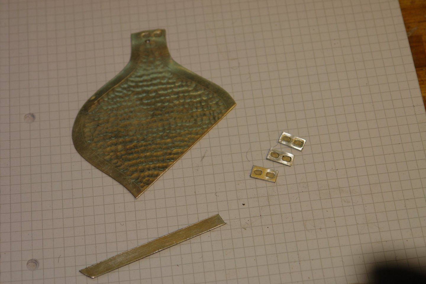
I set about making the anodes of which Canada has 14.
I wanted to give them a bit of shape so I decided to try pressing them. I started by making a press tool from mild steel. This was partially milled and finished by hand filing.
I used the machine vice as a press.

With a bit of cleaning up the first one turned out acceptable.

The pressed metal was quite soft - it is actually an old decoration that used to be a Christmas decoration. I think it might actually be a zinc alloy which seems quite appropriate.
Here are all 14.
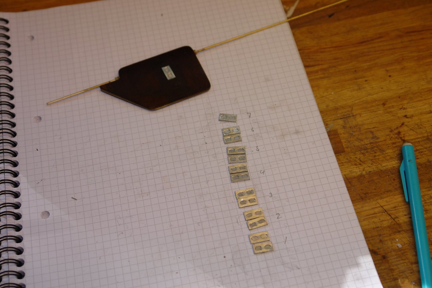
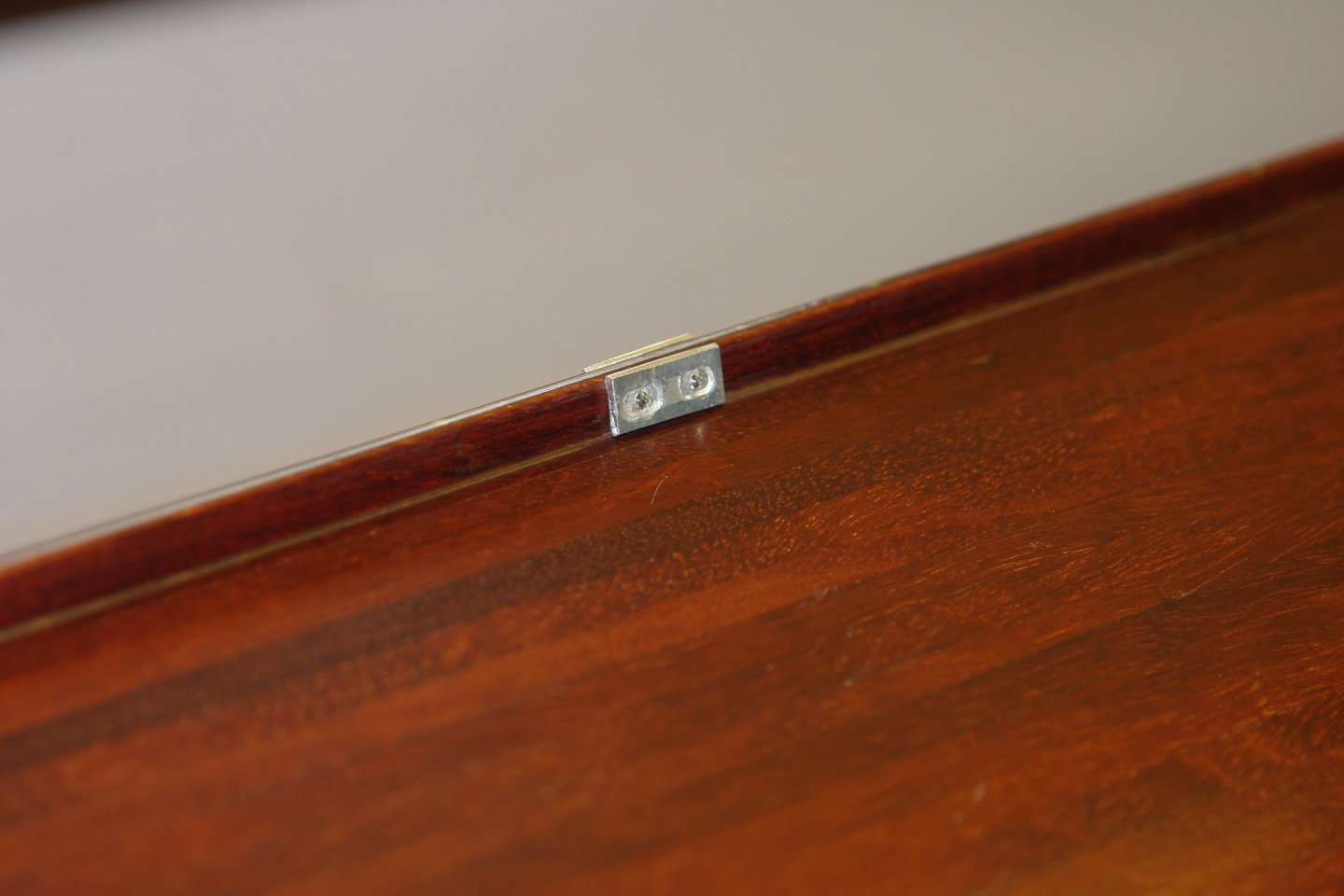
All were drilled with 2 holes to take the mounting bolts. The slotted piece of wood is a crude locating jig to make drilling quicker.
The keel was drilled through to take the anodes (symmetrical on either side)

Then glued and screwed in place.
The anodes are spaced equidistant along the keel - so again I made a simple jig to assist drilling of the holes.
I then used my previously made jig to drill the stabiliser holes. I always put off drilling holes in the hull - I think it is fear. You can see the jig has been modified to give better angular control of the drill. The Jig was taped securely to the hull and the holes were drilled with my heavy duty hand drill.

All was well.

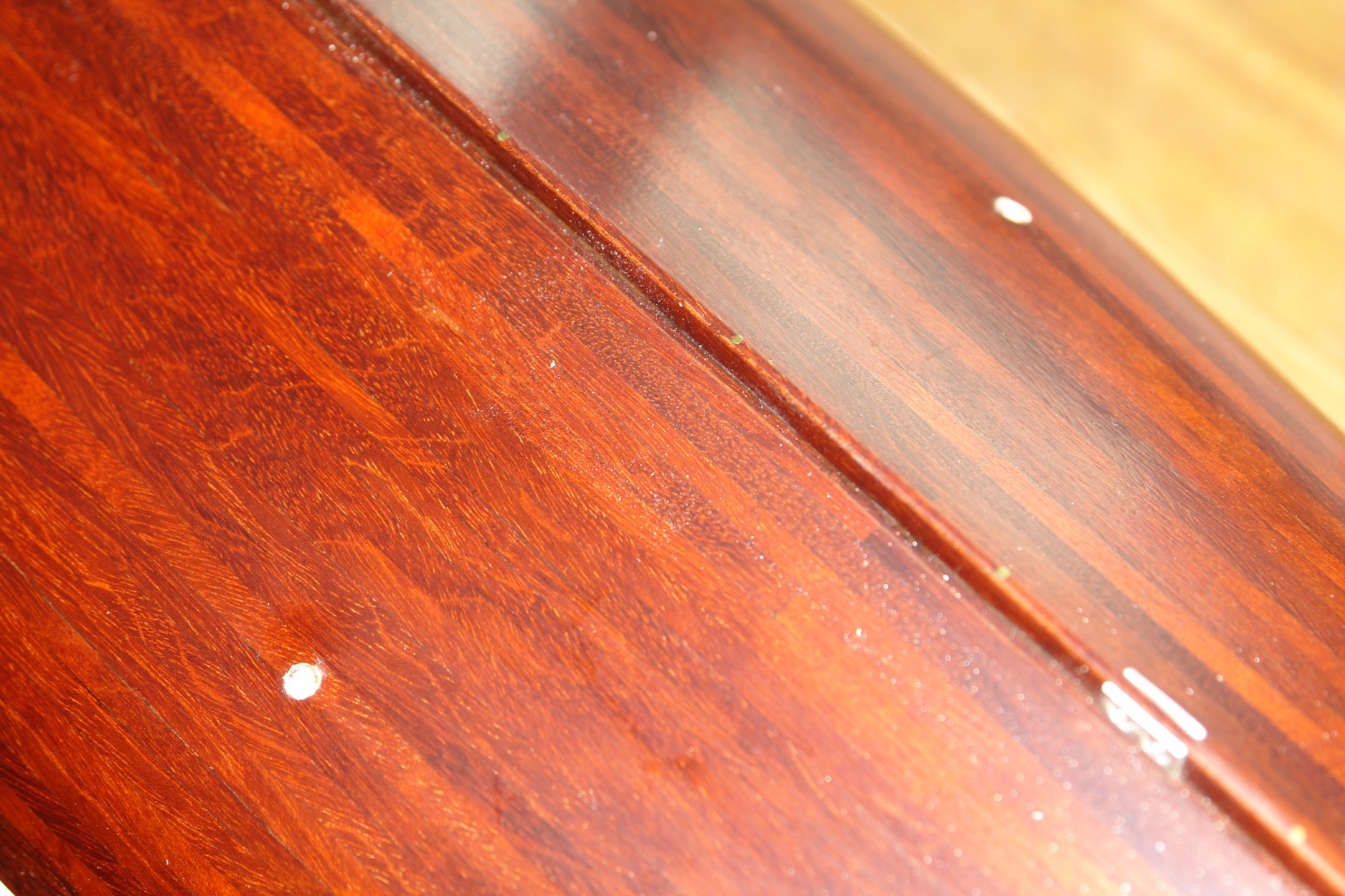
Fortunately no damage to the paintwork ---------- but then ! succumbed and 2 more coats of Poly went on. Compulsive or what!!!!!!
Ant then another go with the super fine wire wool.
Somehow the final 2 coats seemed to help. The sheen was quite subdued and the finish was reasonably uniform which pleased me.
The next job is making the stabilisers and thereafter masking up for the spray paint job.
That's all for now so back to catching up with all your builds.
- Wintergreen, yvesvidal, Dr PR and 12 others
-
15
-
-
On 1/20/2025 at 9:24 AM, Mark Pearse said:
The first few days are obvious exposed to the south & south-east. But assuming the weather is ok, it should be really good,
It looks like a wonderful Trip Mark. Not sure why you are worried about southerlies and south easterlies - they were the best winds in the Outer Hebrides.🙂
- Jack12477 and Mark Pearse
-
2
-
I am very anti 3d printing, basically because I'm too lazy to learn how to use it. If I can get over this hurdle I am going to become its number 1 advocate.🙂
-
On 1/21/2025 at 11:38 PM, Keith Black said:
Those of us without 3D printers and the ability to use them may as well be living in the stone age,
Don't worry Keith we may be heading back there.
- Keith Black and Canute
-
1
-
1


Cangarda 1901 by KeithAug - Scale 1:24 - Steam Yacht
in - Build logs for subjects built 1901 - Present Day
Posted
Rick - that was always going to be the plan but as time goes by I am refining it. Indecision is the sincerest form of procrastination.