KeithAug
-
Posts
3,986 -
Joined
-
Last visited
Content Type
Profiles
Forums
Gallery
Events
Everything posted by KeithAug
-
 The shaping is going really well Tom, not bad for a first scratch build. I find my mind can wander in almost any situation.
 -
She is coming along very quickly Allan. Are you working to a deadline or are you just naturally quick? Not sure you should have used that piece of walnut, now it won't be available for some future use.
-
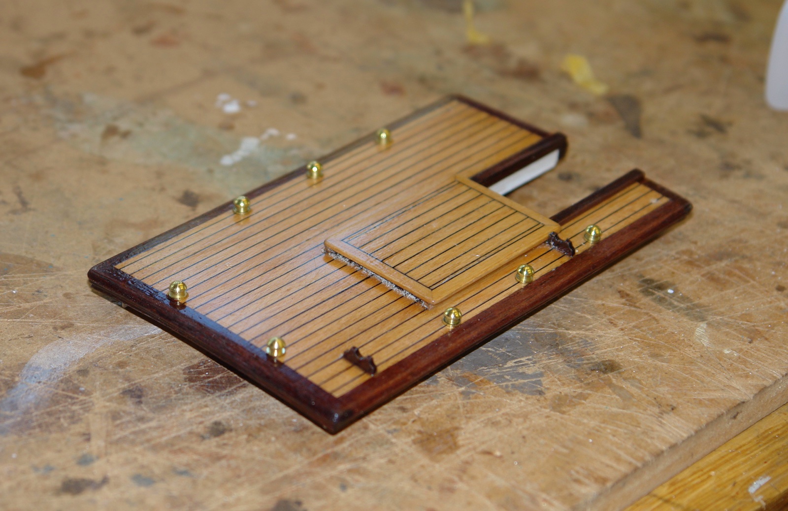
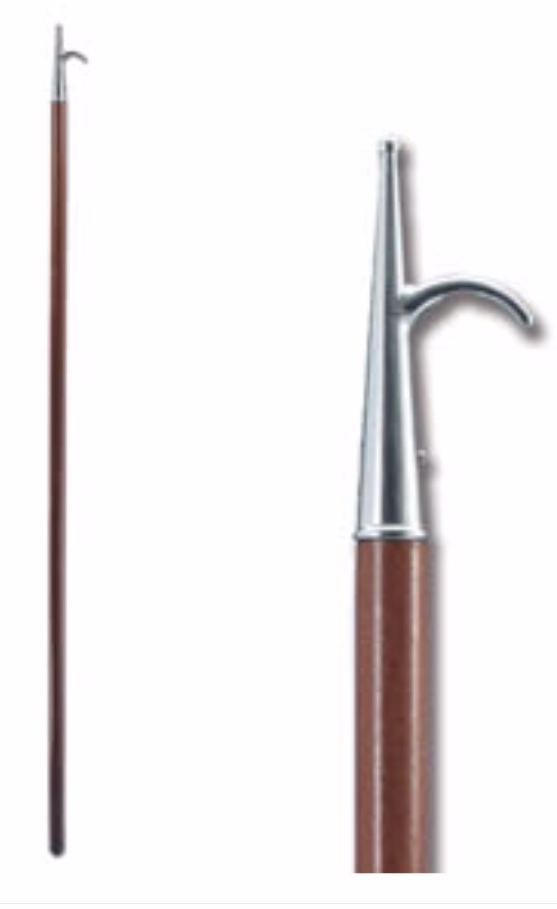
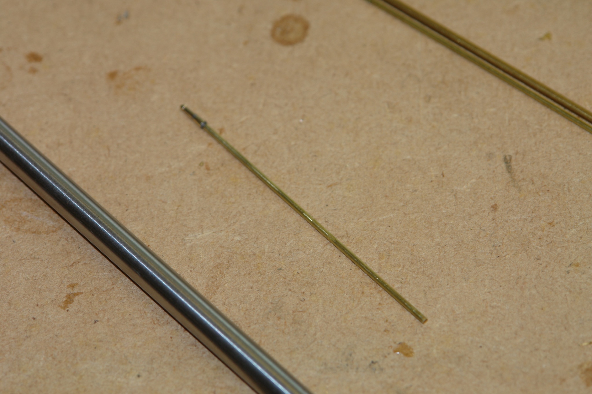
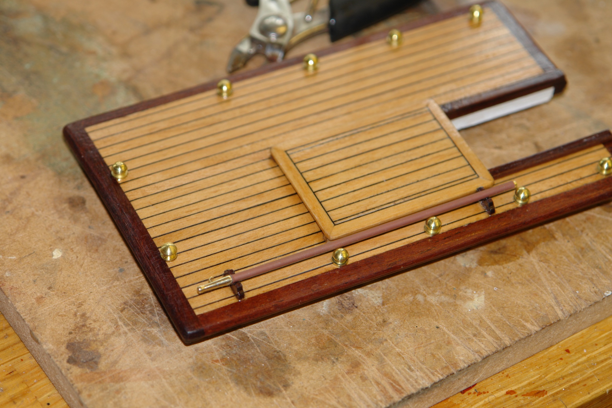
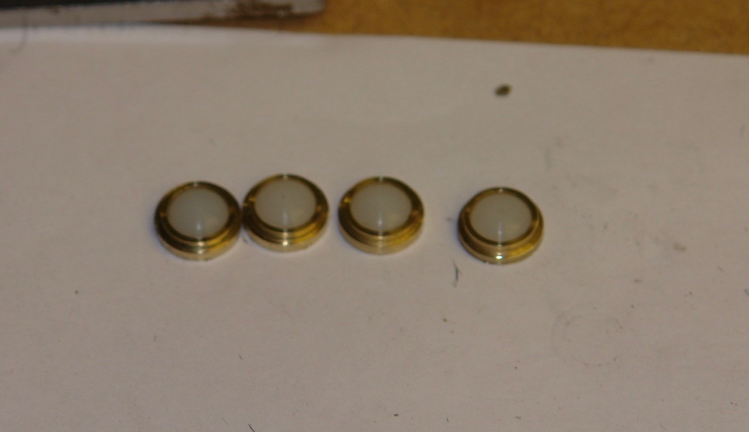
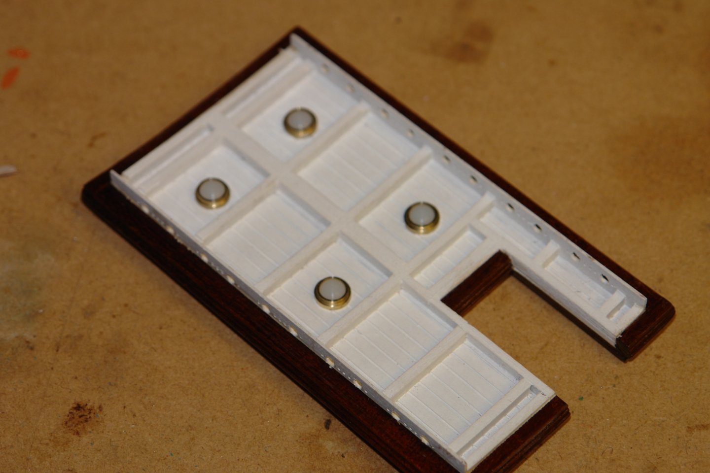
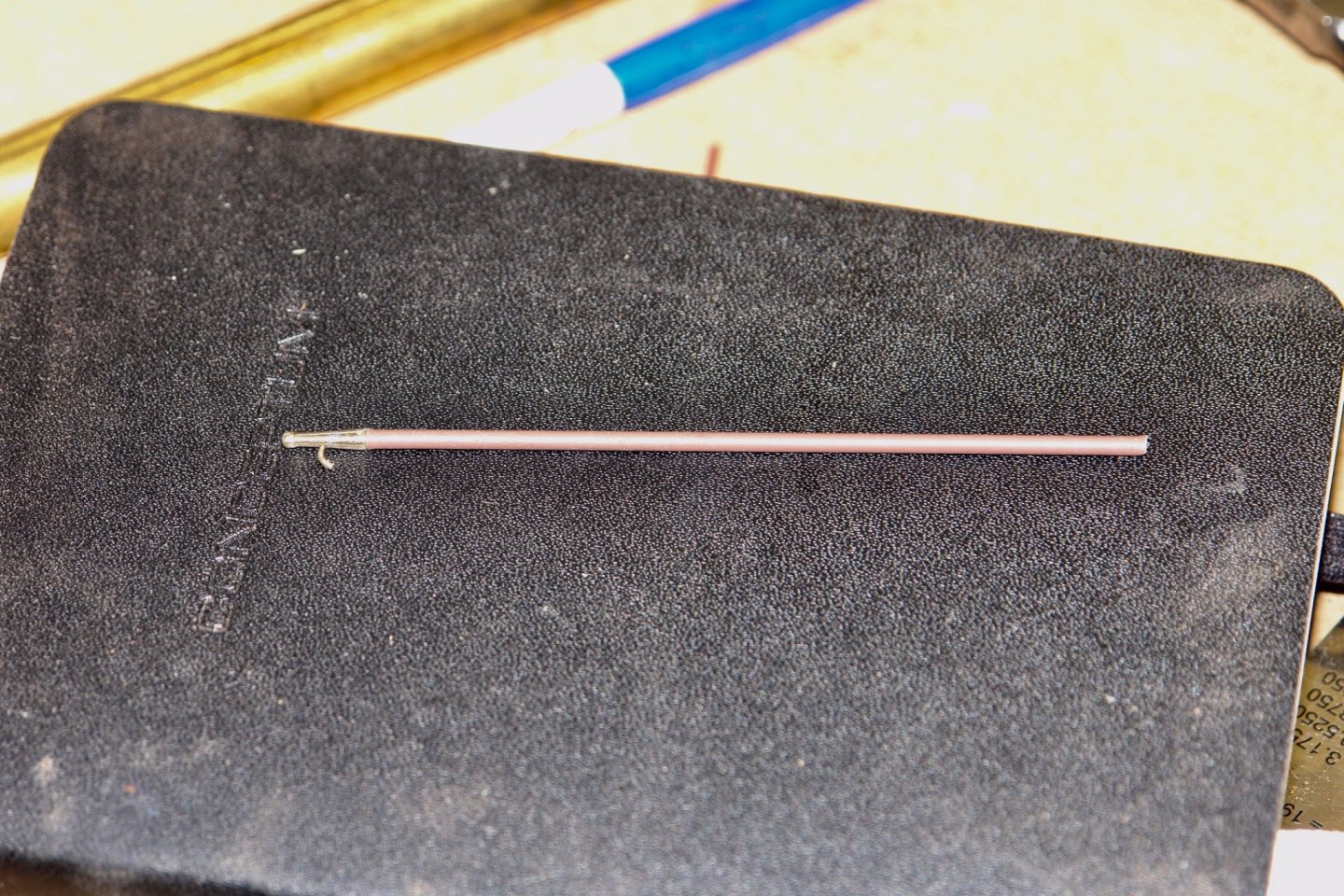
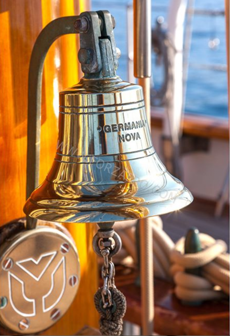
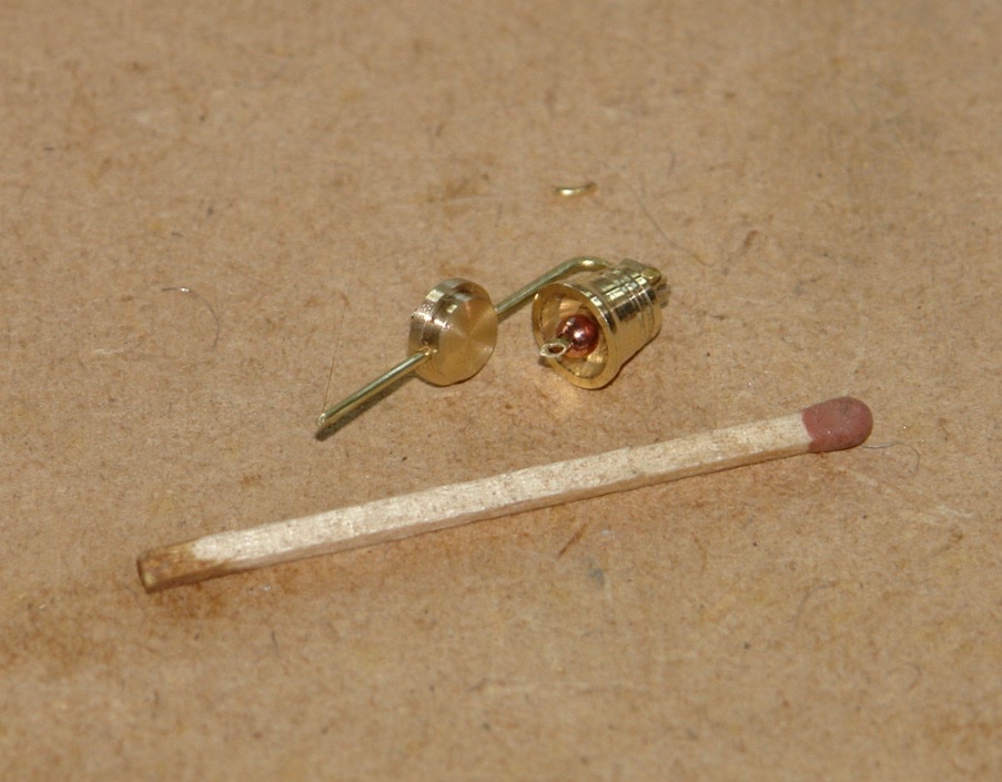
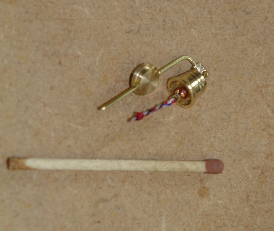
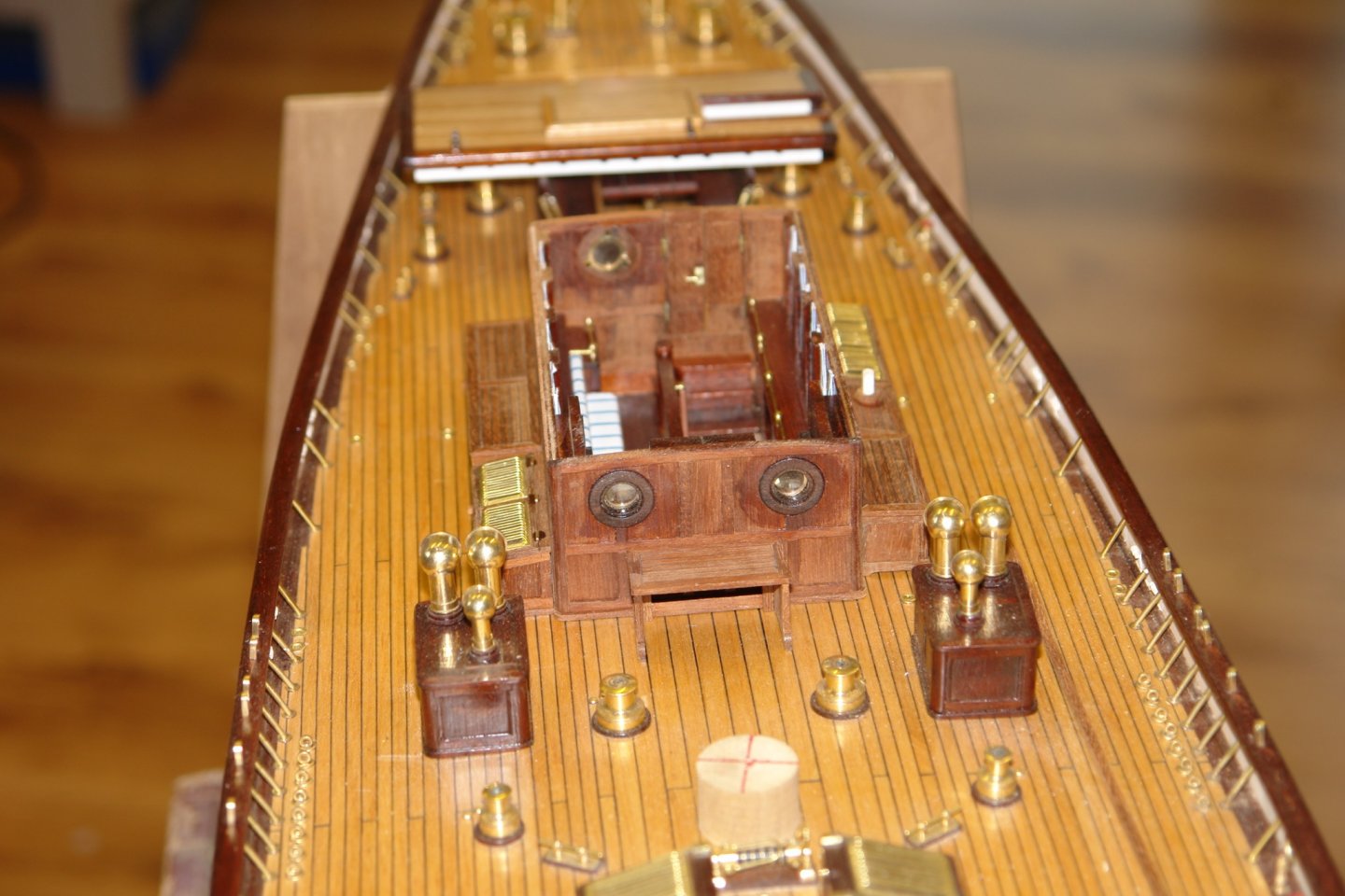
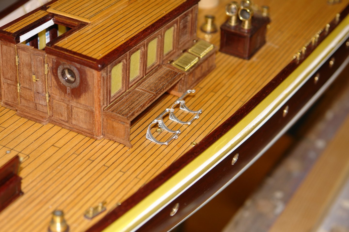
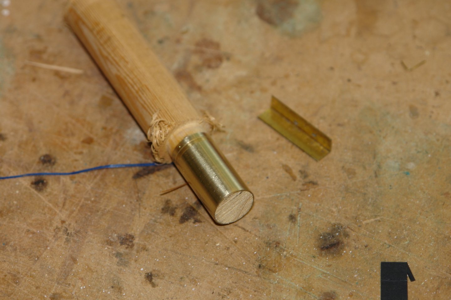
Thank you Michael, I'm sure it would be too distracting from model making. Maybe when I can't see what i am doing anymore. I seem to have been at the deckhouse for an age. It is now nearly complete so I need to get a wiggle on and finish it. Back to the roof - which has 10 small mushroom vents. These were turned and then installed. I also made the rests for the boat hook. The rubbish under the front edge of the hatch is wire wool debris. I then spent a pointless hour making the ceiling lights - totally hidden from all angles of view. The frosted glass is actually nylon rod turned to a dome. I picked a likely looking boathook from the web. I turned the head and drilled a cross hole at an angle to mount the hook. The shaft was then soldered on. The shaft was then covered with brown heat shrink tube and the hook glued in place. Finally the boat hook was glued to the roof. On the front face of the deckhouse is a nice ships bell. Not very big but I couldn't resist giving it a striker. The striker looks large at this magnification but you can hardly see. I platted a bell chord from cotton.


-

-
A very interesting subject Dan. I will be following along. Have a good Thanksgiving.
- 33 replies
-
- 5
-

-
- James B Colgate
- whaleback
- (and 2 more)
-
Eberhard - These particular columns form part of the Pu purification cycle for the Thermal Oxide Reprocerssing Plant, my guess is that it won't feature highly on the decommissioning list for some years. I also did work the Low Active Effluent Treatment Plant, the Solvent Treatment Plant and early cement encapsulation schemes before I went into the more socially acceptable but more lethal brewing industry.
-
Greg, the amount of brass fittings was part of the incentive for making Germania, although the model has more than the original because stainless steel in the original is replaced by brass in the model. In some photos of the original it is clear the crew didn’t always bother with the polish. ) The story of my life Druxey. About 36 years ago I was granted a patent for a liquid distributor for mixing the feeds into solvent extraction columns. It was used in nuclear reprocessing plants, buried deep inside highly radioactive equipment behind 6 feet of concrete, not to be seen again for a thousand years. Allan, I used soft solder. I find silver soldering Is too aggressive when used on very thin brass. Soft solder is generally strong enough if you keep the tools sharp and the cuts light. John, Pat, Bruce, thank you for your supportive comments.
-
Cap San Diego by mikegr - 1/160
KeithAug replied to mikegr's topic in - Build logs for subjects built 1901 - Present Day
Loverly looking ship - from an era when naval architects still thought aesthetics were important. Good luck with the build -
Another little masterpiece Javier. You must let us all see the fleet assembled together some time.
- 15 replies
-
- 3
-
-
- fishing boat
- small boat
- (and 1 more)
-
Frames looking good and i particularly like the Fanta support jig.
-
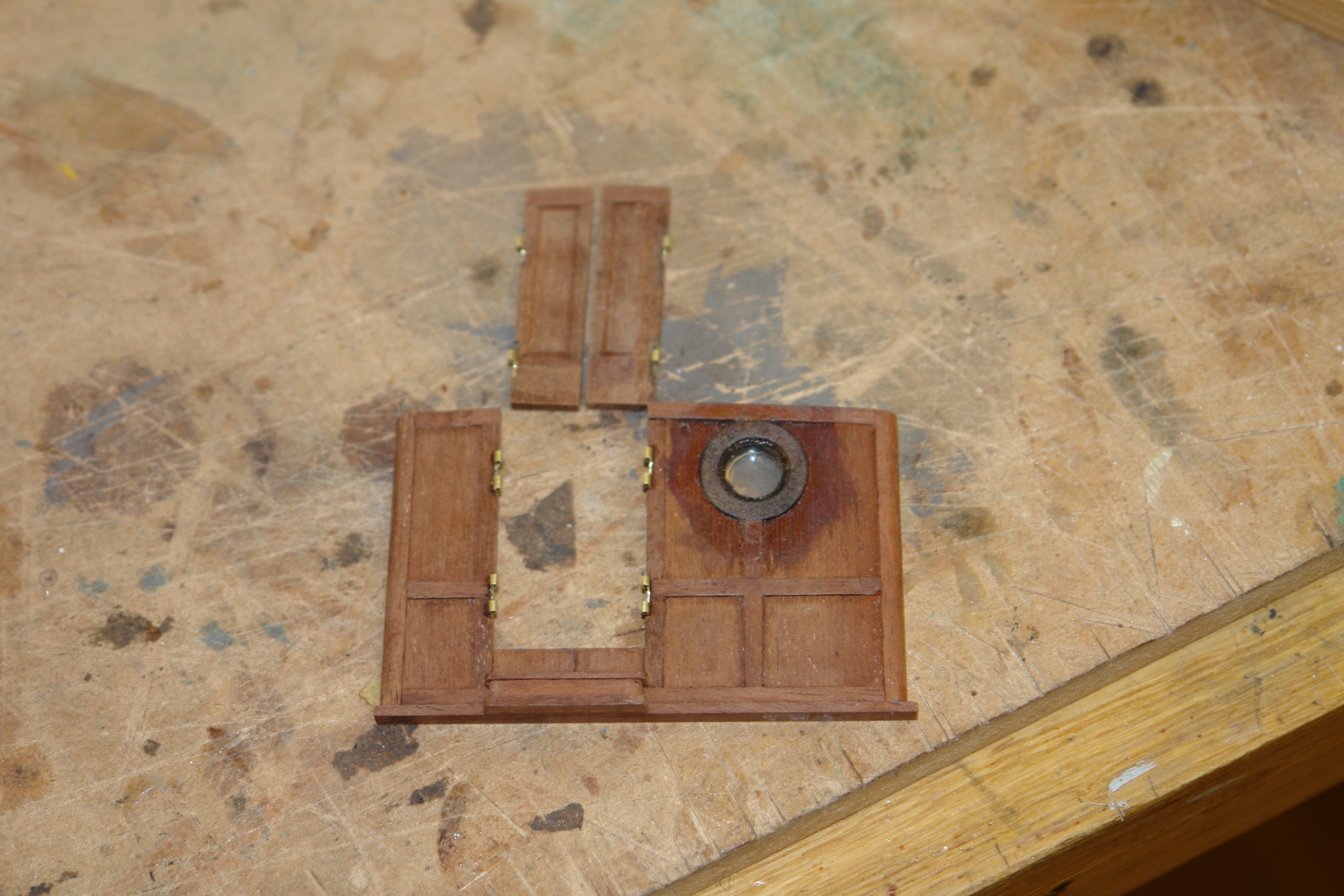
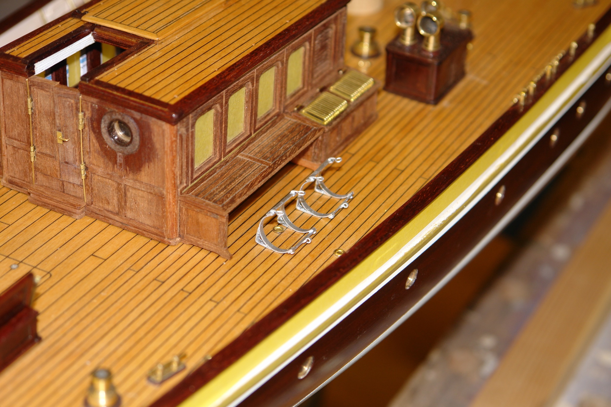
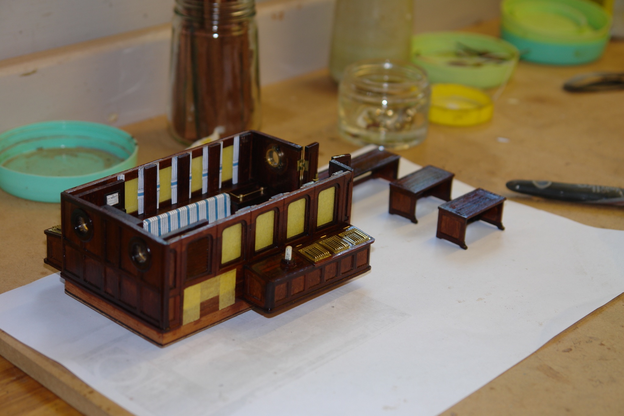
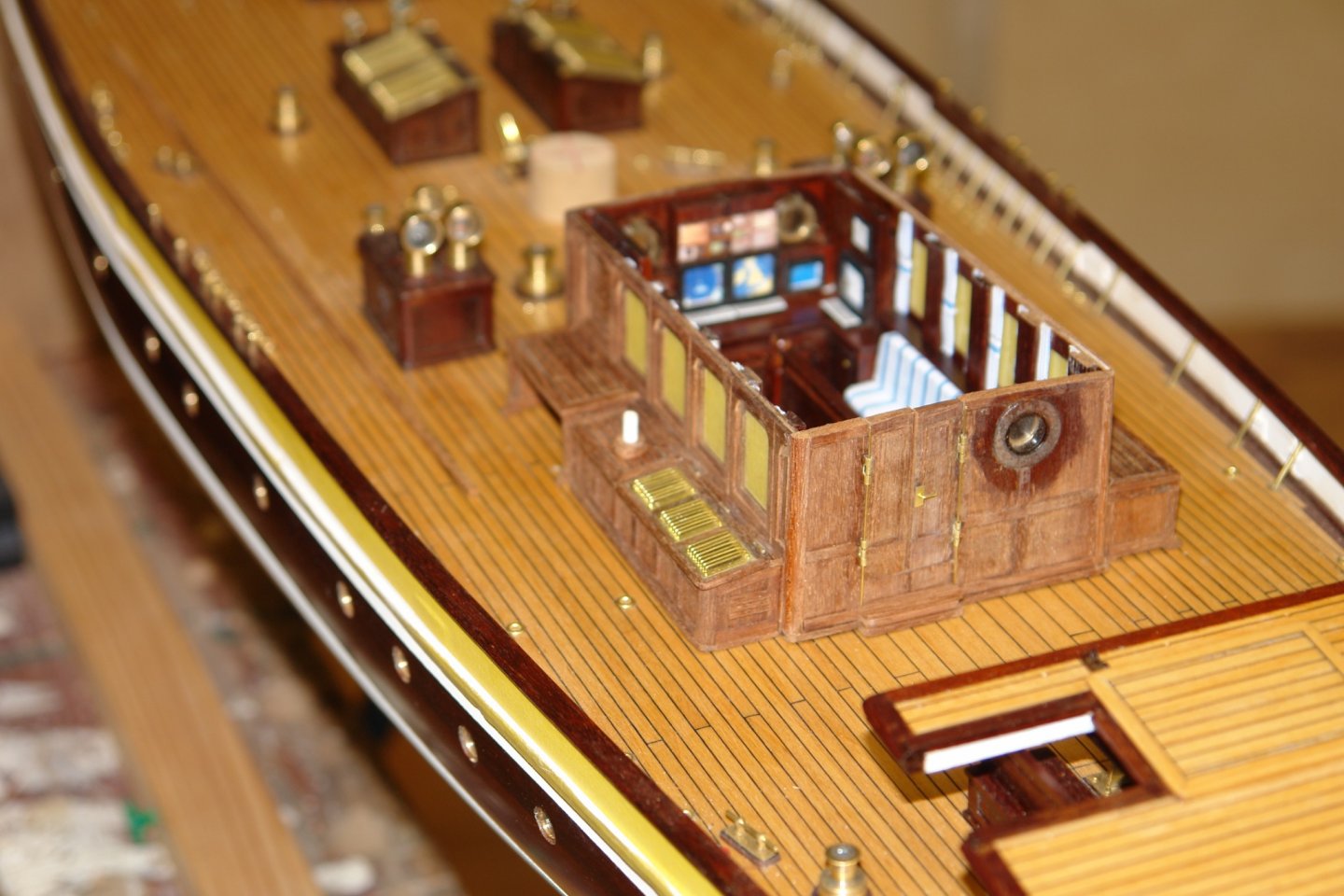
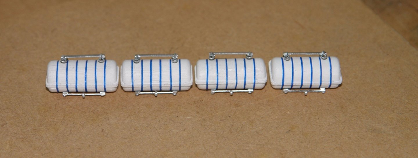
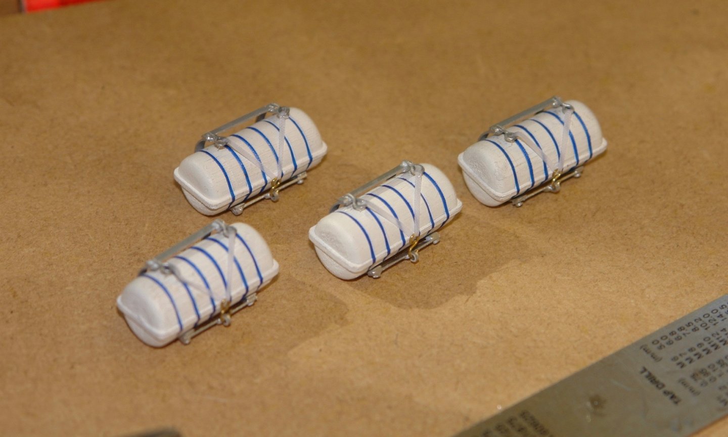
Thank you Steve, Gerrt and Allan. I do think finding a way of doing something is the most fun part of the hobby. Also Thanks to everyone who has left a "like". I am feeling that my work is a bit unstructured at the moment as I dot about finishing parts of the deckhouse. Sorry! I thought the time had come to finish the back walL I cut out the rebates for the door hinges and glued them in place. The tricky bit was ensuring the correct alignment of the 2 parts of each hinge I made the door plates for the door handles and bent a piece of wire to form the handle. The wall was then glued in place. The door hinge pins are temporarily replaced by a couple of thin wires. I have also drilled the port wing bench and inserted a dowel (white) to take yet another cowl vent. I then painted the raft cradles silver and placed them on the deck besides their covering bench. I test fitted the roof and did a bit of light sanding adjustment to make it fit. The roof and bench are not yet glued on. I then took the various beck house components off the hull, masked off the unpainted areas and started the process of painting the parts with Poly. While drying I went back to the rafts. They were given 3 coats of white paint before case straps were added, Made form ripstop tape cut .010" wide with a sharp craft knife. I then cut the cradle retaining straps and mounted them (a bit translucent and hence difficult to see). I was eager to see what they looked like under the benches.


-
Tom . I'd stick with the plan of not drilling through the outer layers if i were you. Because the dowel grain runs in a different direction it is likely to contract at a different late over time and hence become visible. One trick to stop differential movement between layers is to sprinkle a little salt on the glued surface before clamping. The angular grains stop the movement, (although I think your doweling plan is better).
-
Everyone has to start somewhere Tom. It is probably a good idea to start with something relatively straightforward. You can always progress to HMS Victory in the new year.
-
A lovely way to finish this build, it is a pleasure to follow along.
- 158 replies
-
- 2
-
-

-
- byblos ship
- Egyptian
- (and 1 more)
-
What do I want for Christmas
KeithAug replied to Worldway's topic in Modeling tools and Workshop Equipment
Seconded -
An interesting and unusual model. I will be please to see more.
-
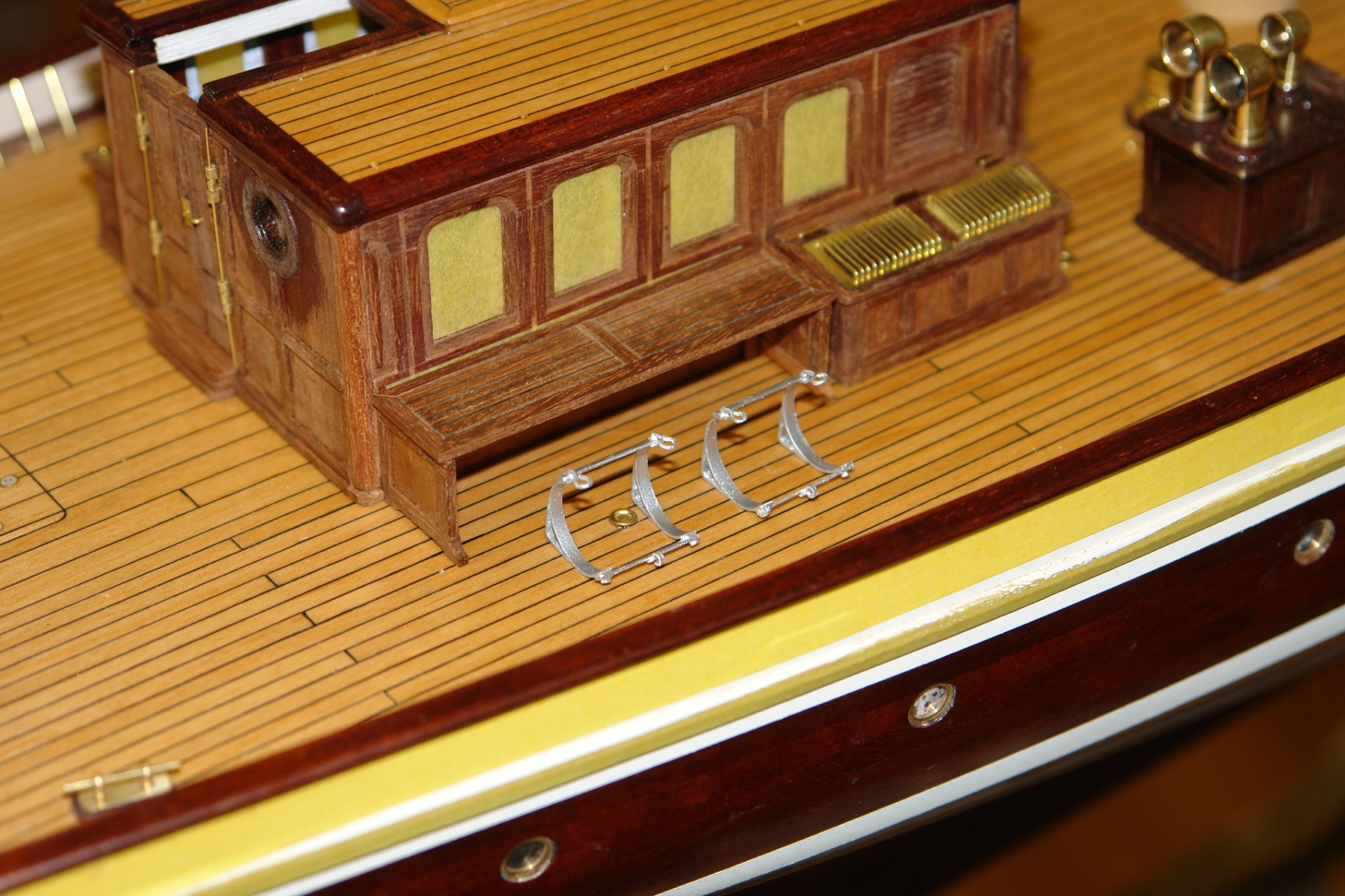
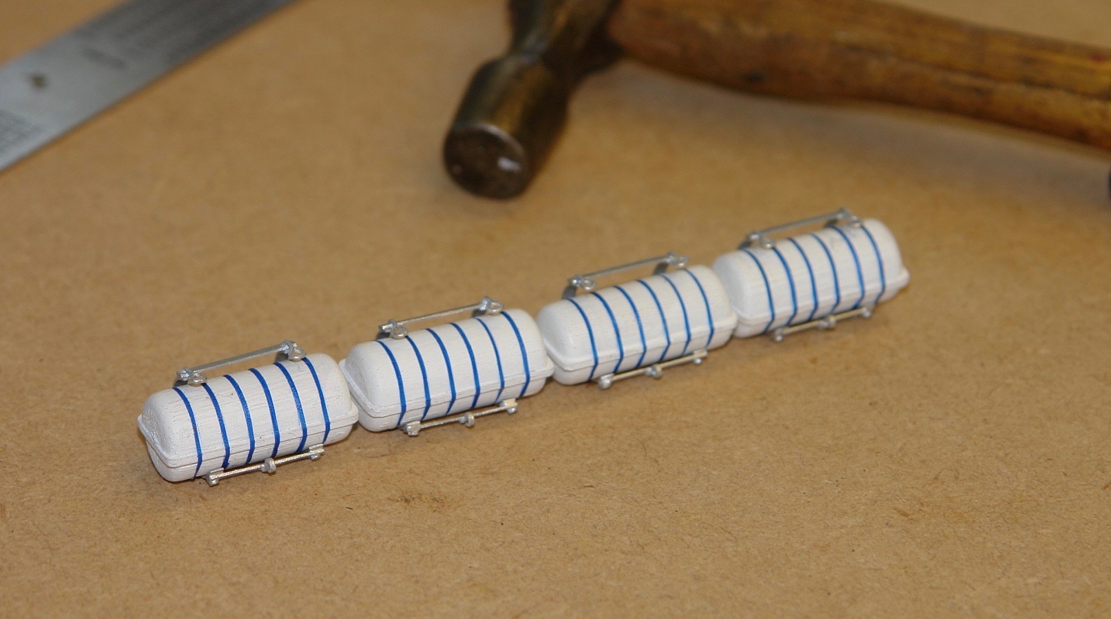
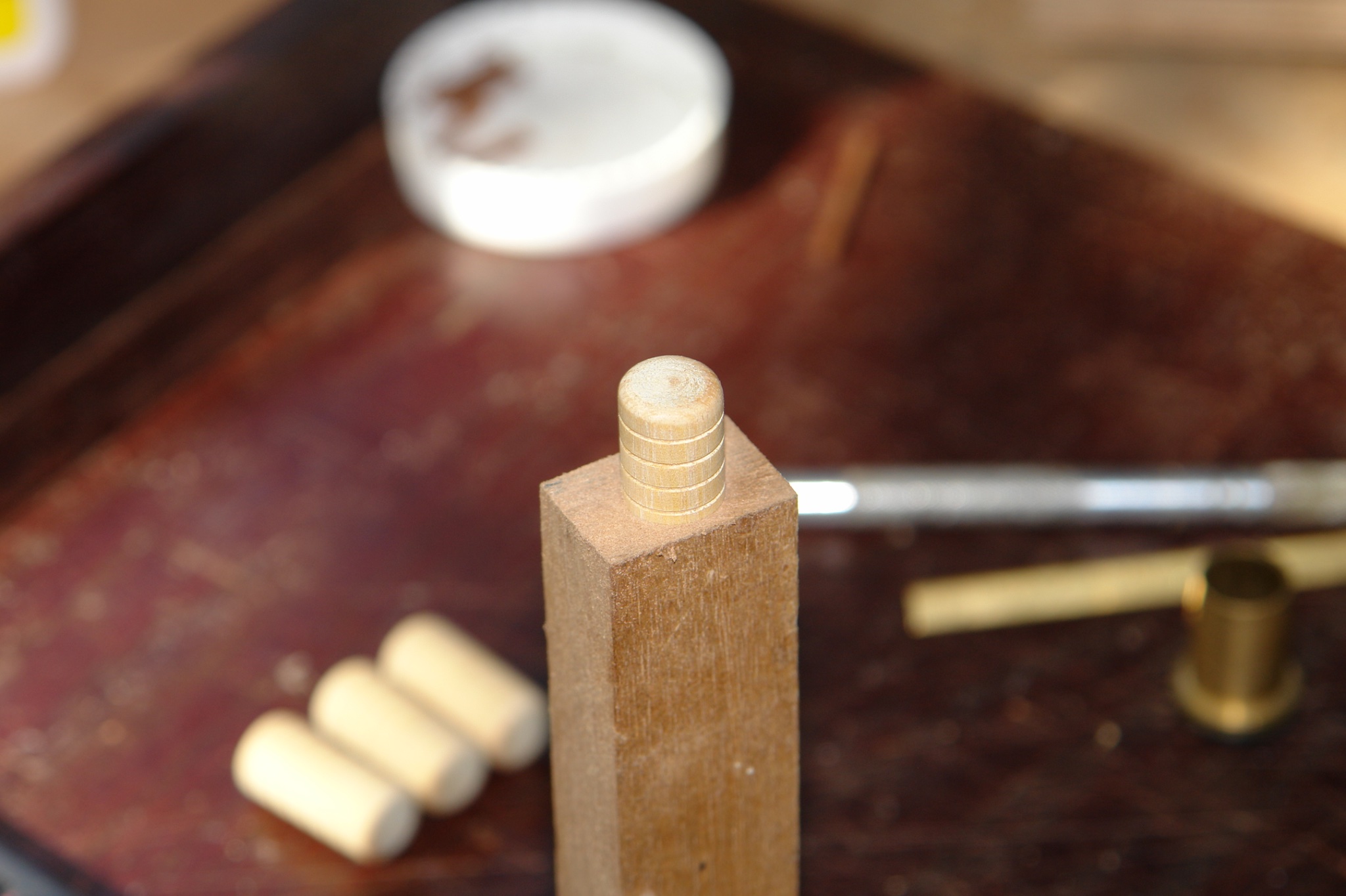
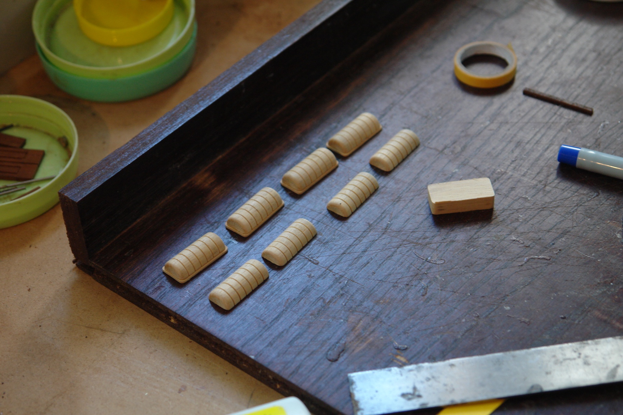
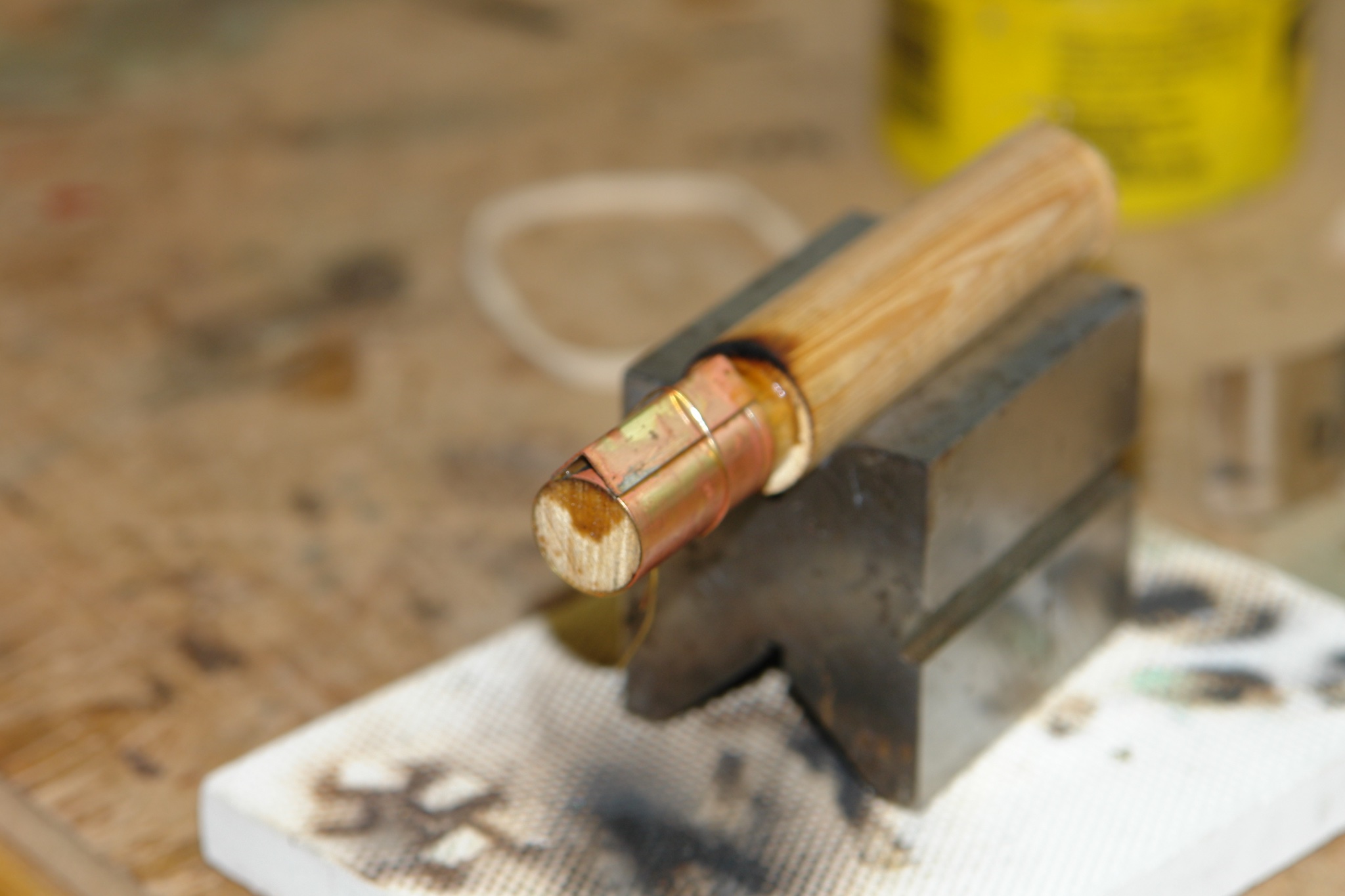
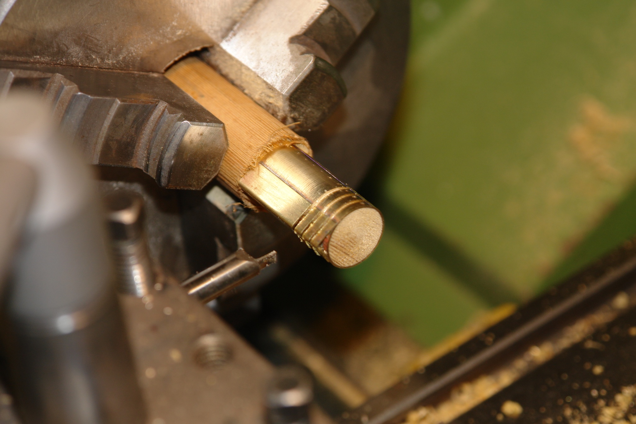
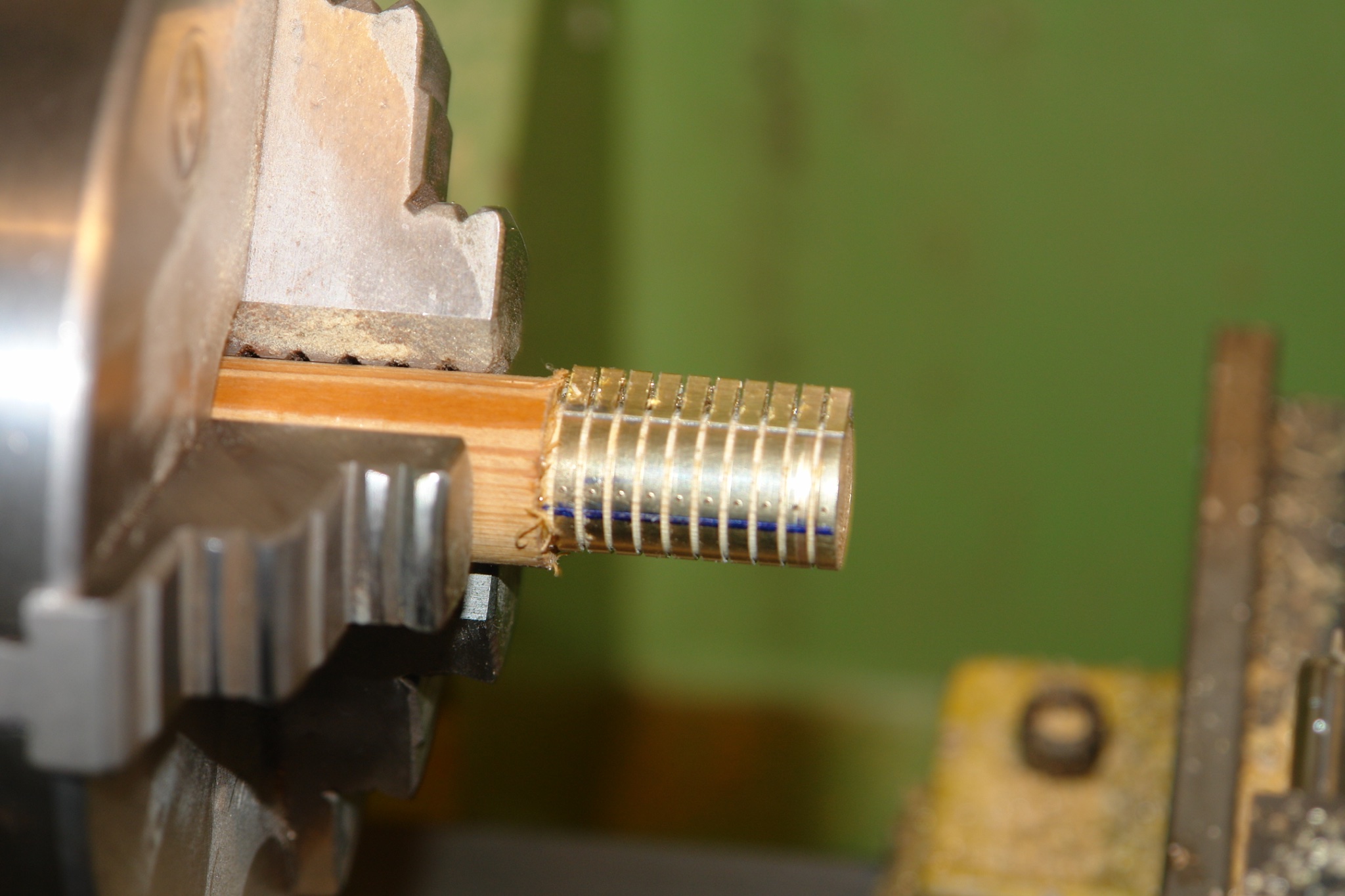
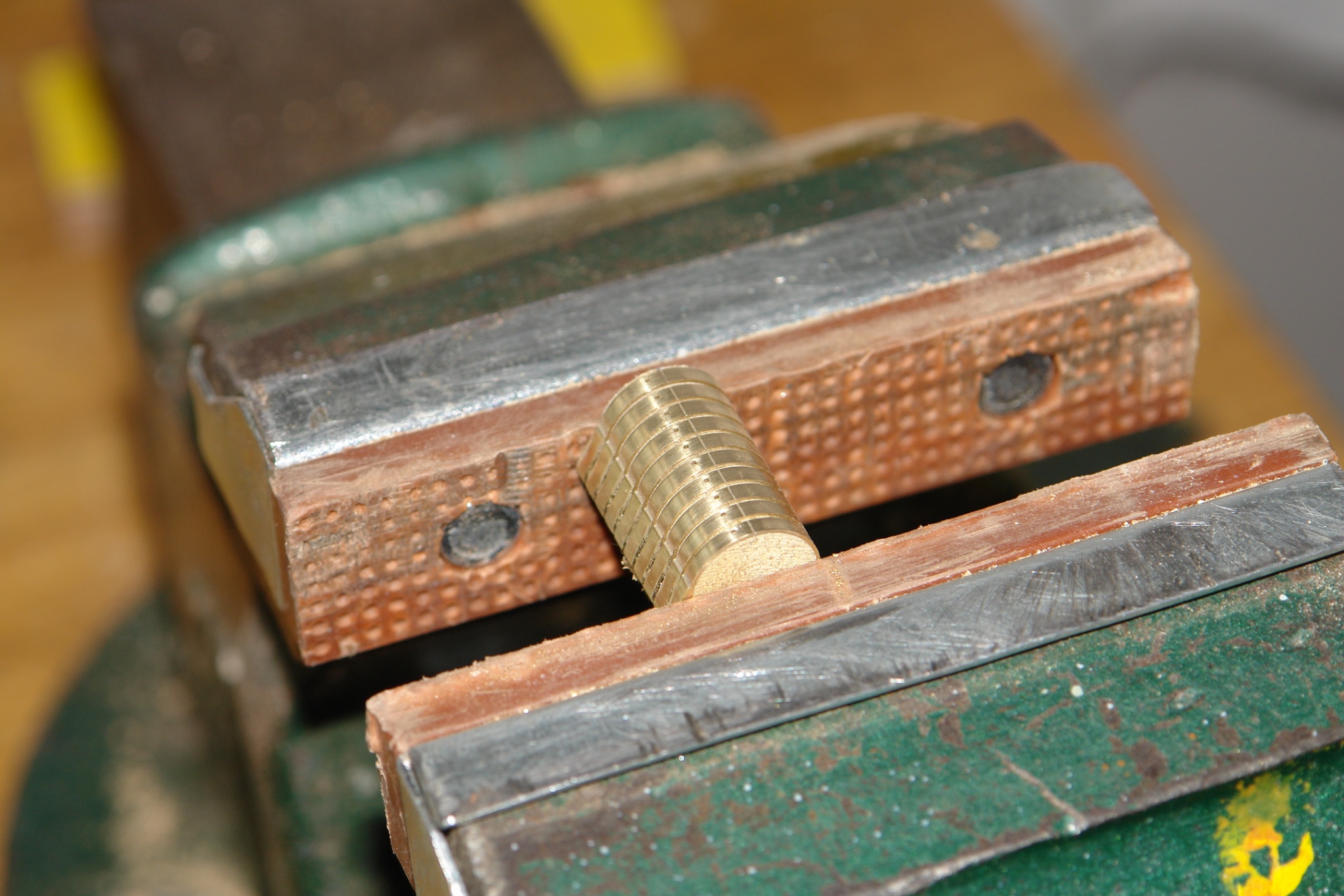
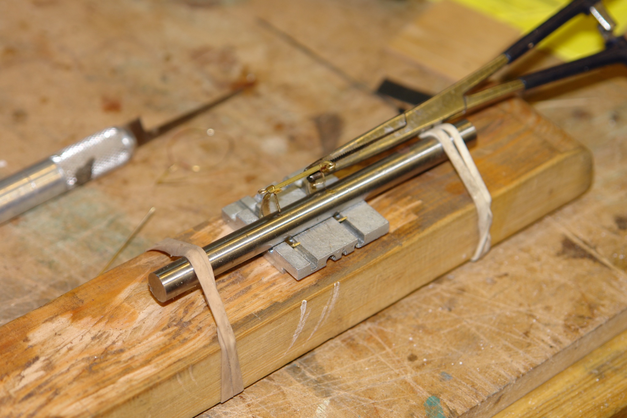
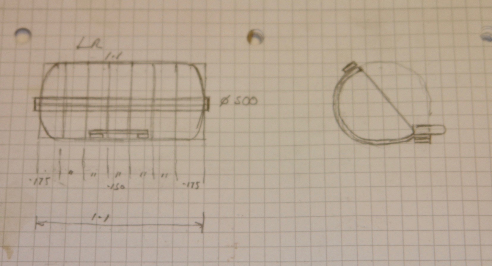
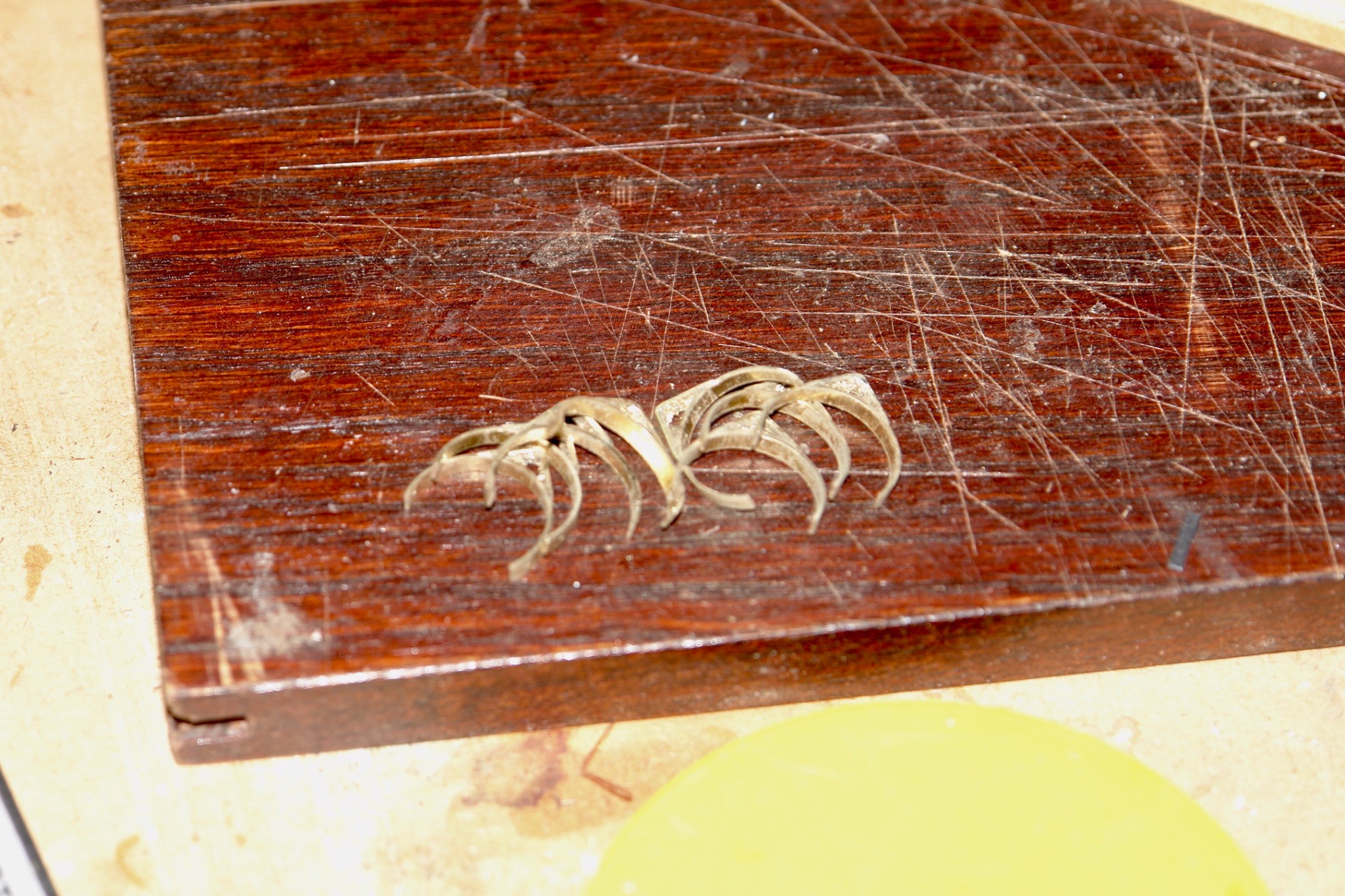
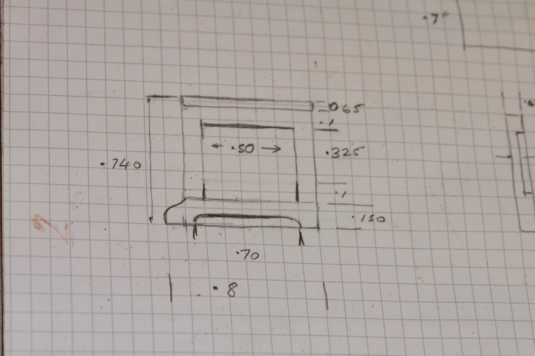
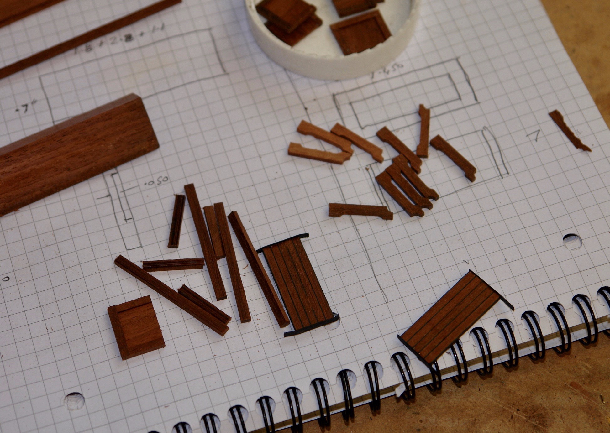
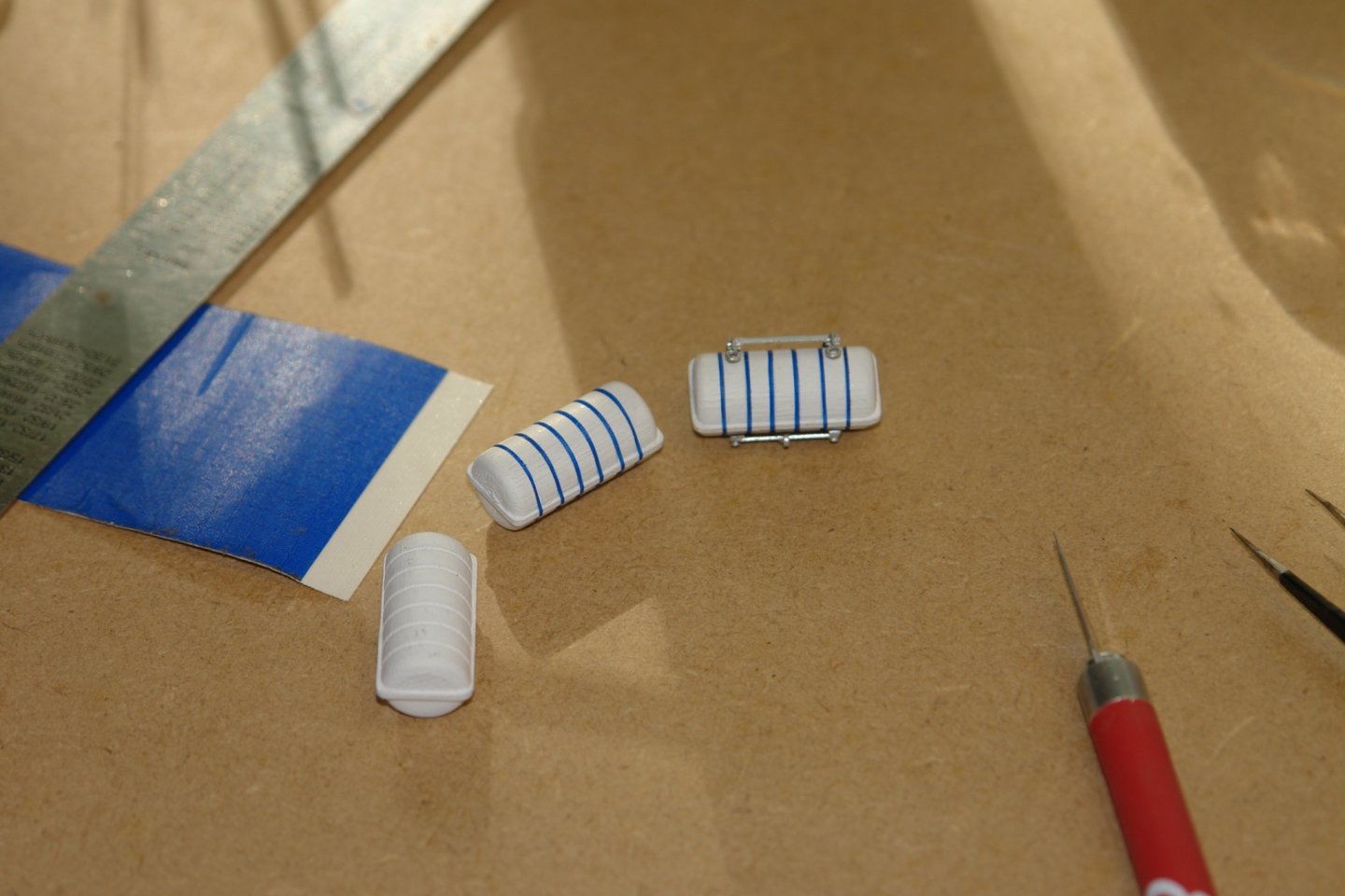
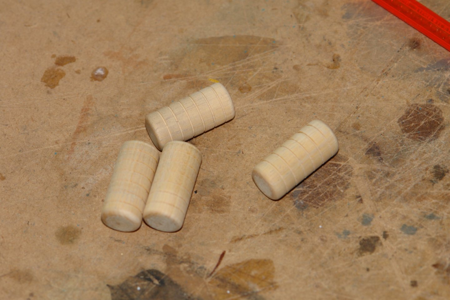
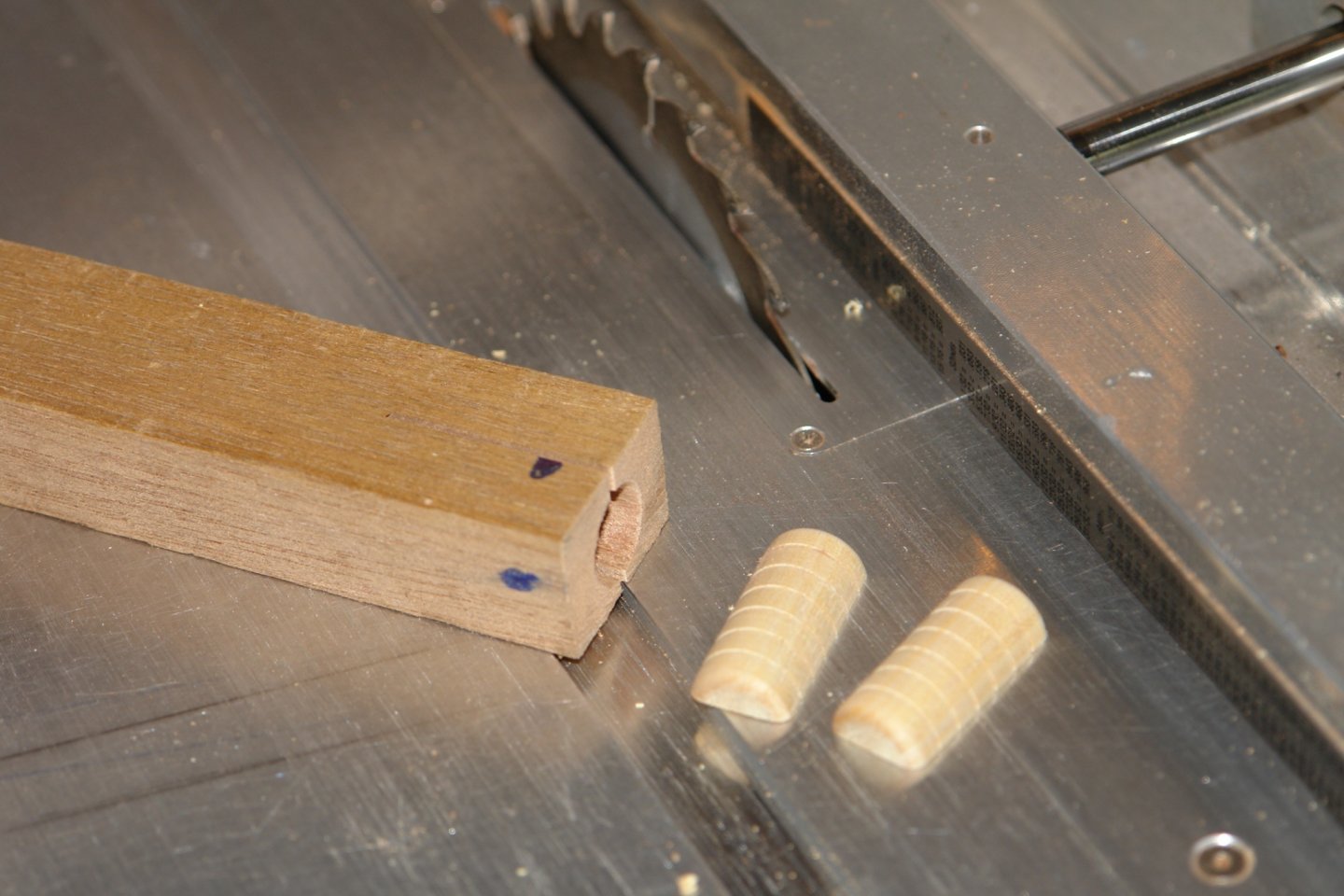
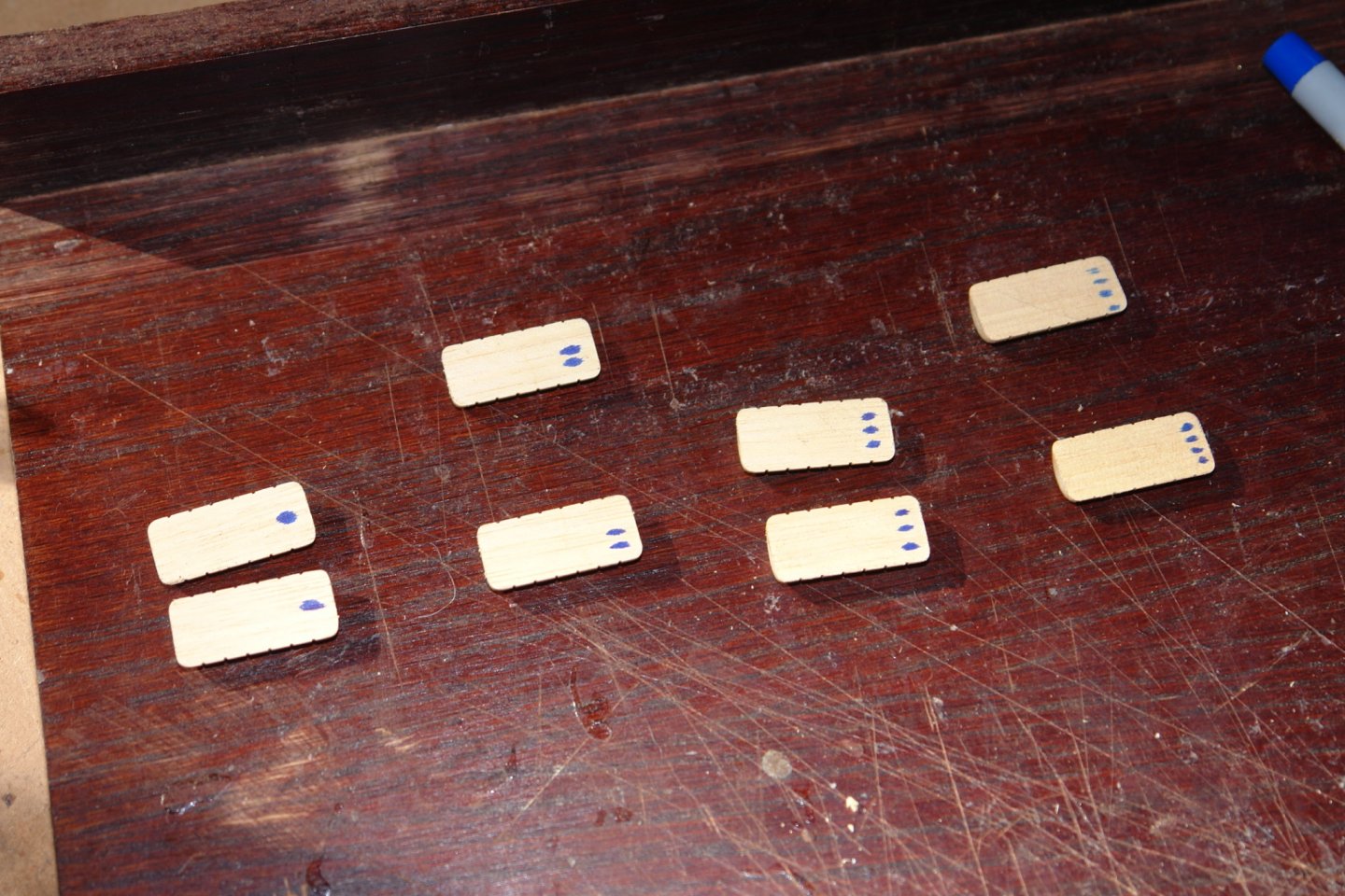
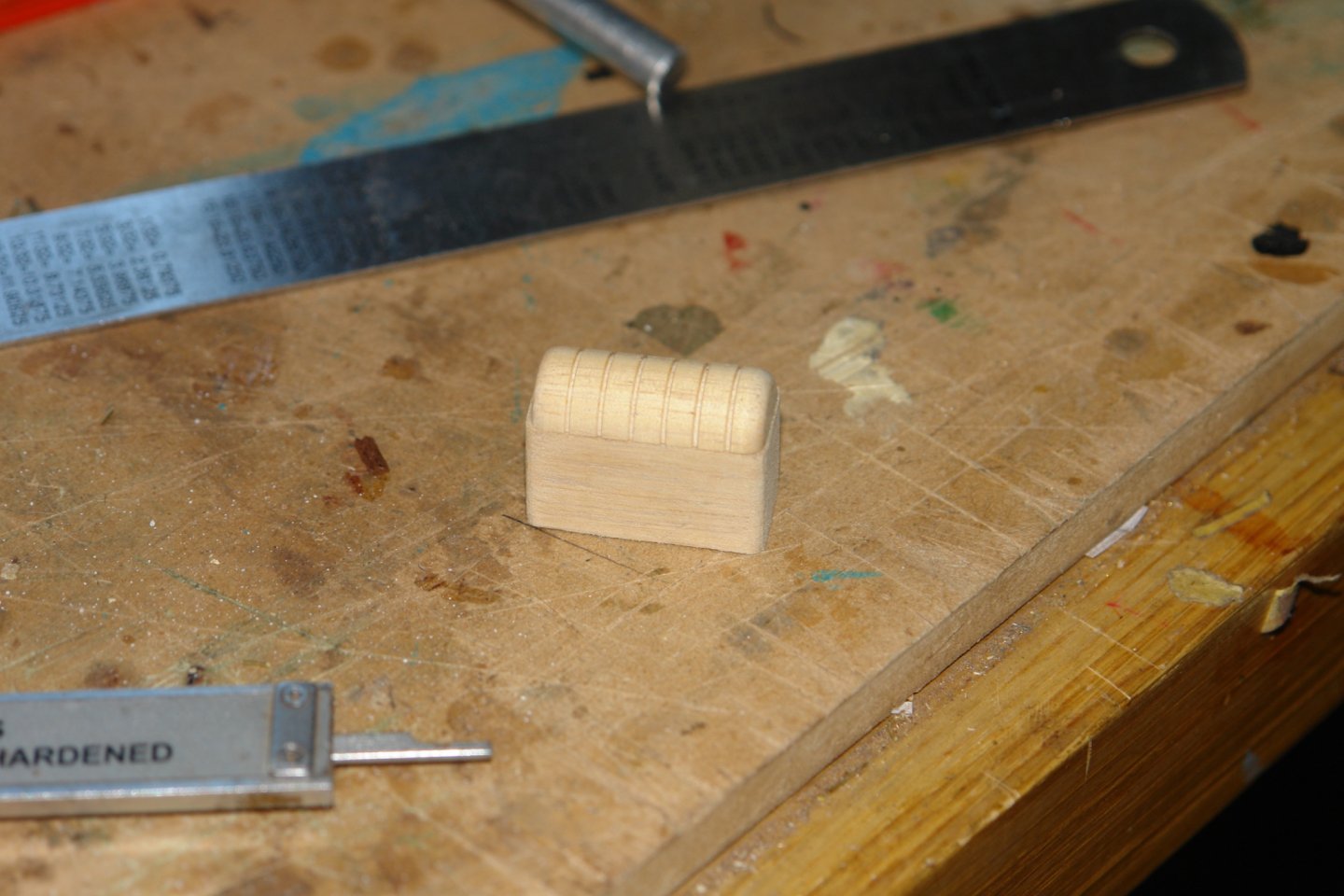
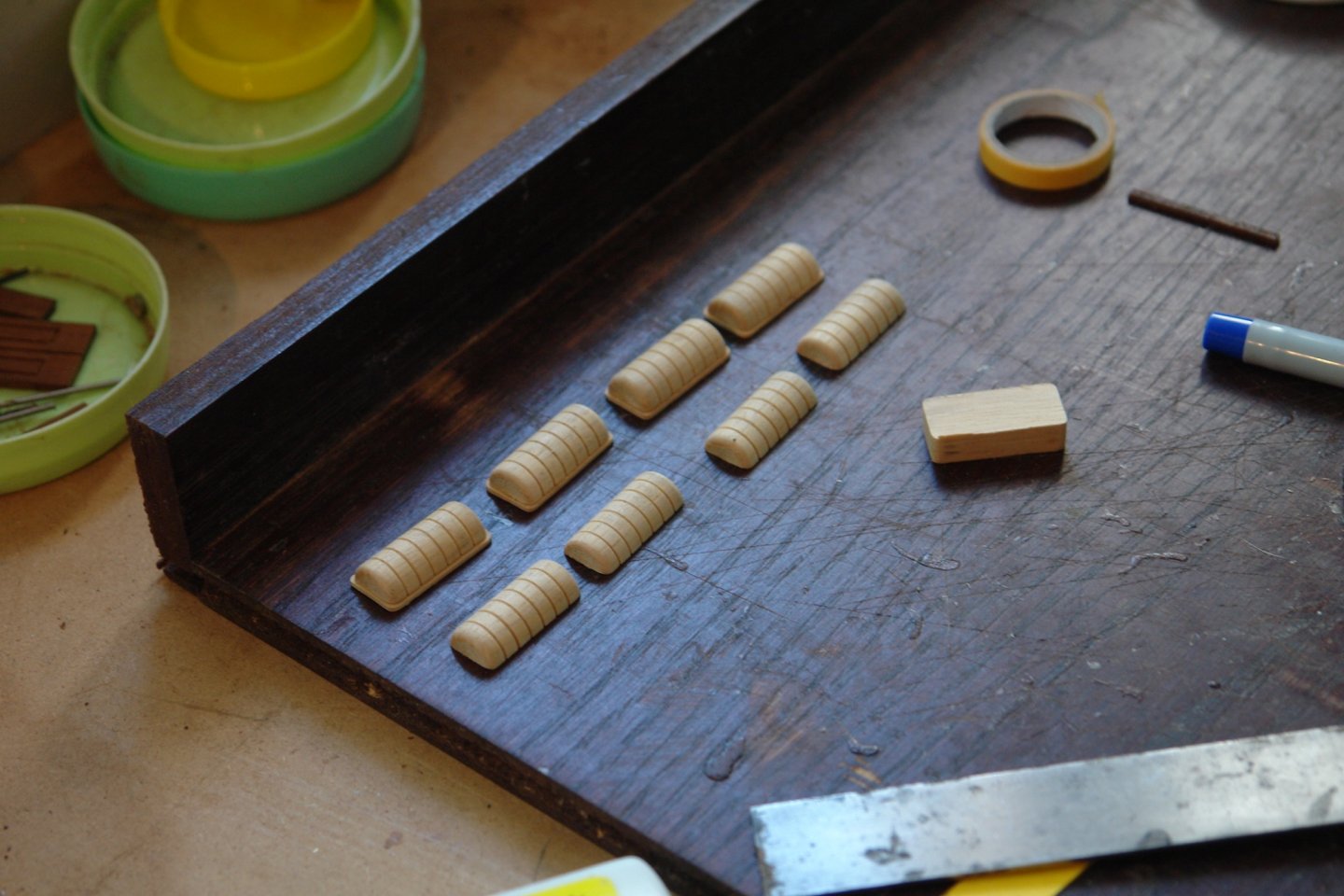
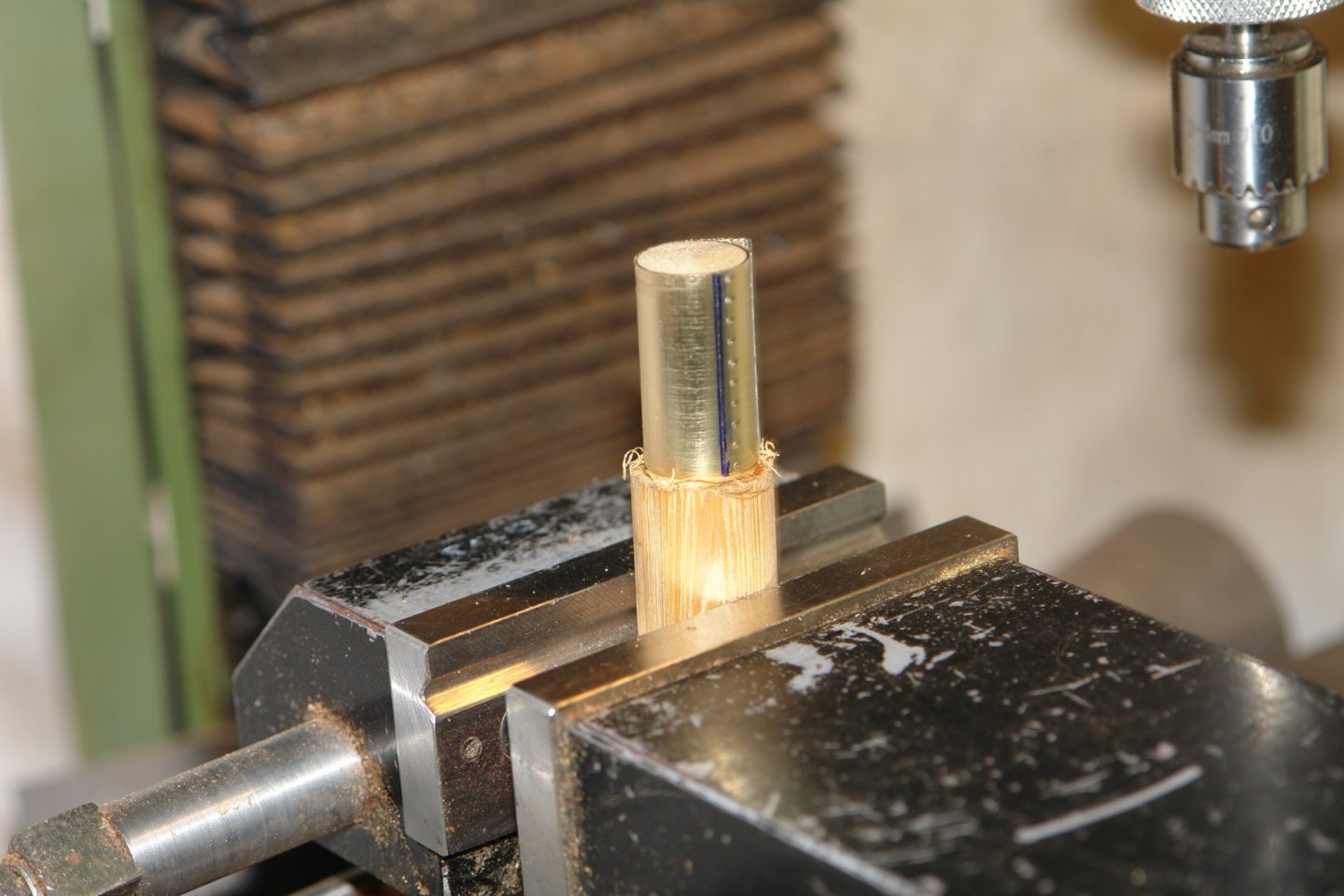
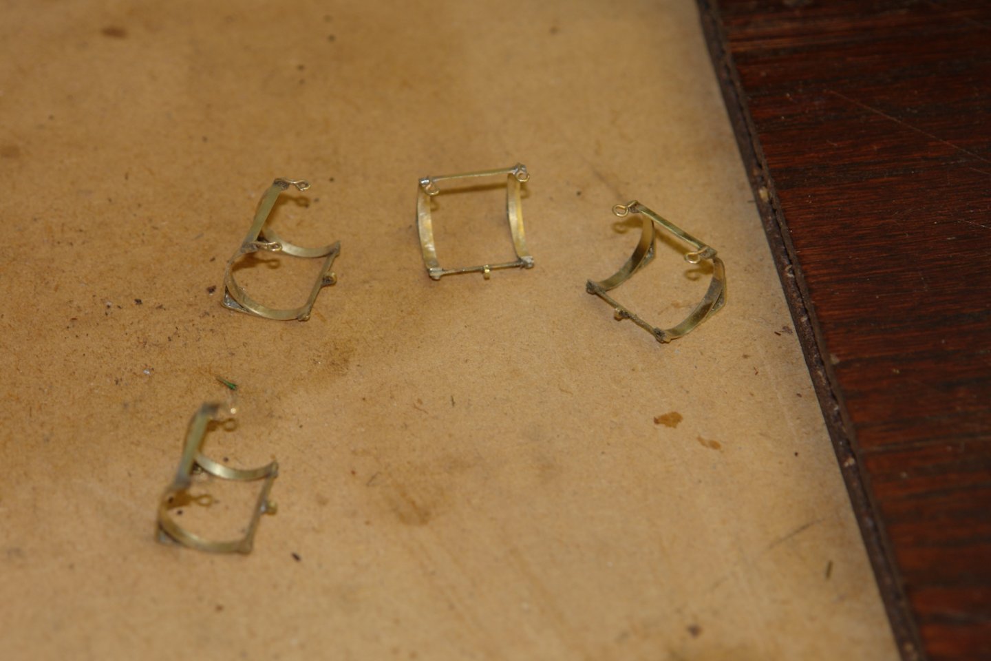
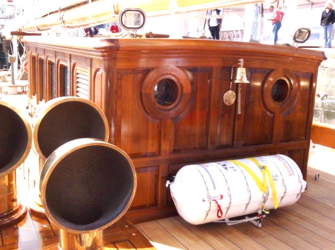
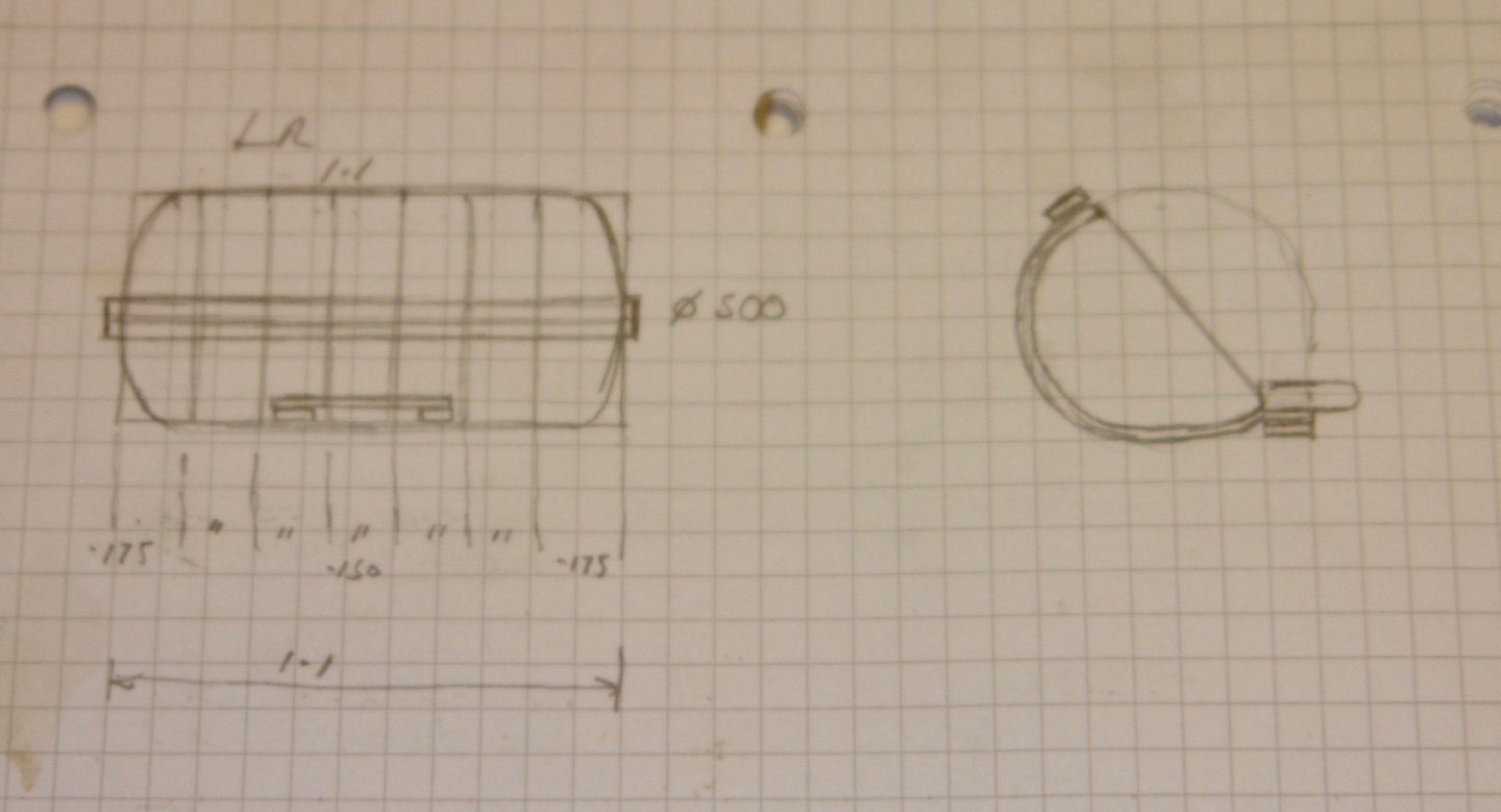
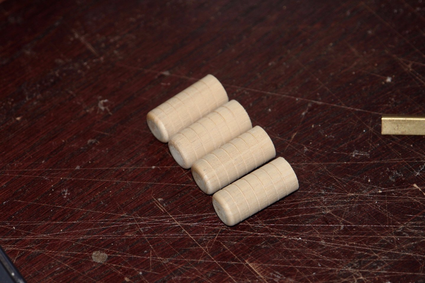
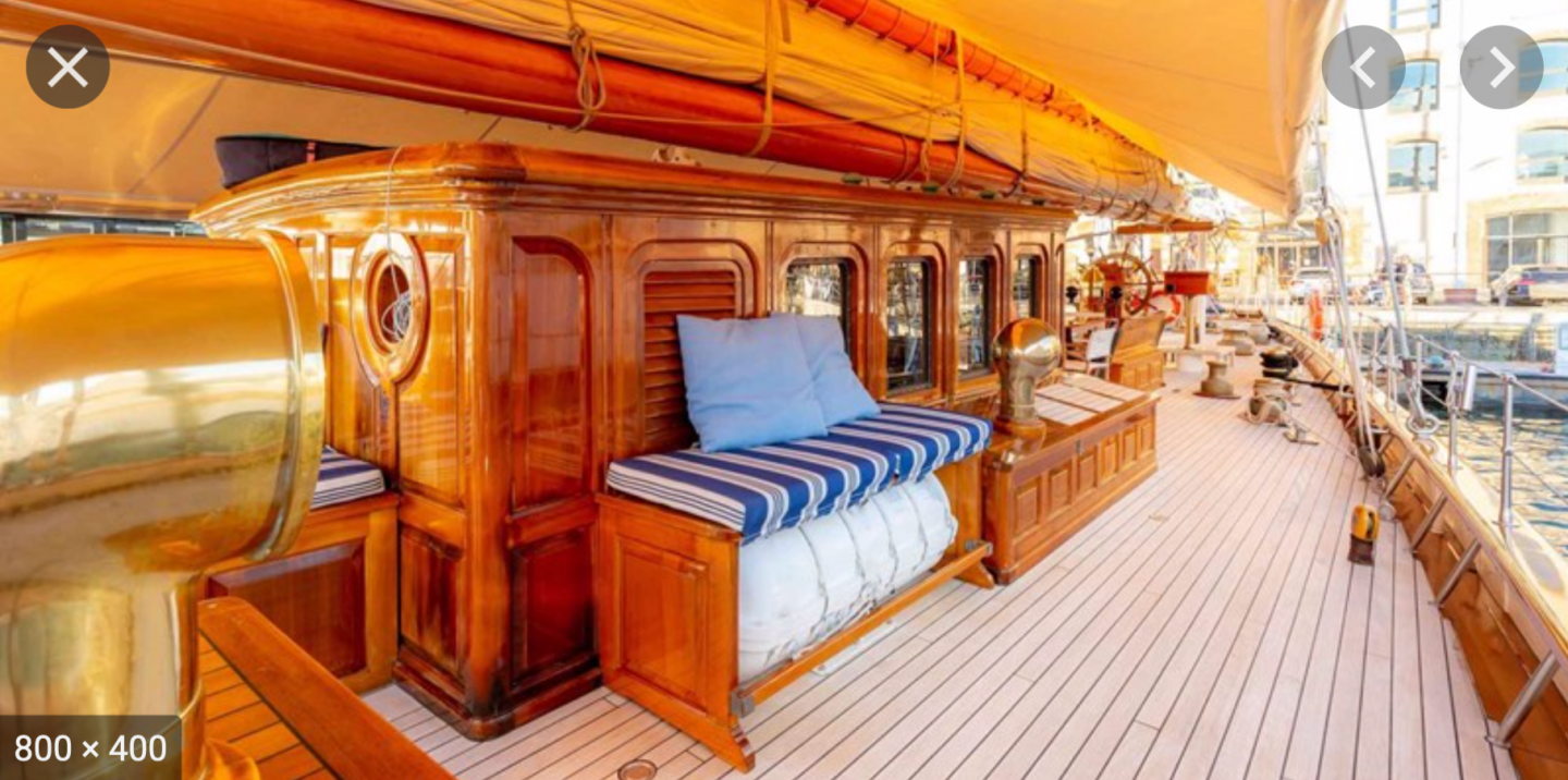
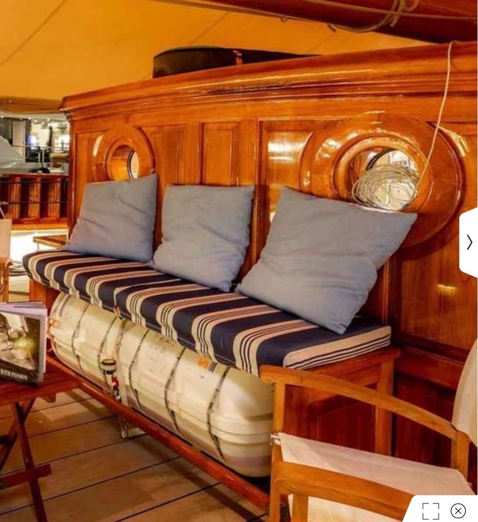
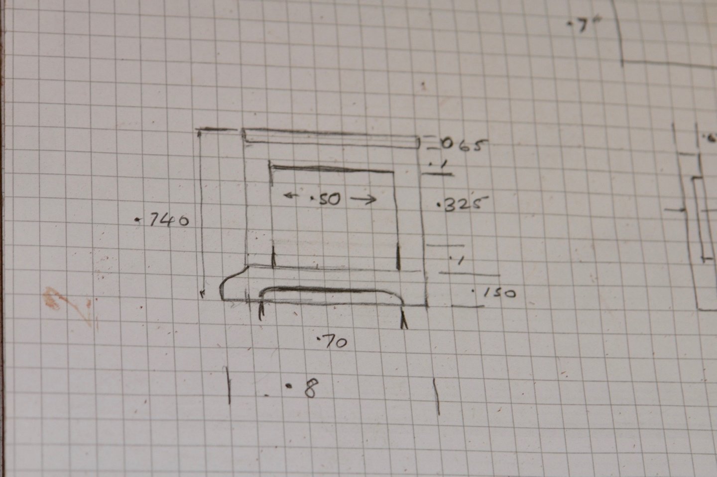
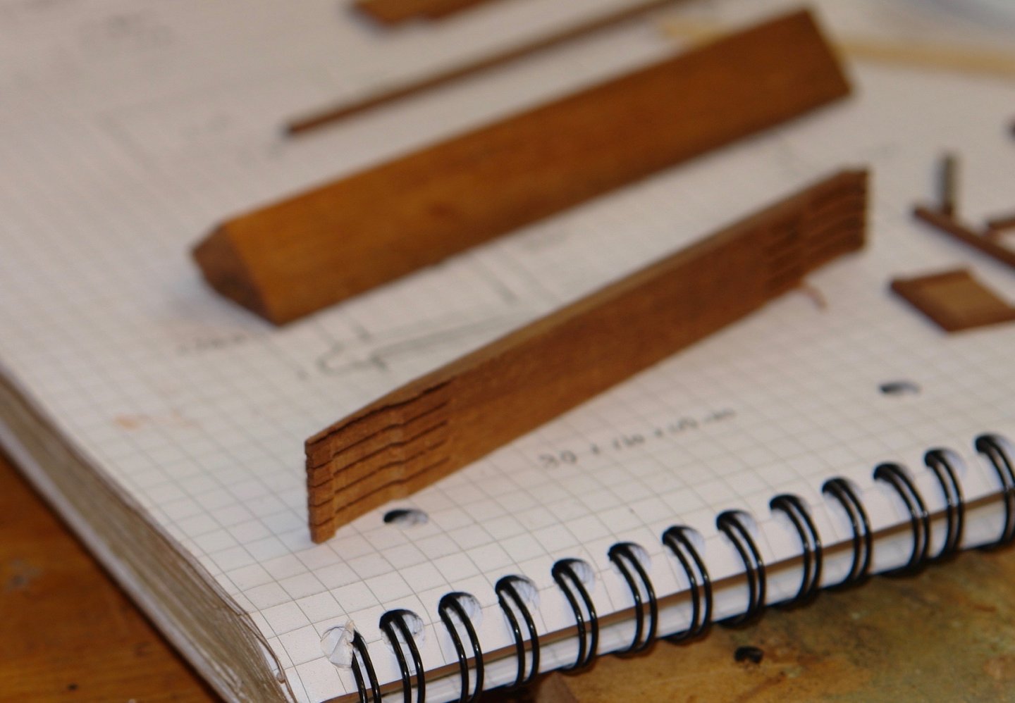
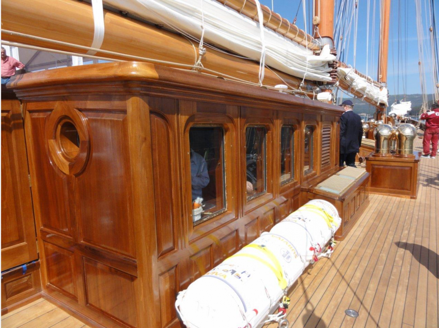
I have made a start on the life rafts - 4 in total. I had a fairly decent photo to work from. The cradle in which they sit isn't very well defined but as it won't be very visible when installed under the benches I don't think this is too much of a problem. I did a rough sketch of the life raft and cradle. The rafts are 0.5" diameter by 1.1" long. Most of my wood stock is recycled from one source or another so its suitability is generally a bit problematic. I chose a piece of dowel and turned the life rafts, including the strap grooves. The wood turned very nicely producing crisp edges on the grooves. Once turned the rafts were parted off turned round and finished. The left over wood was placed in my good tiber pile. I then needed to accurately cut them in half to reproduce the opening flange. I drilled a hole in the end of a piece of scrap wood to form a holding jig. I then pressed the raft into this before cutting down the centreline on the table saw. I used a TCT blade with a .055" kerf as this was right for the .055" thick flange. I kept the halves in matched pairs although this wasn't really necessary. I then machined and sanded a block from which to form the flange. I then slit off .055" wide flanges before starting assembly. I then diverted on to the cradles (fabricated from brass). The circular segments of the cradle started life as a tube which was turned down to give the required wall thickness .020". The turning was done over a wooden spigot . I also bent up a bit of sheet to form the cradle base. The two parts were then soldered together. 2 parallel rows of .025" diameter holes were then drilled to take eyes for the raft retaining straps. Then the straps were parted off (.080") wide using a .020" wide parting tool. I made 10 although I only needed 8. A segment was then cut out with the jewellers saw to form the opening. You can just about see the scribed cut line in the next photo. I made a crude jig to hold the parts for soldering on the connecting straps. Slots in the aluminium guarantee the correct spacing and the steel bar and elastic bands provide the clamping. The connecting straps are .015" thick and .080' wide. The eyes for attaching the straps were also soldered on at this stage. The cradles were then cleaned ready for painting.


-
Sooty, very nice small model. The sea is very realistic. It would be good to know how you did it.
-
Good progress Allan, the furling gear looks particularly realistic. Allan, for future reference this company produces micro-bore brass tubing that is good for sleeves. It’s a bit expensive but you don’t use much. https://www.albionalloys.com/en/ https://www.chronos.ltd.uk/omega-search/?q=Albion alloys .
-
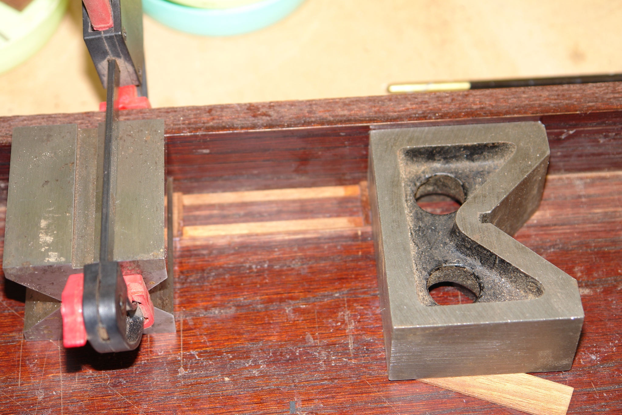
Eberhard, I have to agree and even worse without the benches in place. At least they will add a bit of diversity to the build process. Allan, I tend to buy things like this second hand from a local dealer. V blocks are handy but 1,2,3 blocks are probably more useful for this application (and a bit cheaper). see - https://www.arceurotrade.co.uk/Catalogue/Workholding/Vee-Blocks-Angle-Plates/Stevensons-Metric-Blocks. However if I hadn't had the V blocks handy I would have used lego or duplo blocks as they are accurate and cheap.
-
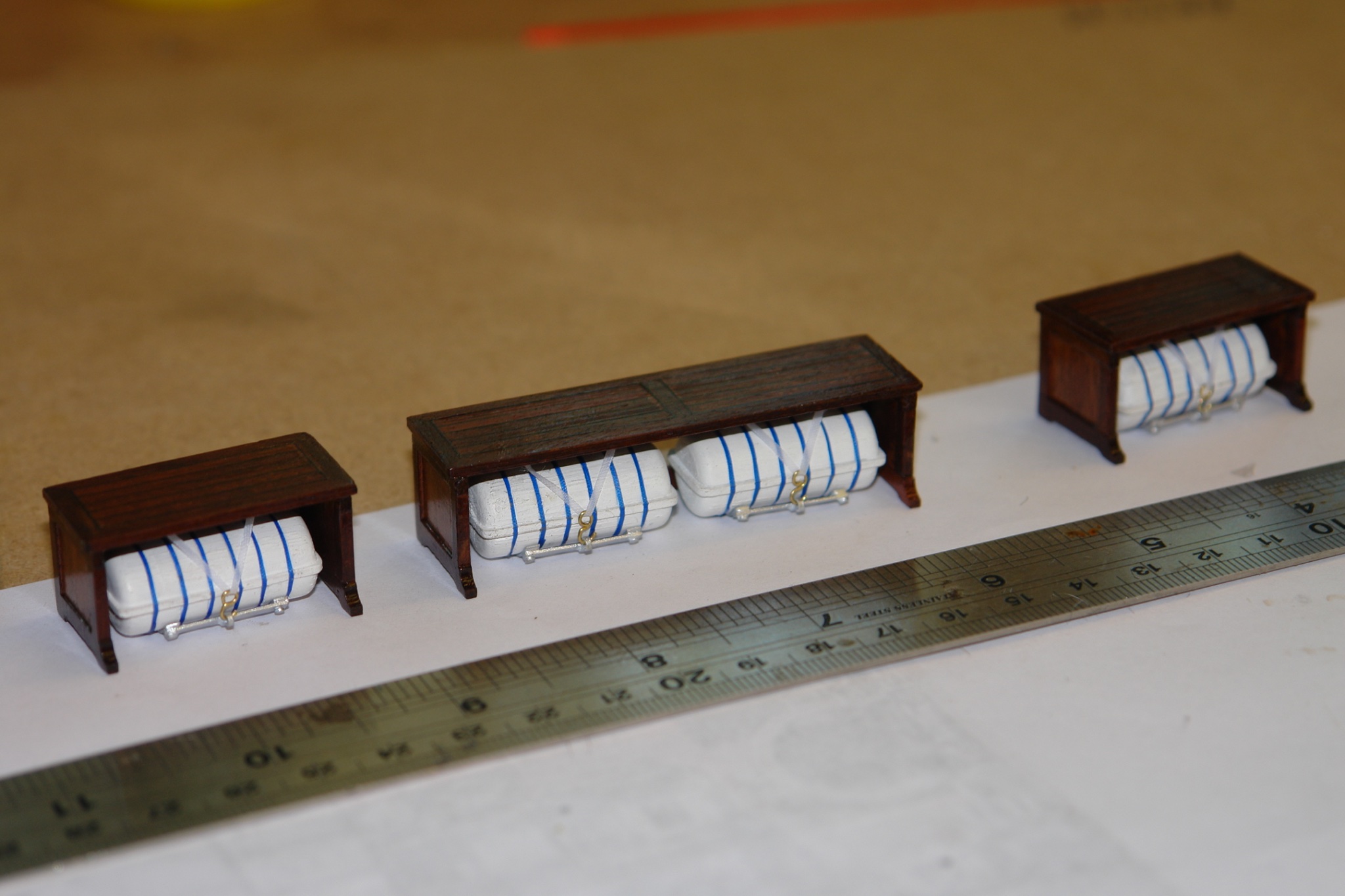
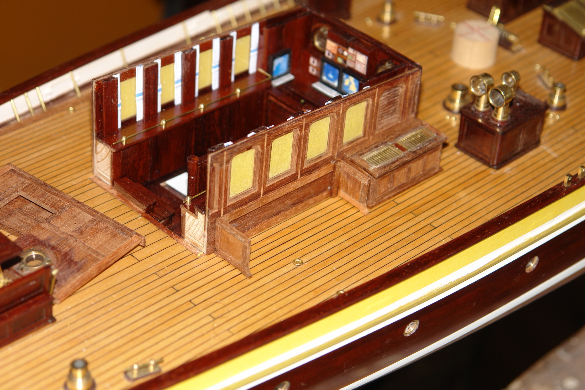
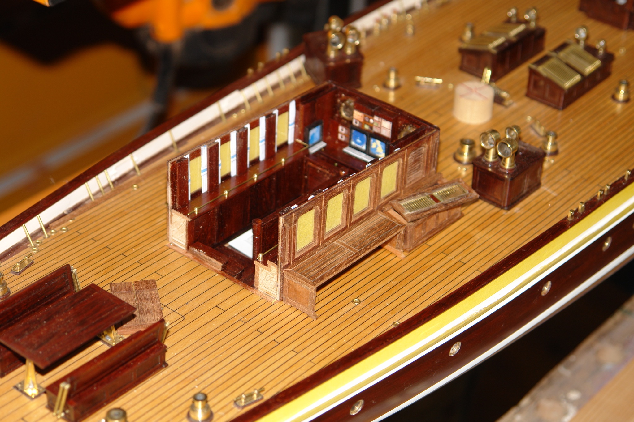
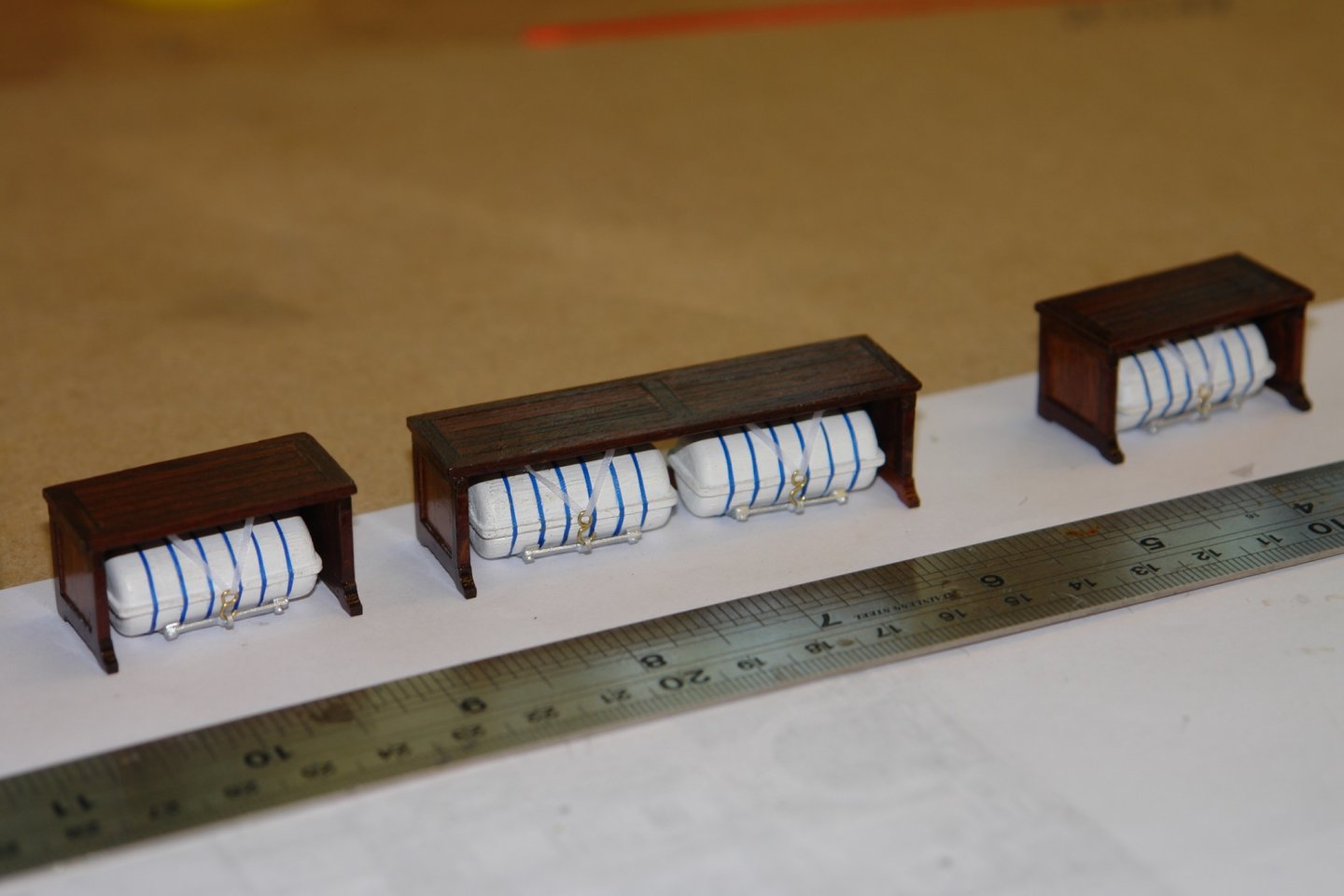
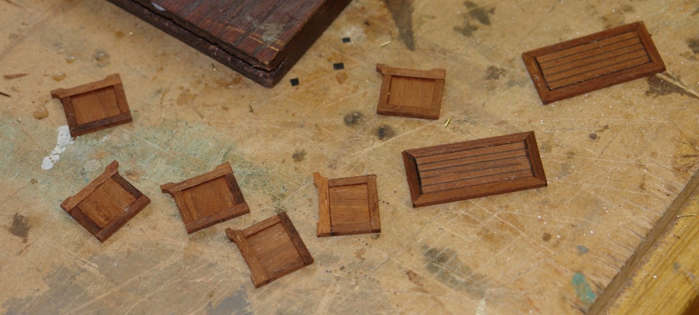
Keith, Eberhard, John, Richard, Boris, Kees, Pat, thank you all for your kind comments. Moving on, I next attempted the benches that sit over the life rafts. These benches disassemble and are variously shown in position or removed. I will build the model with all 3 benches in place, I won't reproduce the cushions as the photographs only show these when the boat is at anchor or moored. As usual I started with a sketch, scaled from the photographs. all 3 benches are of different lengths and I only needed to sketch the ends. The only slightly complicated elements were the feet. These were profiled on the mill before being slit off. All the other bits were cut out and the planked bench tops were made. I glued the ends to joining planks using a couple of engineers blocks to keep things square. Finally the tops were glued in place. I now need to make the life rafts but that will be another day.


-
Eberhard, I was not aware of this type of anchor although in concept it seems similar to what I would call a Danforth anchor. The stern anchor is what I have always called a Fisherman’s anchor. Both very nicely made given the limitations of scale. Taper turning 0.3mm steel rod is a bit of an achievement. Was it a case of very light cuts or did you conjure up some other technique?
-
Brian, isn't it annoying when life intrudes. Great job on the stove, I particularly liked the aluminium tape technique.