KeithAug
-
Posts
3,986 -
Joined
-
Last visited
Content Type
Profiles
Forums
Gallery
Events
Everything posted by KeithAug
-
 That sounds like a good idea Steve - must try it.
 -
Very neatly done Eberhard. I am surprised that the designers decided they needed so many ports, do you know why?
-
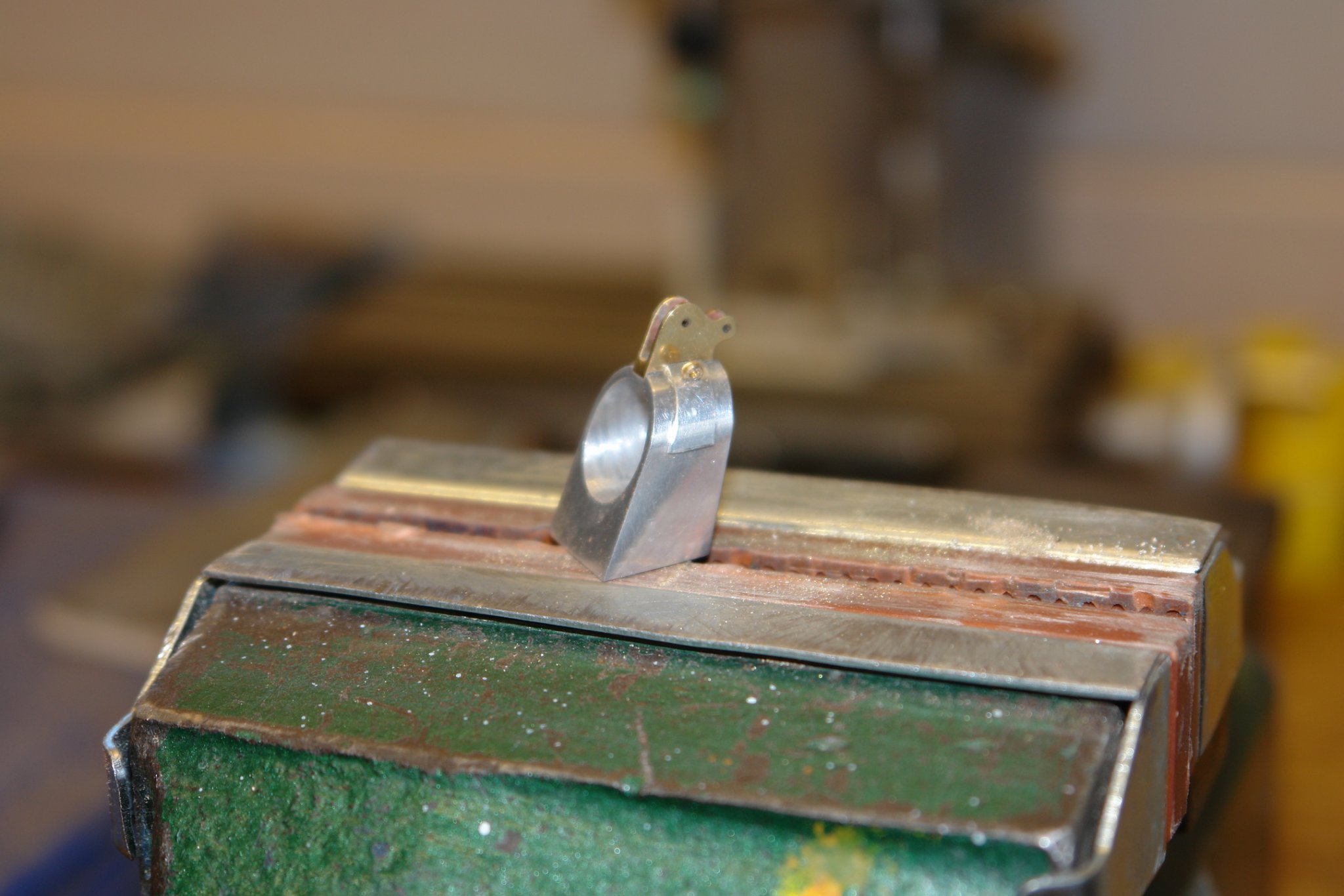
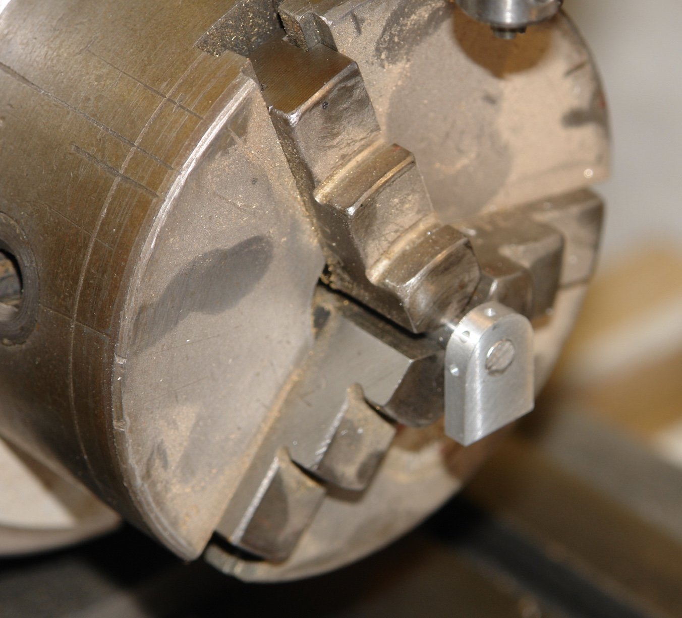
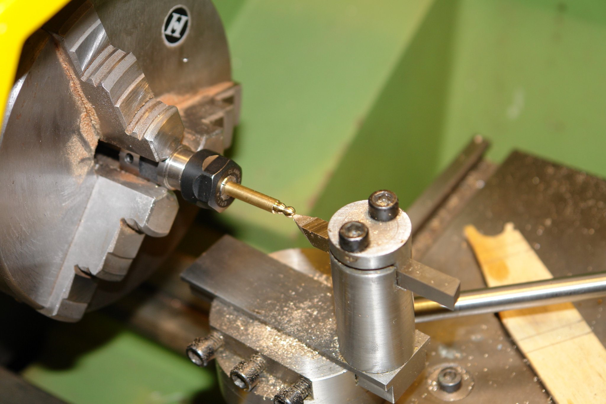
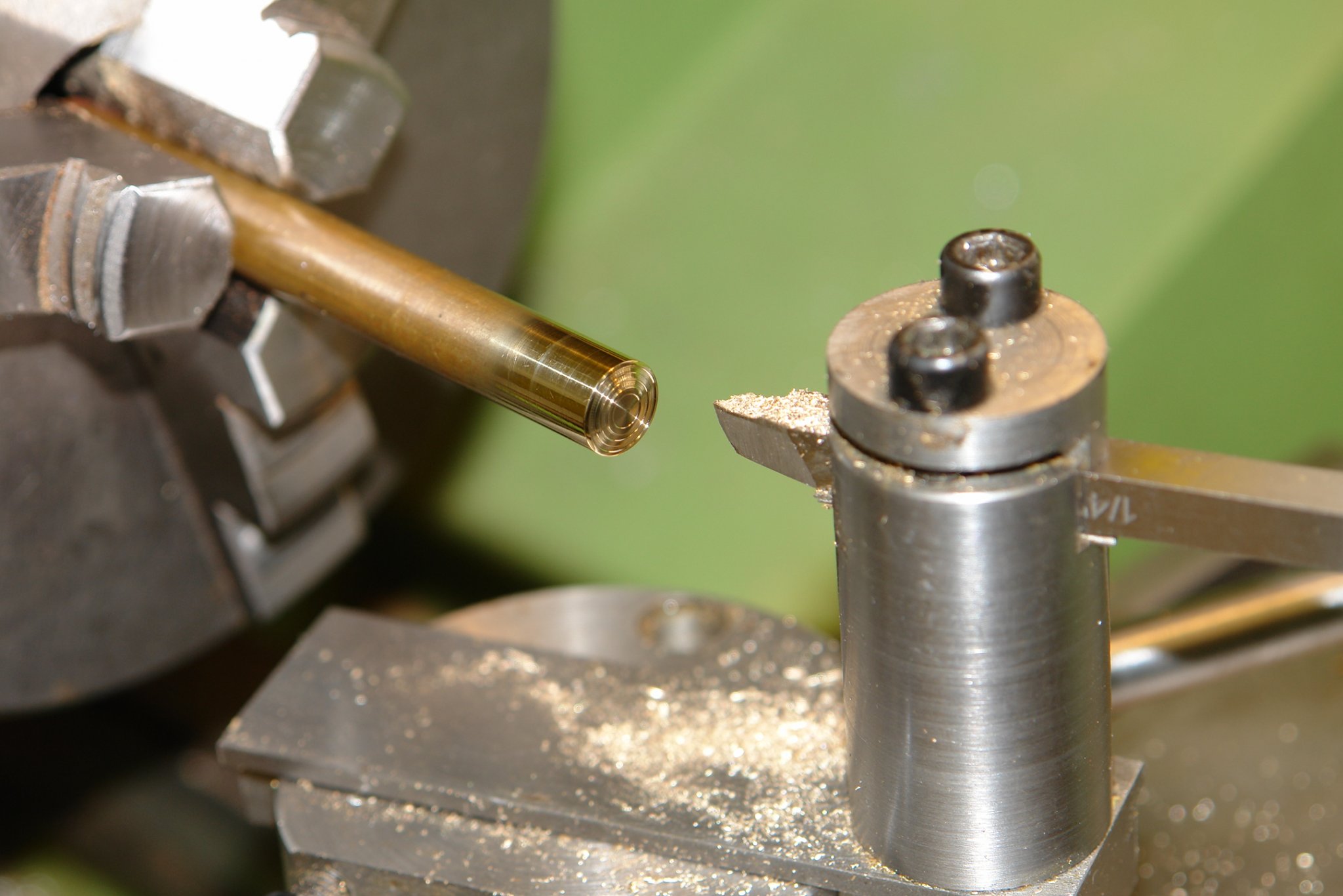
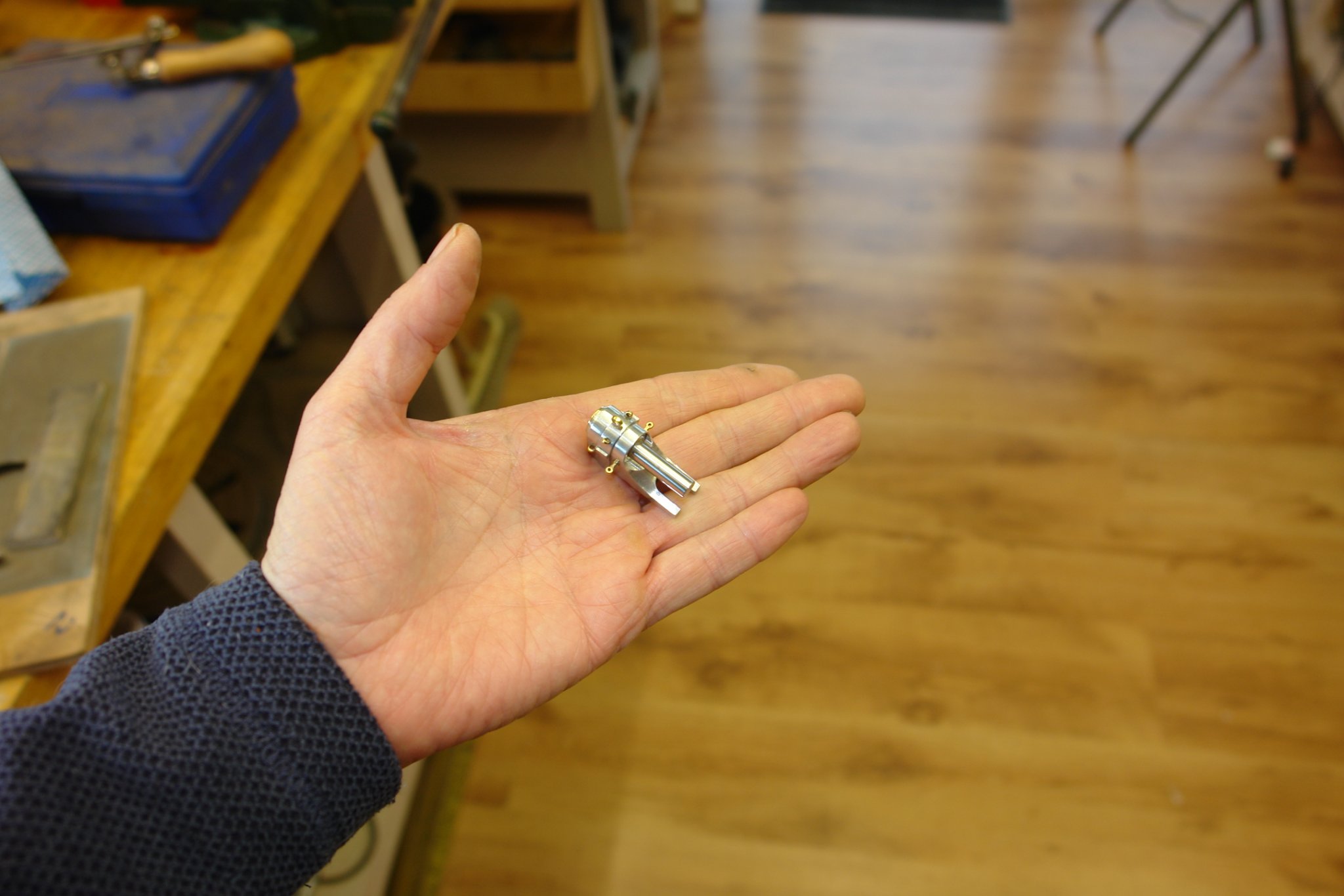
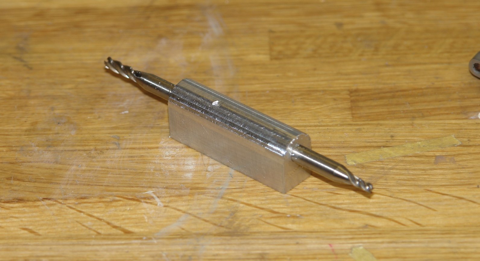
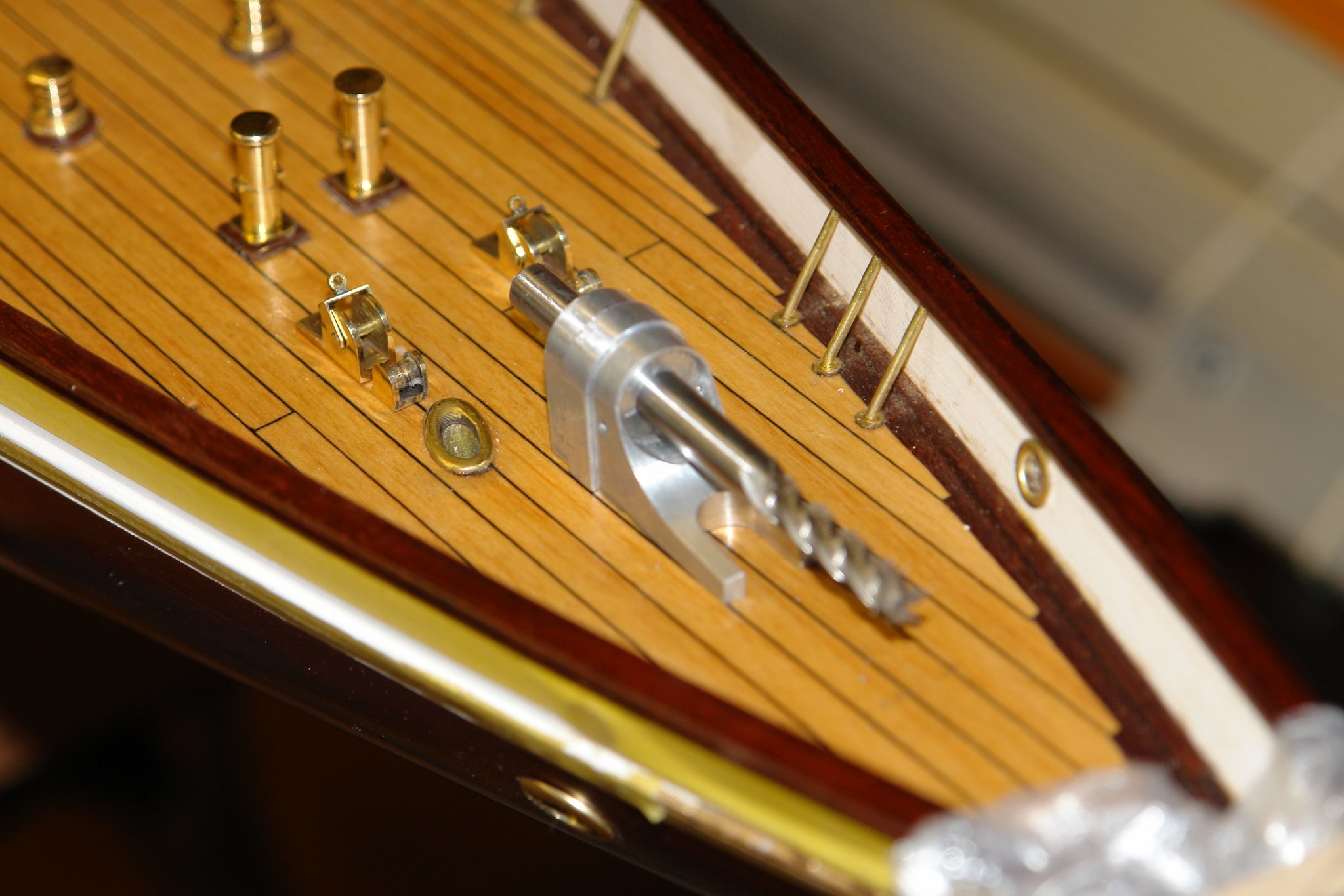
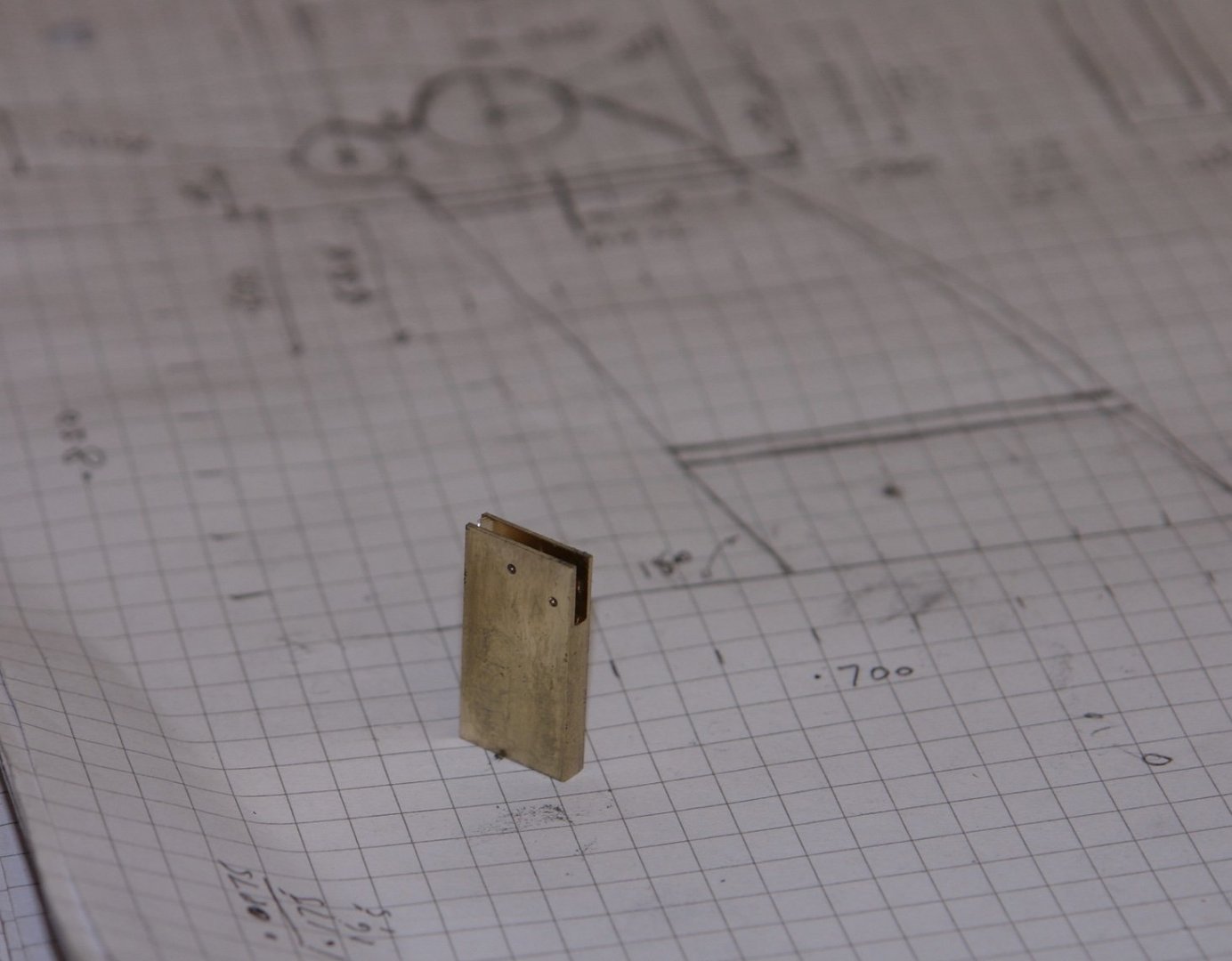
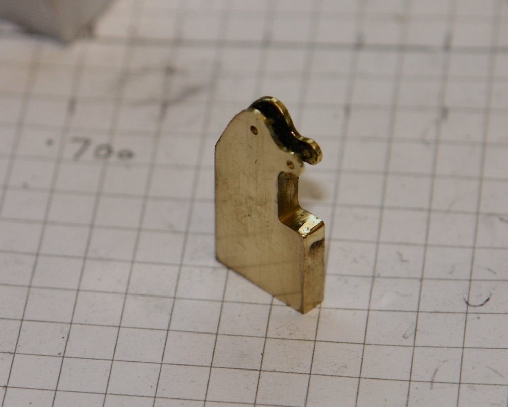
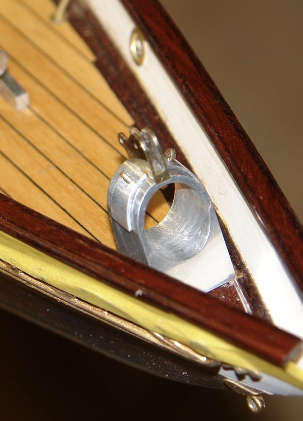
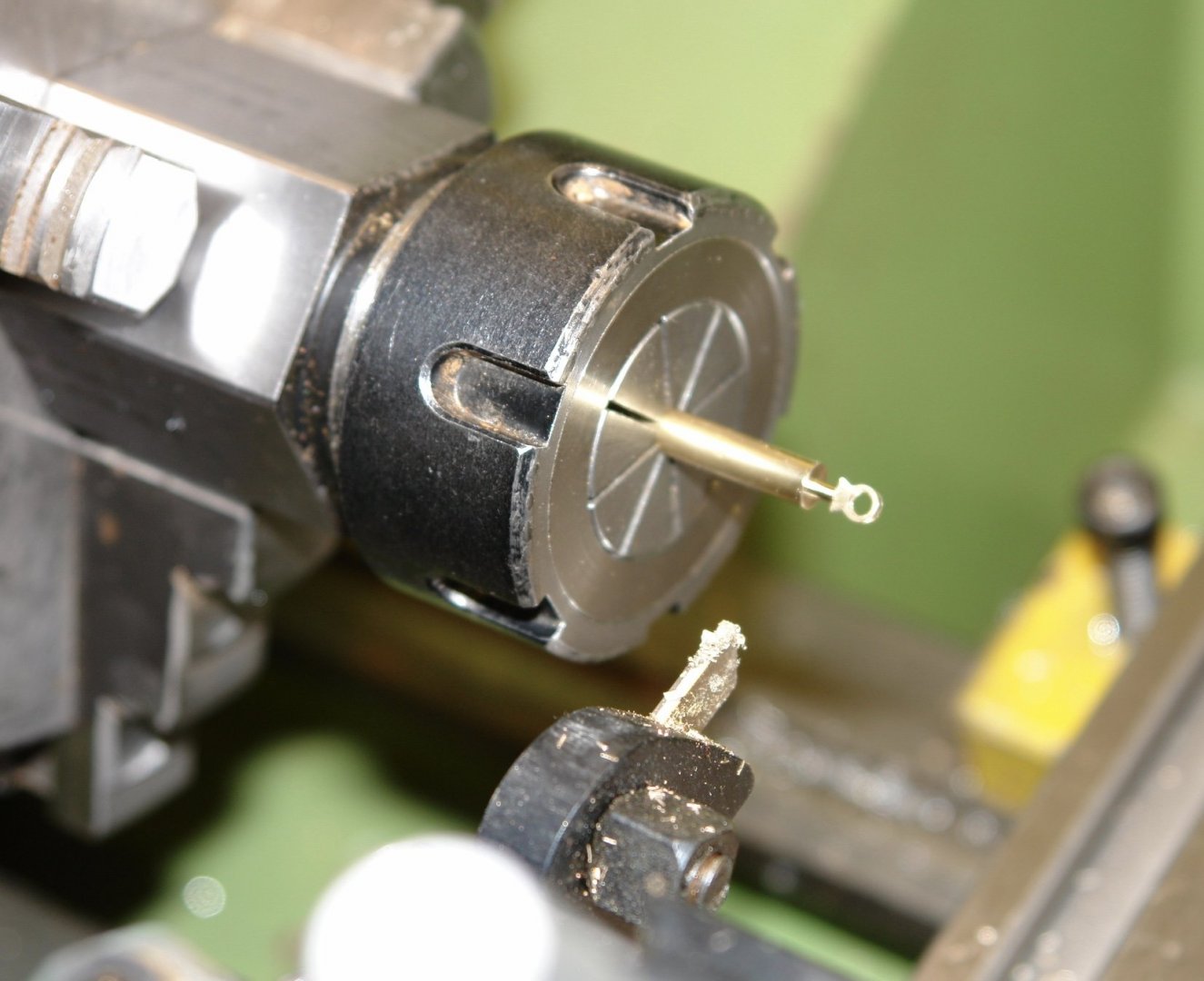
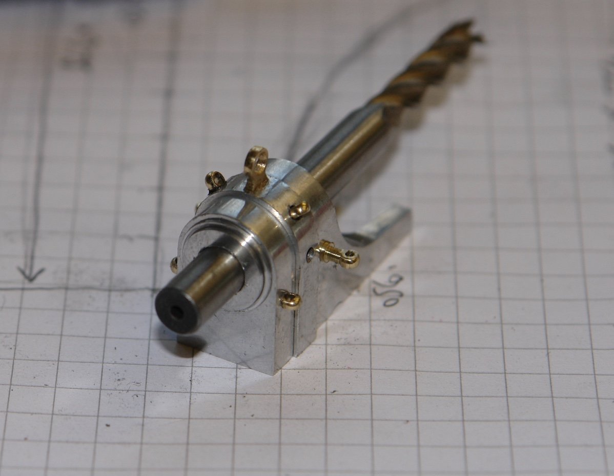
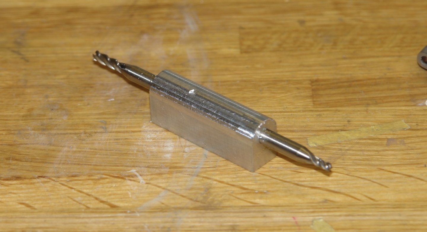
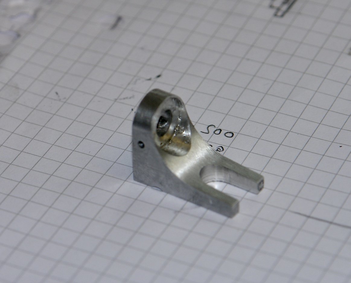
Thank you Steve / Richard. I'm glad the fires seem to be behind you Steve - it must be a relief. I spent some of the day in the workshop finishing the forestay anchor and watching the storm through the window. The top bracket was made from 1/2" x 1/8" bar. I stared by accurately drilling .040" holes at the centres of the 2 key diameters and then slitting the slot to create the "U" of the bracket I then made 2 sets of file buttons of .125" and .100" diameter respectively and filed the bracket to shape. I then drilled matching 1/16" holes in the bracket and the boss. I turned up a pin with a head of .070" diameter by .010" wide and a .062" shank. This was inserted from the bore of the boss and held in place by a scrap piece of dowel. The bracket was then placed over the 2 parts were soldered. I then needed to reproduce the thickened central section of the boss. As the bottom part of the boss is hidden I only needed to reproduce this feature on the top half of the hoop. I turned a piece of aluminium tube such that the bore matched the external radius of the boss. The wall thickness matched the up-stand of the thickened section i.e. .025". The tube was then mounted in the square collet block and the tapered profiles cut. These were then glued on to the boss with CA glue and .040" holes were drilled for small eyebolts. Eyebolts were made as previously covered and they were then attached.


-
Steve - Beautifully done and thank you for the brass splitting idea. Did you consider end milling the top half off and if so why did you choose the slitting saw technique.
-
Me too Richard - in 1969 / 1970, in my mind it's not that long ago, it's in my body that I notice the years.
-
Excellent metalwork on this build, very impressive.
-
Eberhard - the bracket will be in brass (to match the foot). I will inset a brass pin from inside the bore and solder it to the bracket. The slot is 1/8" wide - your dove tail cutters sound really impressive - where did you get them?
-
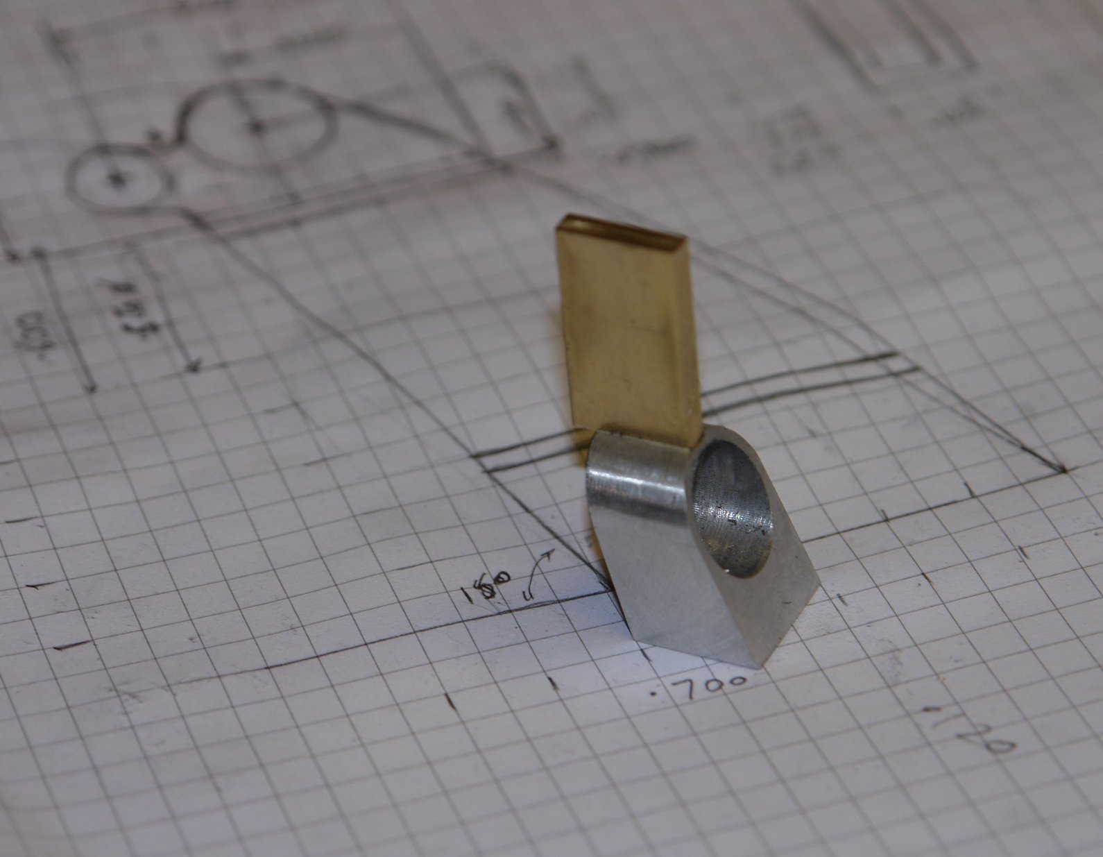
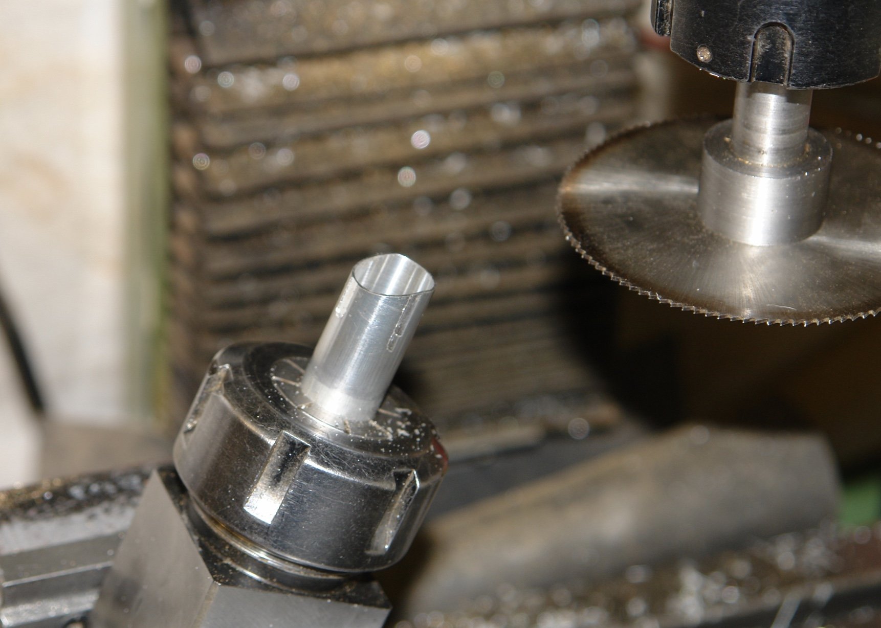
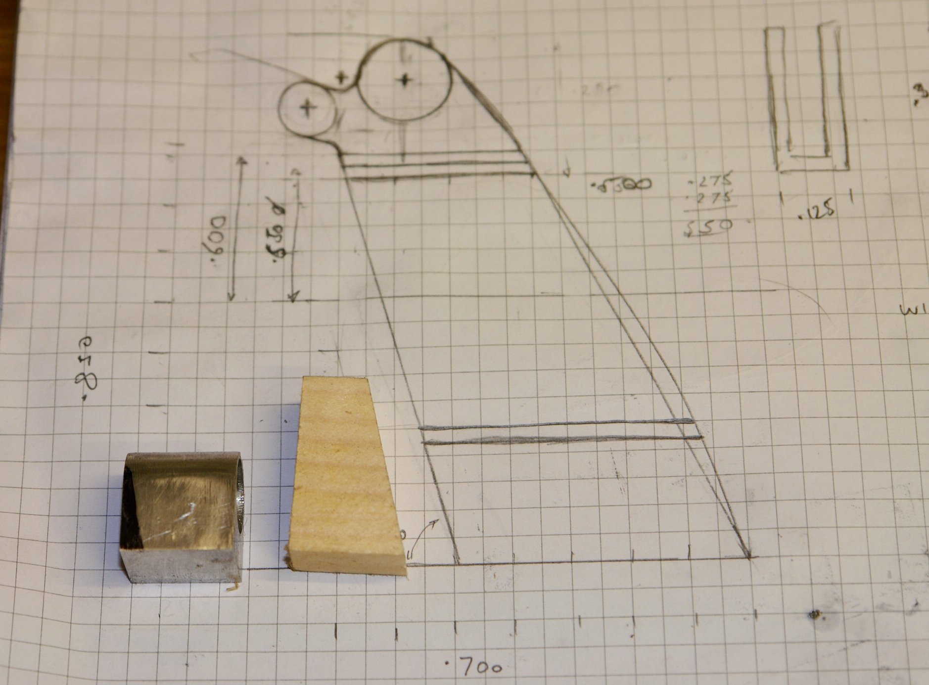
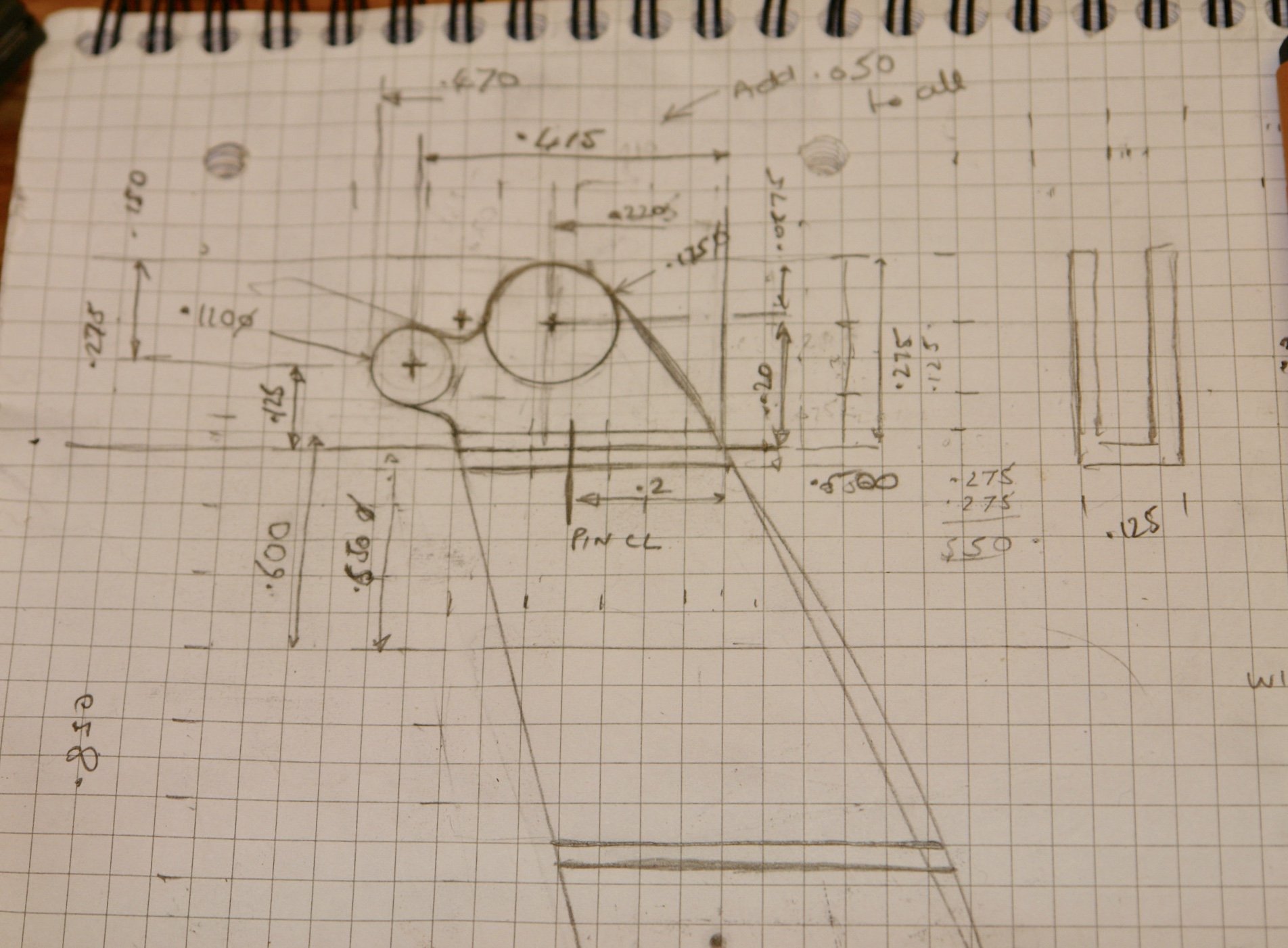
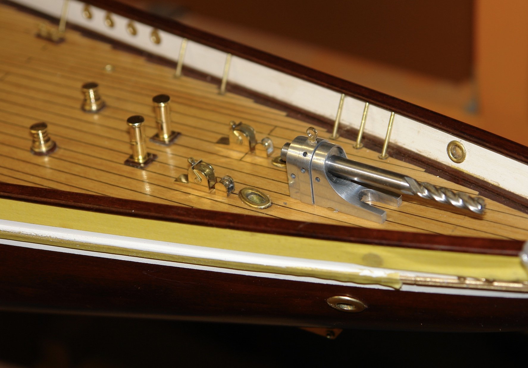
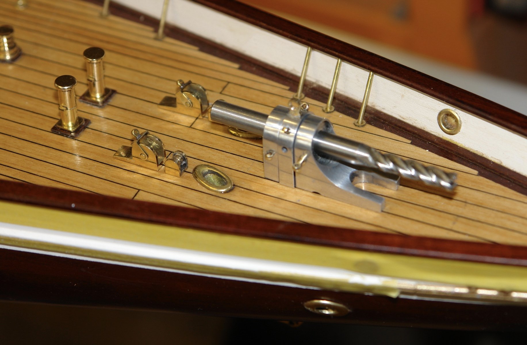
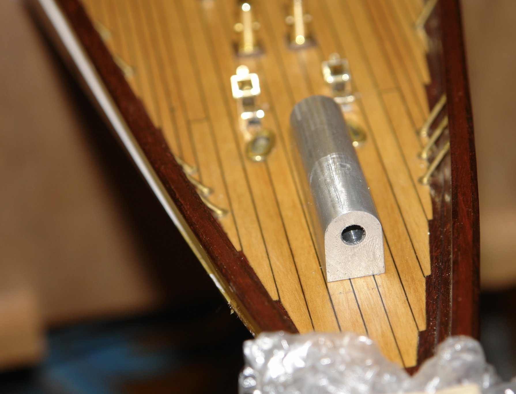
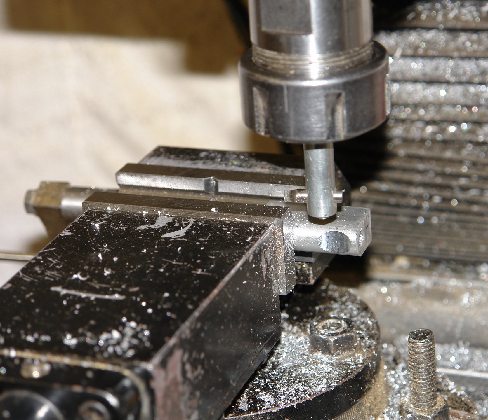
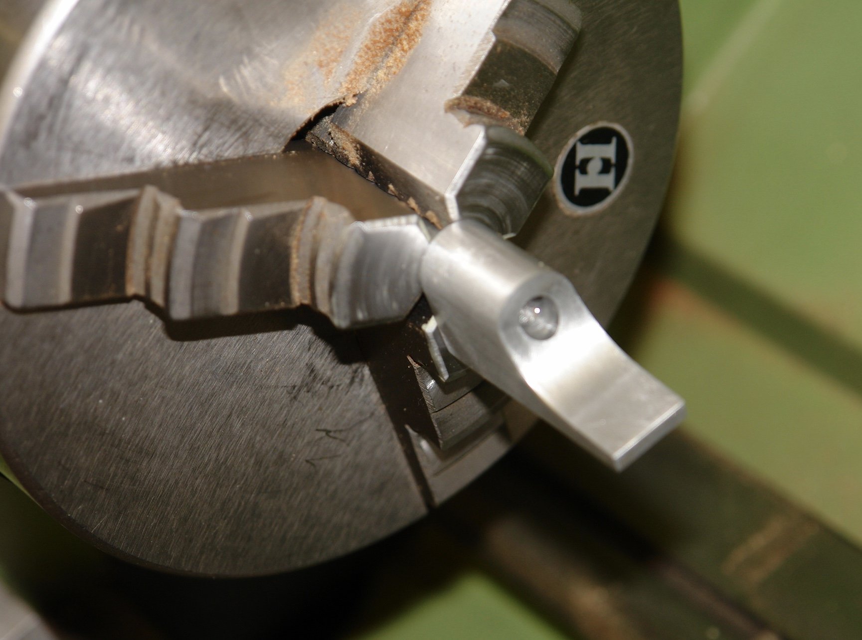
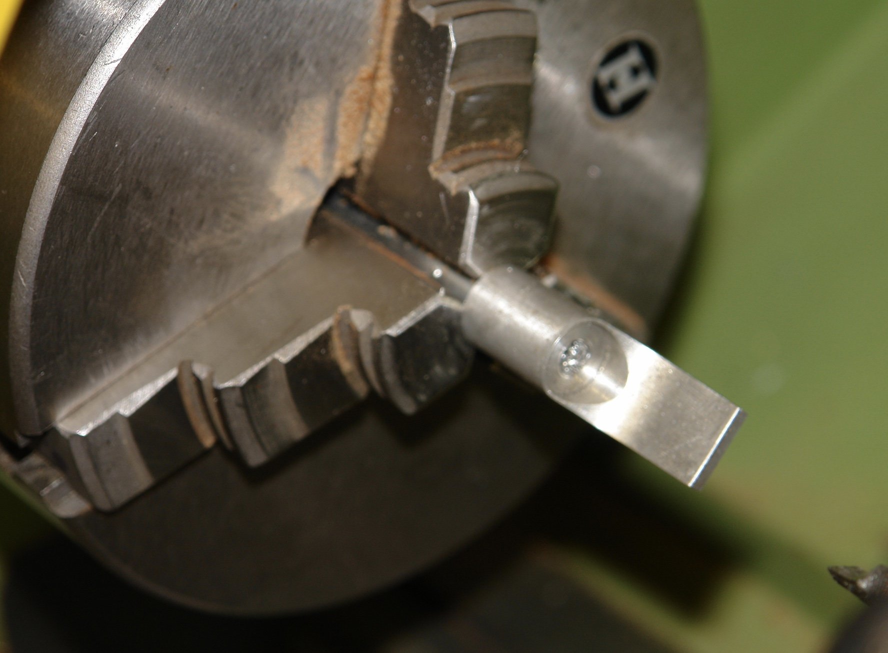
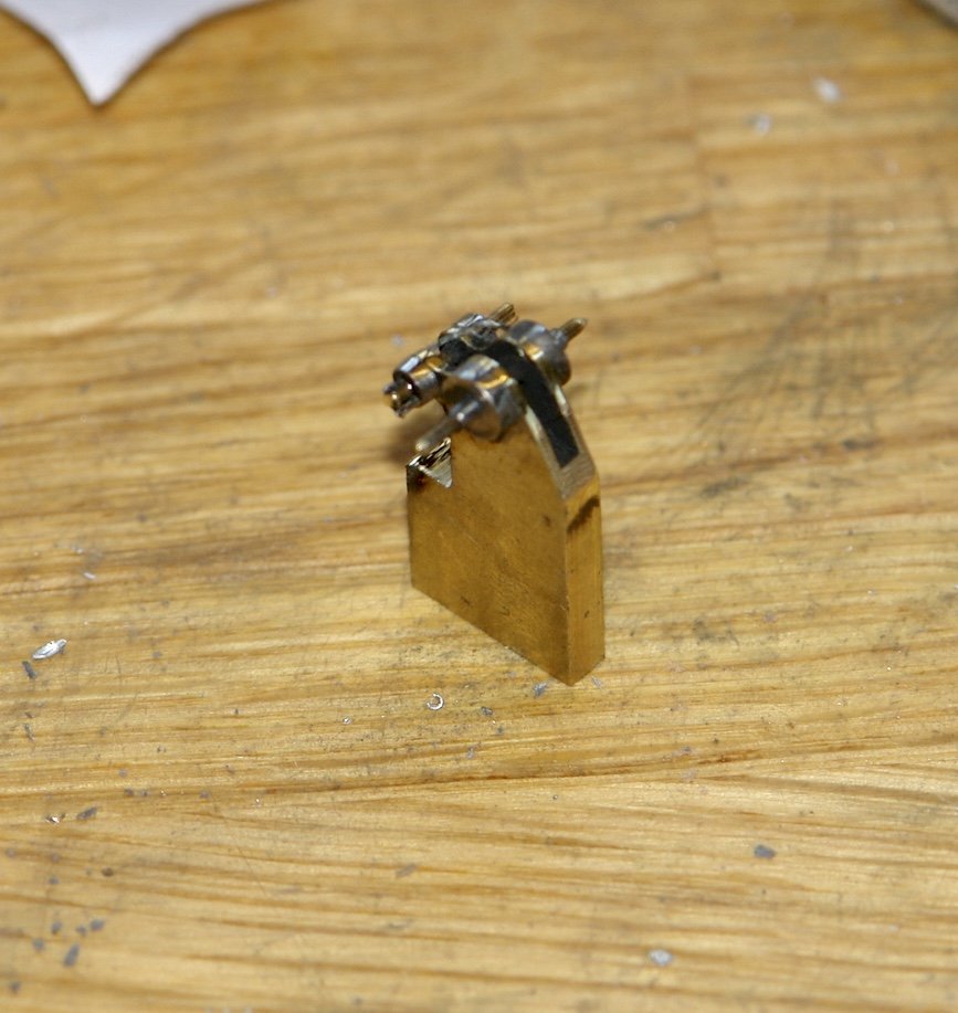
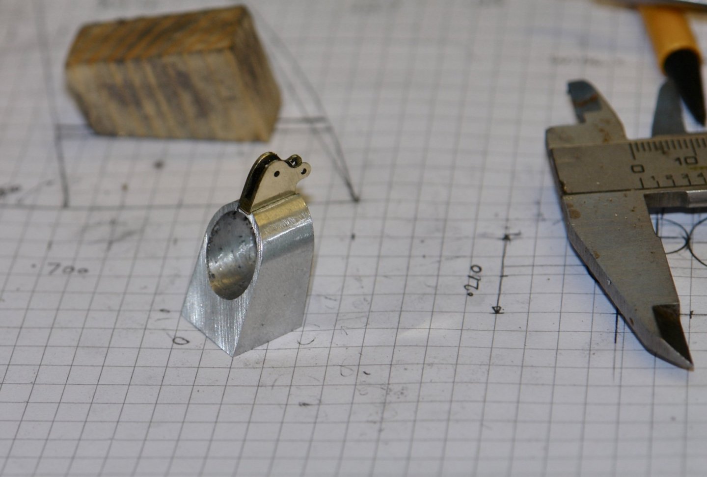
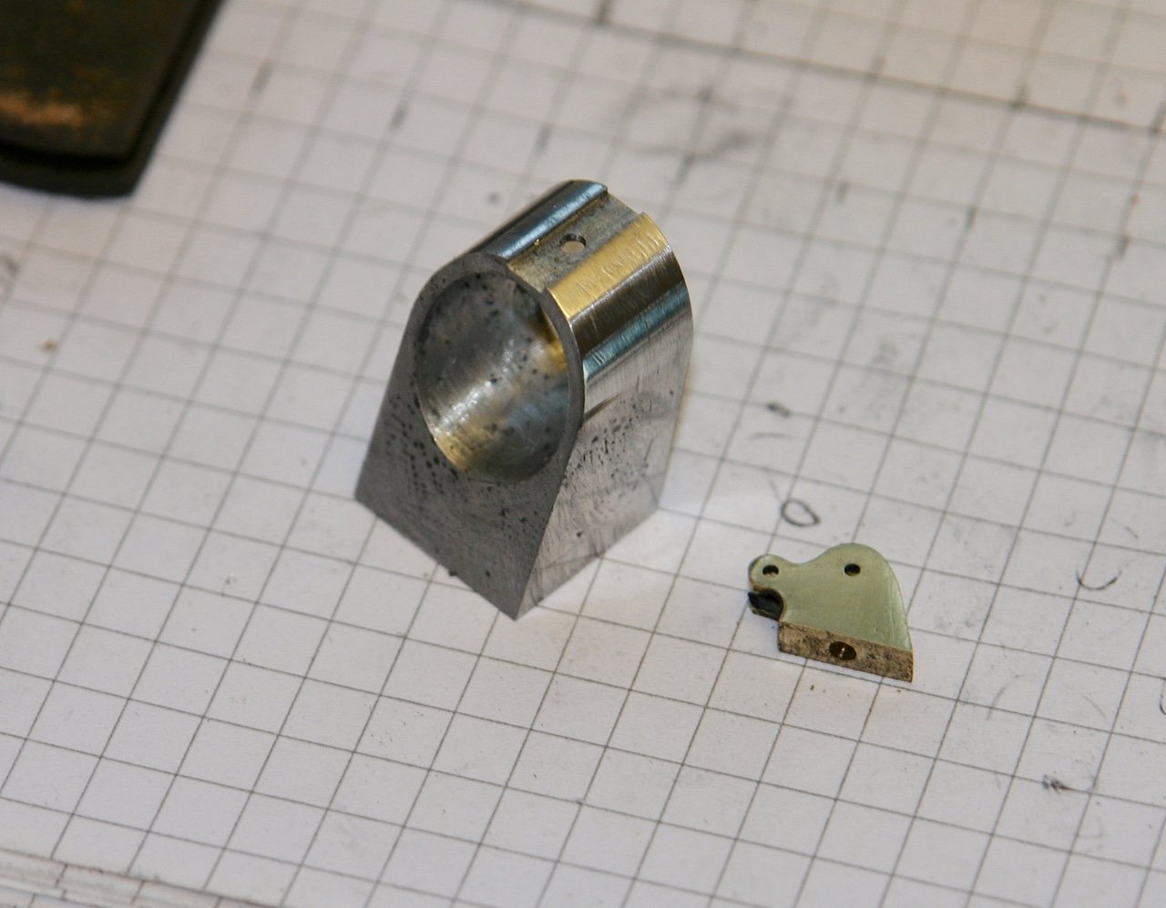
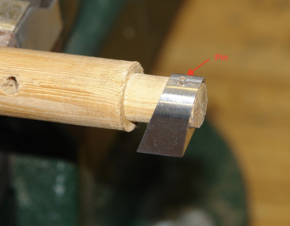
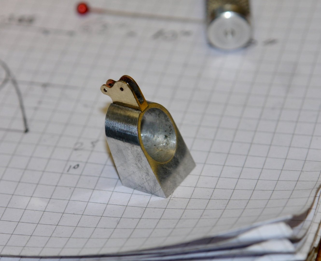
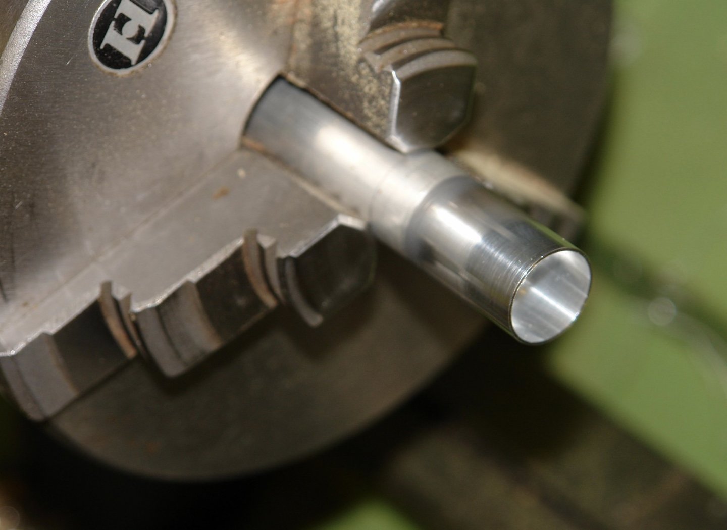
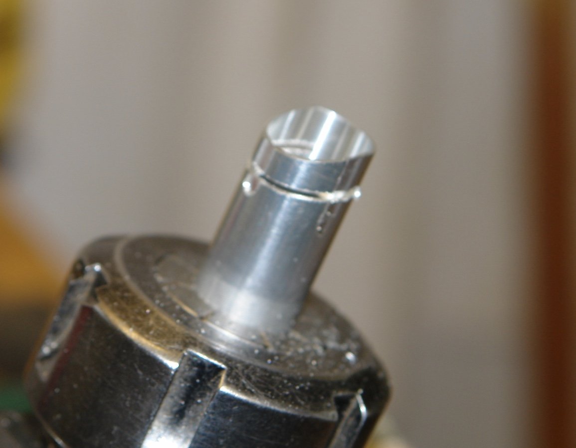
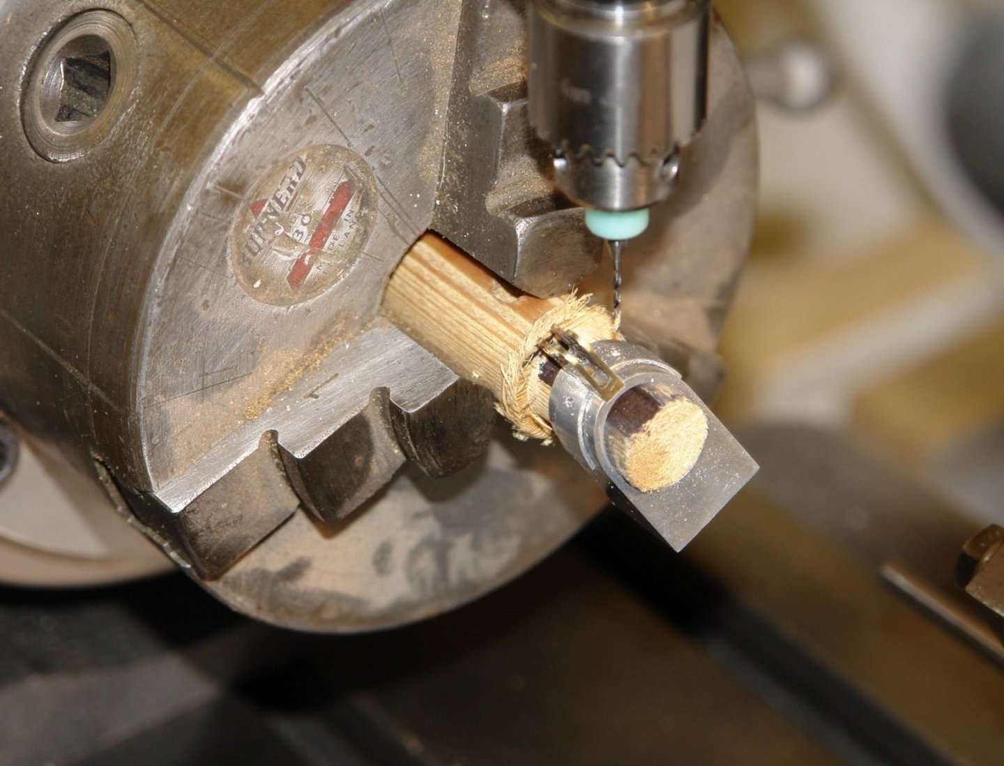
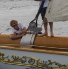
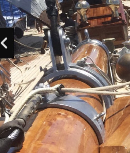
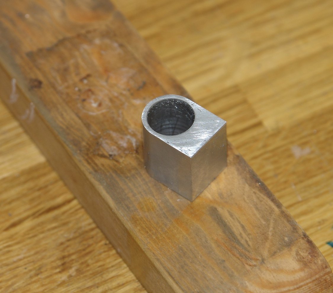
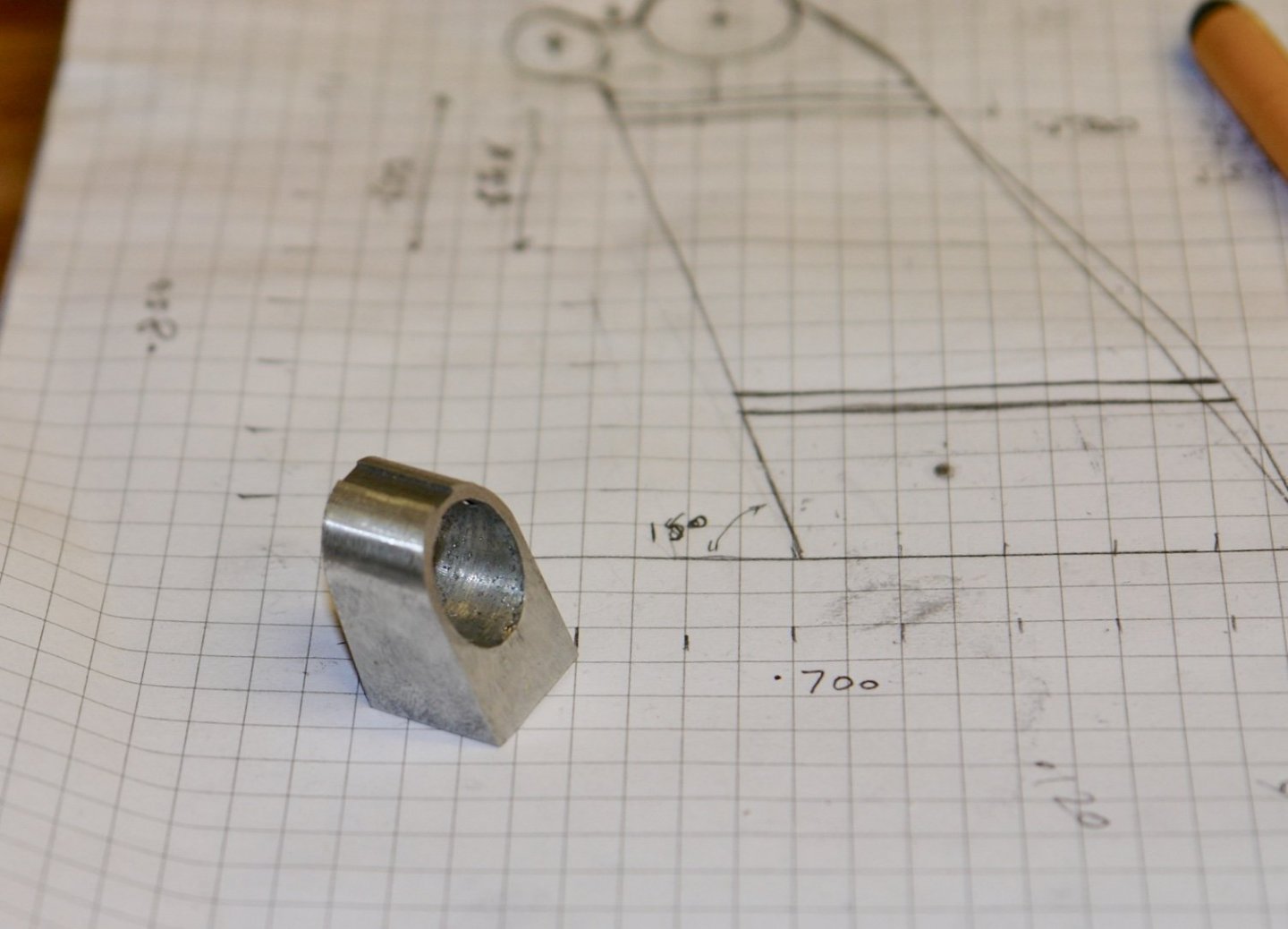
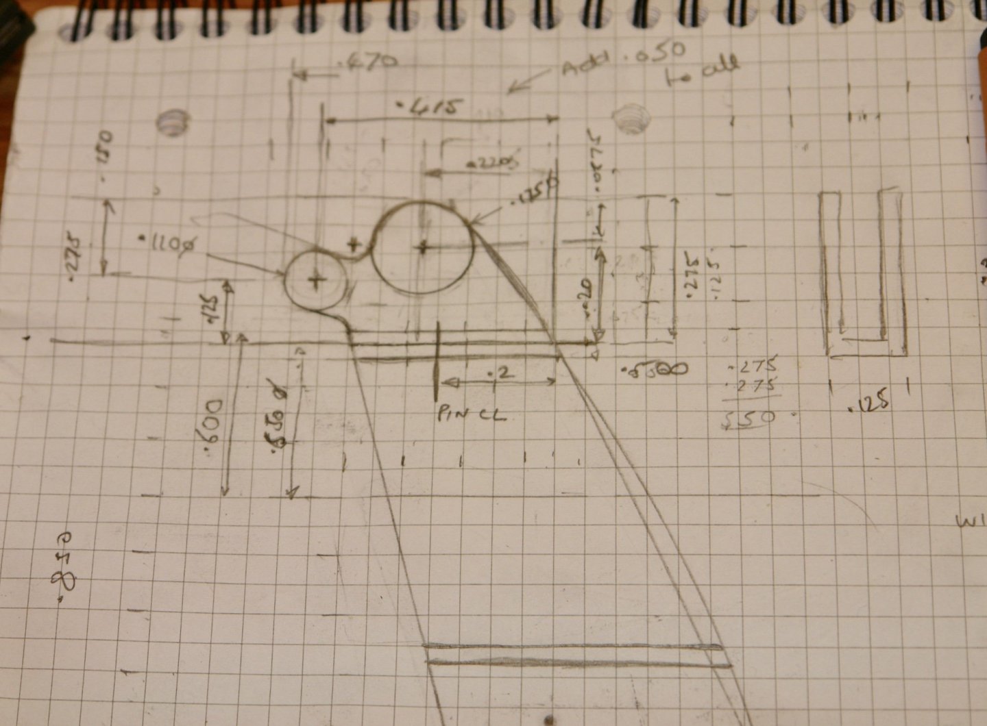
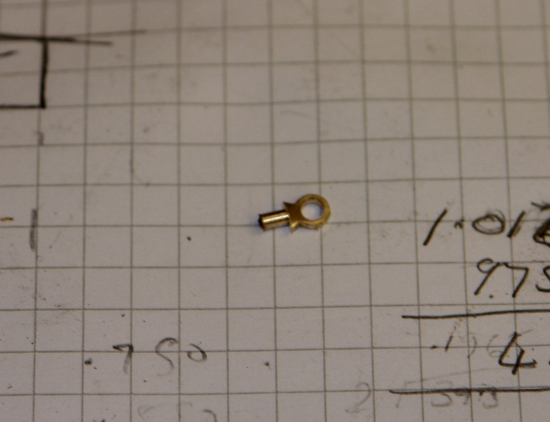
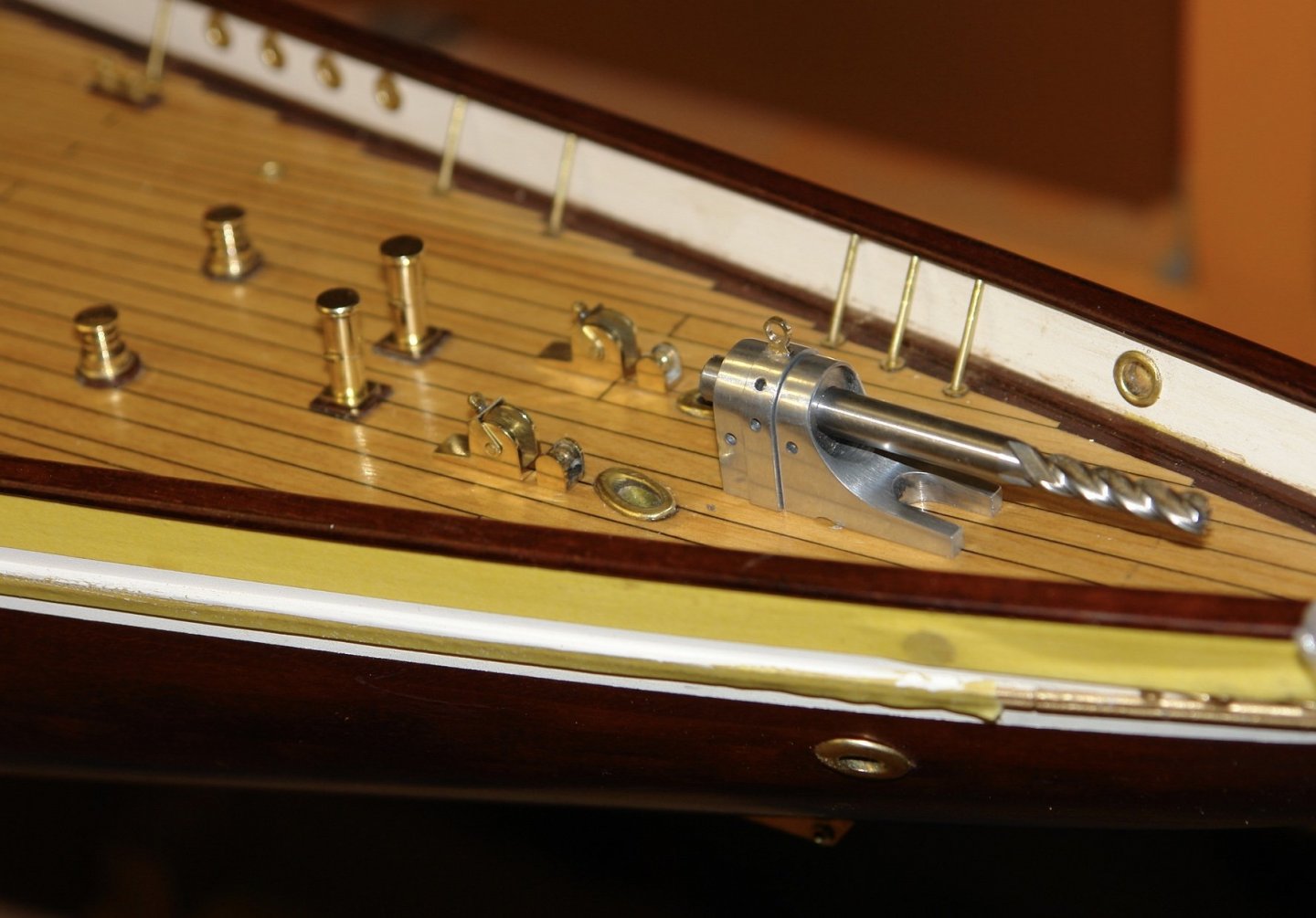
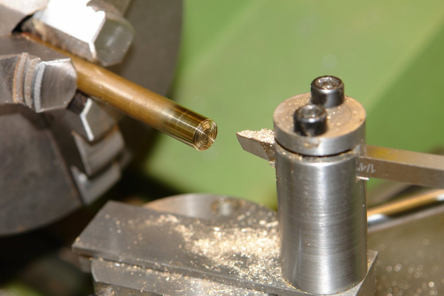
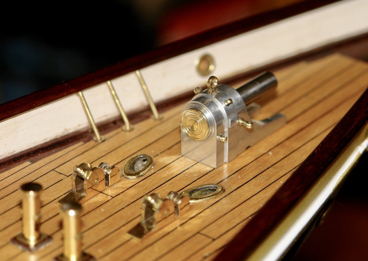
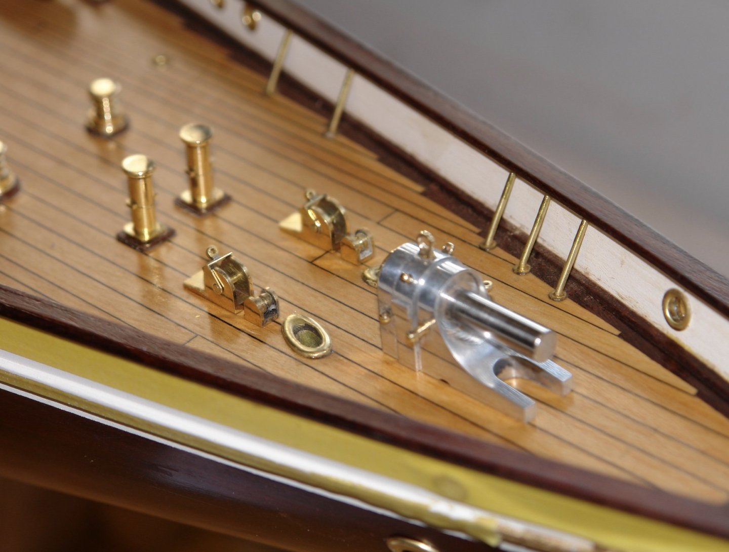
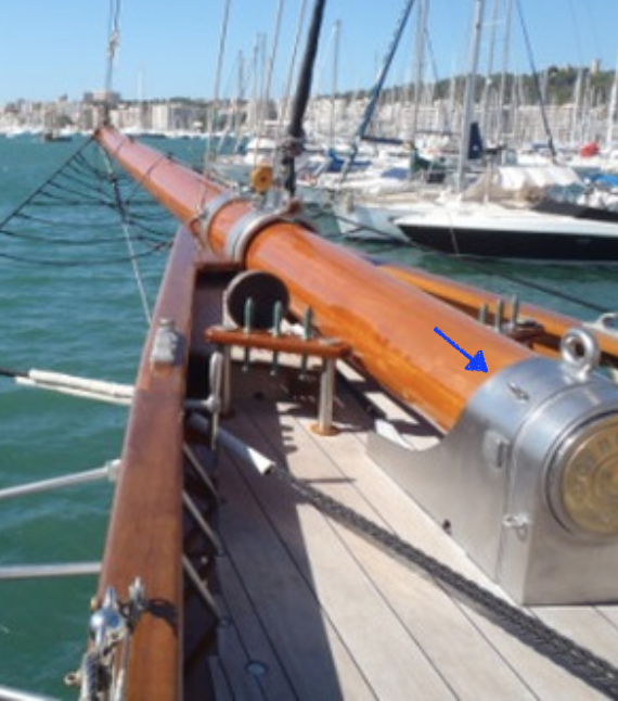
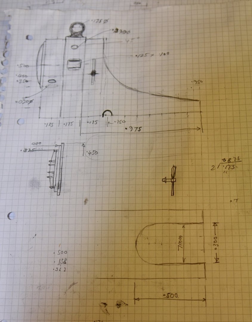
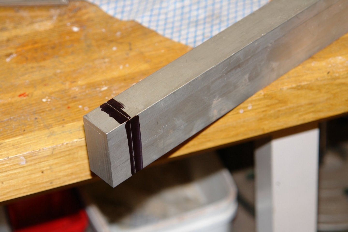
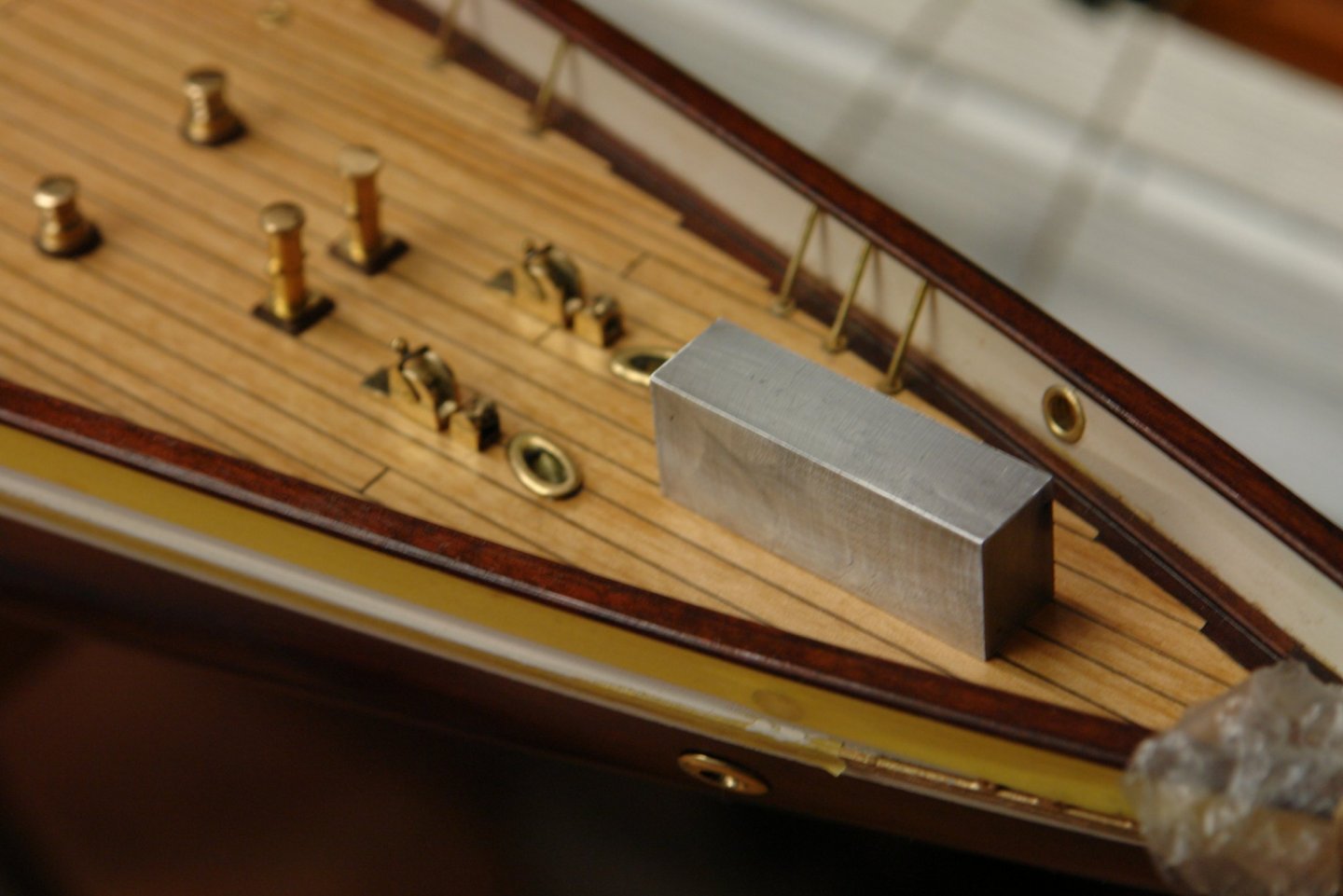
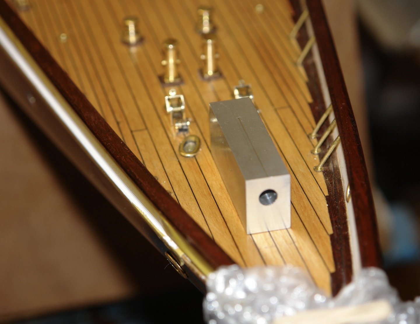
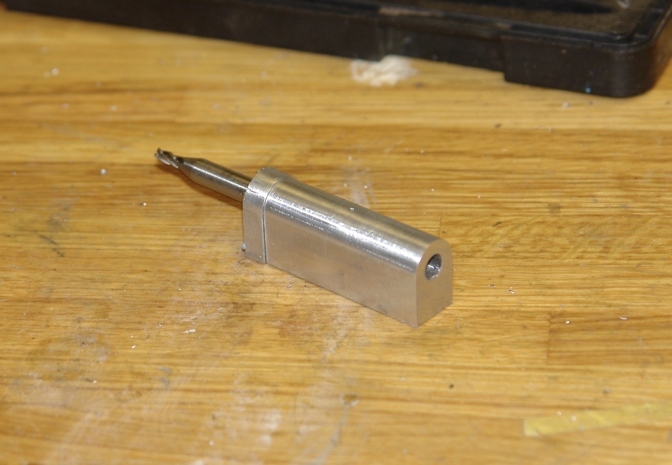
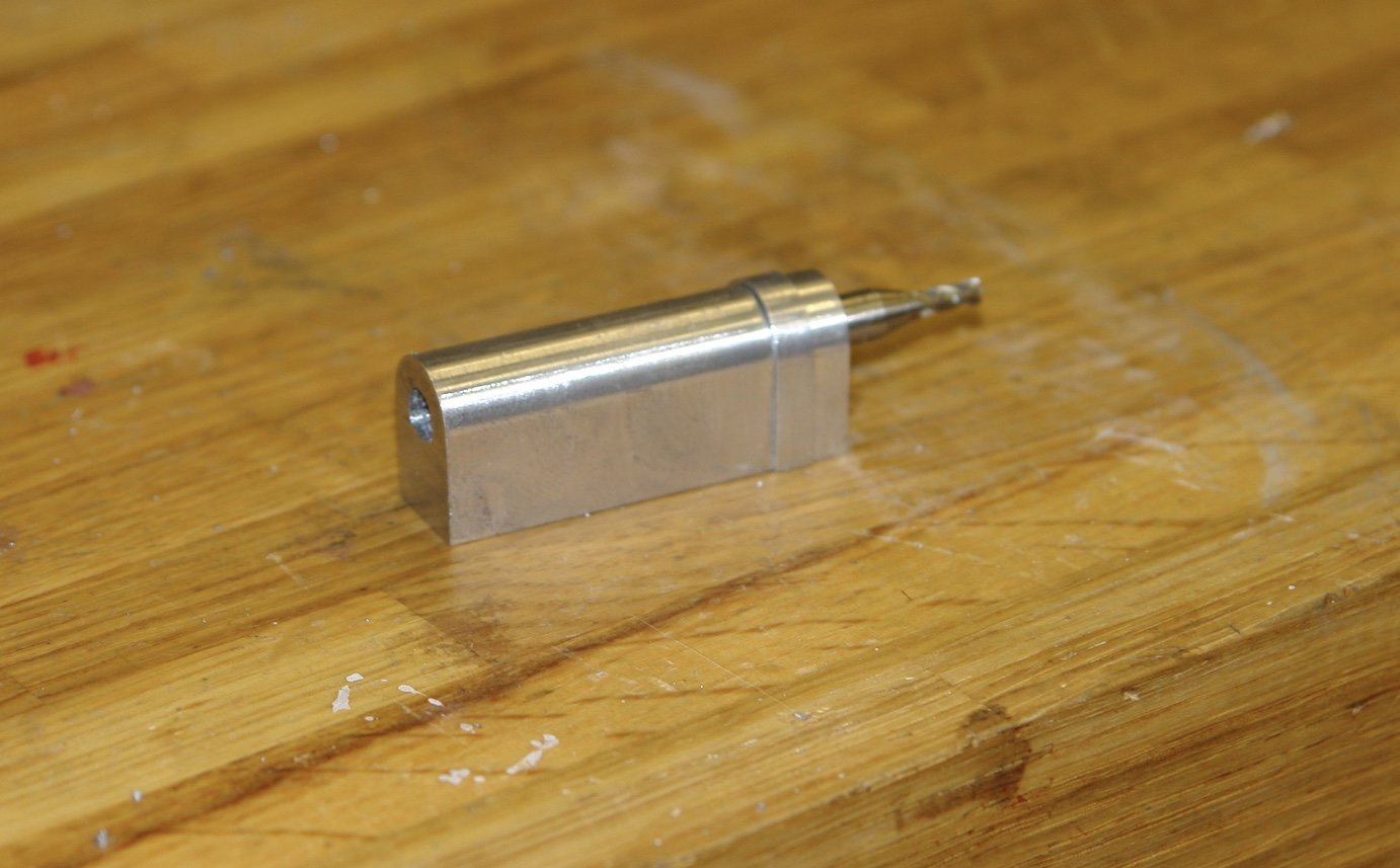
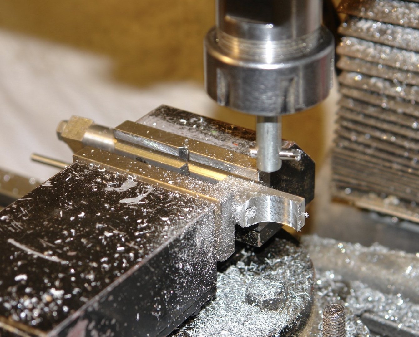
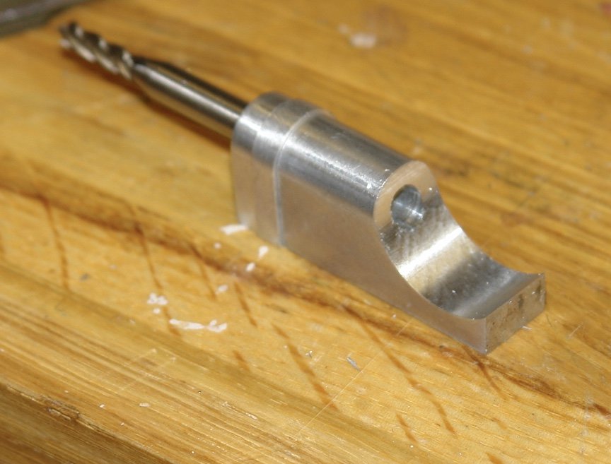
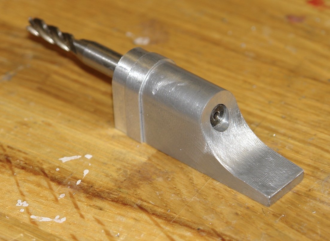
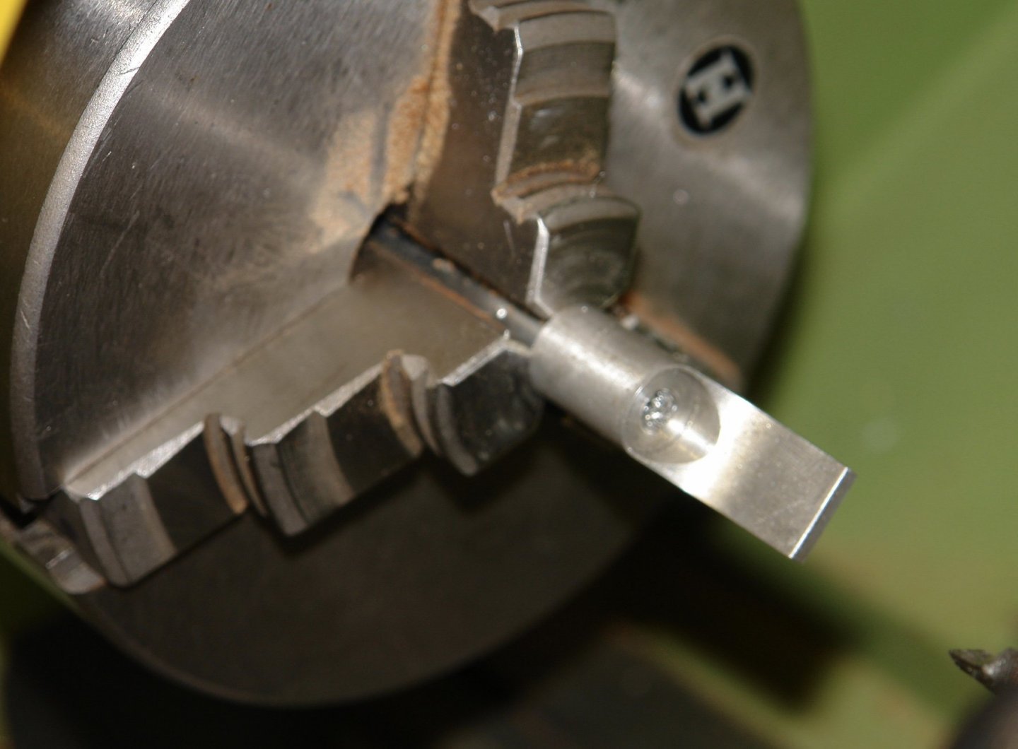
Moving on from the bowsprit foot the next component to have a go at is the substantial block of metal which anchors the foresail stay to the deck. As you can see in the photographs this is also made from "silver" metal. The lower portion of this feature is hidden below extensions to the capping rails and only the upper half of the hoop will be visible. It also has a thickened central section but in this instance I think I am going to adopt a different approach to that followed for the foot. The hoop of this component doesn't actually touch the bowsprit, the diameter of the bore being somewhat larger than the bowsprit itself. The size of this part can be obtained by scaling the plans and this together with the photographs provide sufficient information to produce a reasonable sketch. I started by sawing off another chunk of aluminium from my 2"x1" bar - such fun. The next step was to cut off the required length and bore the 0.5" hole to allow the 0.45" bowsprit to pass through. I looked through the scrap bin and found a piece of copper tube of 0.5" diameter to use as a mandrel for forming the hoop. As previously the hoop was formed on the mill by machining a series of flats. The hoop was then finished by draw filing to remove the flats. The angles to the front and rear of the component are different and hence produce a tapered form. To machine the angles I cut wooden spacers of the correct angle on the table saw and then used these to support the component in the milling vice. The angles were then cut using the face of an end mill. finally a slot was cut axially on the top of the hoop to take the "U" shaped bracket to which the the foresail stay is attached. More fun in the workshop this weekend, weather permitting. We are importing an American storm over the weekend - lashing rain and storm force winds. Dog walking should be fun.

-
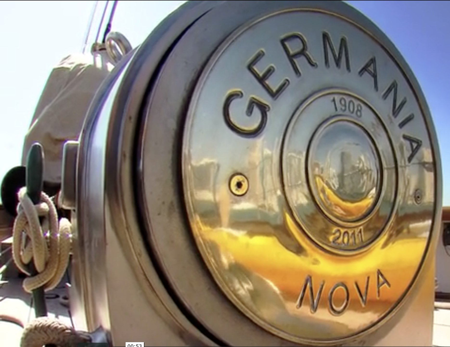
Thank you all for taking the time to comment. The bullet idea looks the best bet for the lettering and I wait with anticipation for a arms manufacture called Germania to commence ammunition manufacturer. I also like Marks suggestion of using subterfuge to con the casual observer, however I'm not sure it would work on any of the shipwrights at MSW.
-
Very nicely done Eberhard. Excellent detail noting the small scale that you are working at.
-
Lovely work on the lock Michael - exquisite - only to be improved by making the end plate screw slots vertical.
-
I too like the thimble technique - must try it some time - also must remember to build bigger scale next time.
-
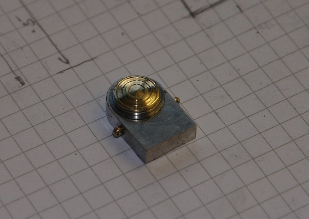
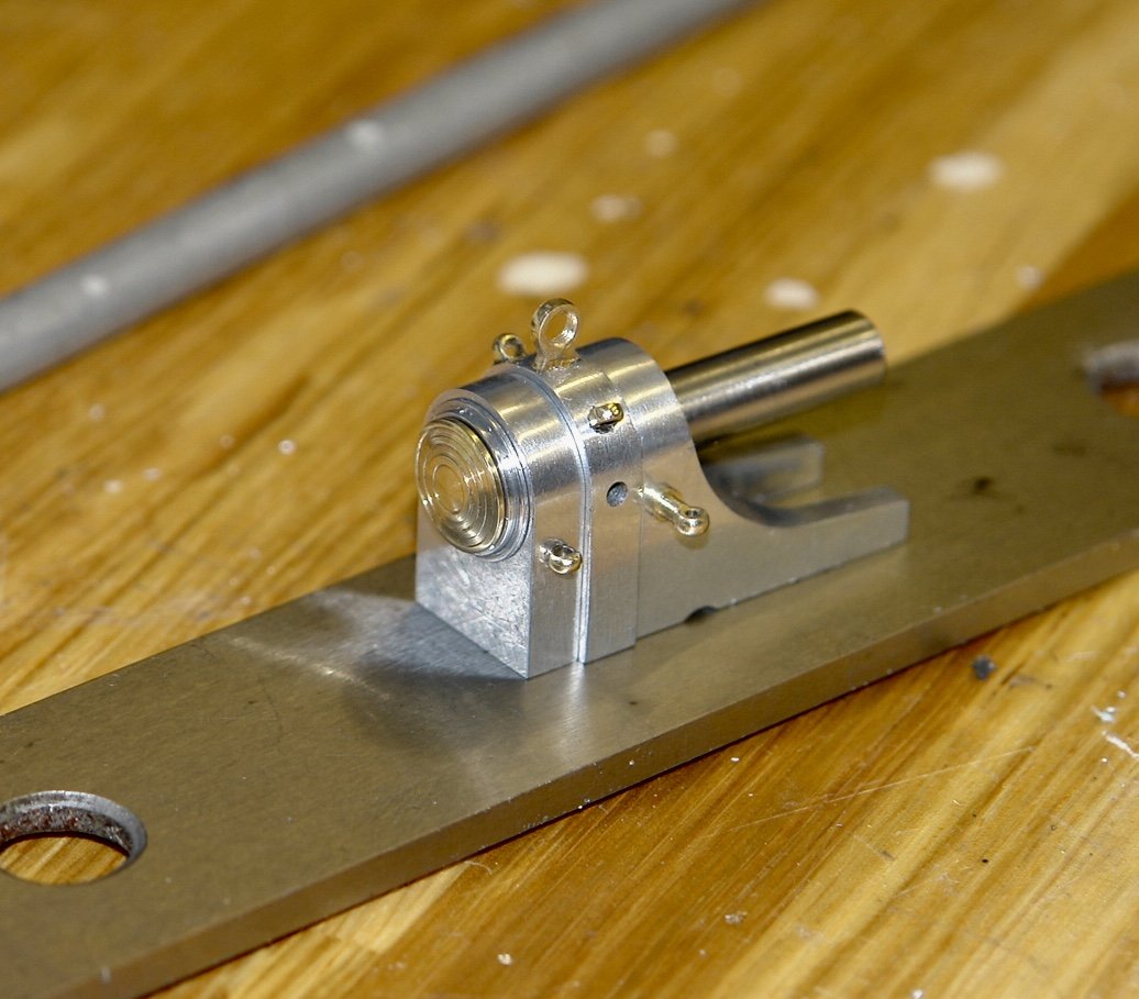
Today I managed to finish the bowsprit foot. The larger middle section of the foot has 5 holes for 1 large eyebolt, 2 small eyebolts and 2 oblong bosses. I glued the part to a rod and mounted it on the mill rotary table and drilled 5 holes of 1/16" diameter. I next made the large eyebolt. The outside diameter was .150" and rather than make a profile tool I decided to use my ball turning tool to create a sphere. This was then thinned to .04" wide while mounted in a hex collet bock on the mill and a 0.1" hole was drilled to form the hoop. Finally the part was moved back to the lathe where a 1/16 spigot was turned. The eyebolt was parted off using the piercing saw. The eyebolt was glued in place with CA and 2 holes were drilled in the rearmost of the 3 parts to take 2 more smaller eyebolts. The other eyebolts (4 in total) of .09" diameter were made with the profile tool covered in an earlier post. These too were glued into the relevant holes. 2 further eyebolts were made with extended spindles to take the belaying pins and these were glued into the front of the 3 body parts. The flange at the rear was then turned (from aluminium) with a 6mm hole for location. I used the ball turning tool to form the the dome of brass boss and create the raised circular features. This was then parted off with a short 6mm spigot on the opposite side to the dome. At this stage I did a bit of polishing and then glued the 3 body parts together on a 6mm steel shaft. This shaft will fit inside a bore drilled in the rear end of the bowsprit. It was at this stage I realised I had forgotten the oblong plates so these were made and installed.


-
I obviously misled you Druxey. I did the machining over 2 days. Dog walking limits my performance. Michael - yes you would think that the cutting forces would break the bond but I have never experienced a failure. Modern glues are really impressive aren't they. A number of you have commented and offered suggestions on lettering. I agree that your suggestions are quite feasible. The issue for me is that the size is so small that without a magnifying glass an observer wouldn't notice the lettering. Hmmmm! Looking at your work I don't think the skills would be much of an obstacle, and machines can be bought relatively cheaply these days. Eberhard, Mark, Bedford - thank you for your feedback and suggestions.
-
Yes Kevin - the dog has that effect on me as well.
-
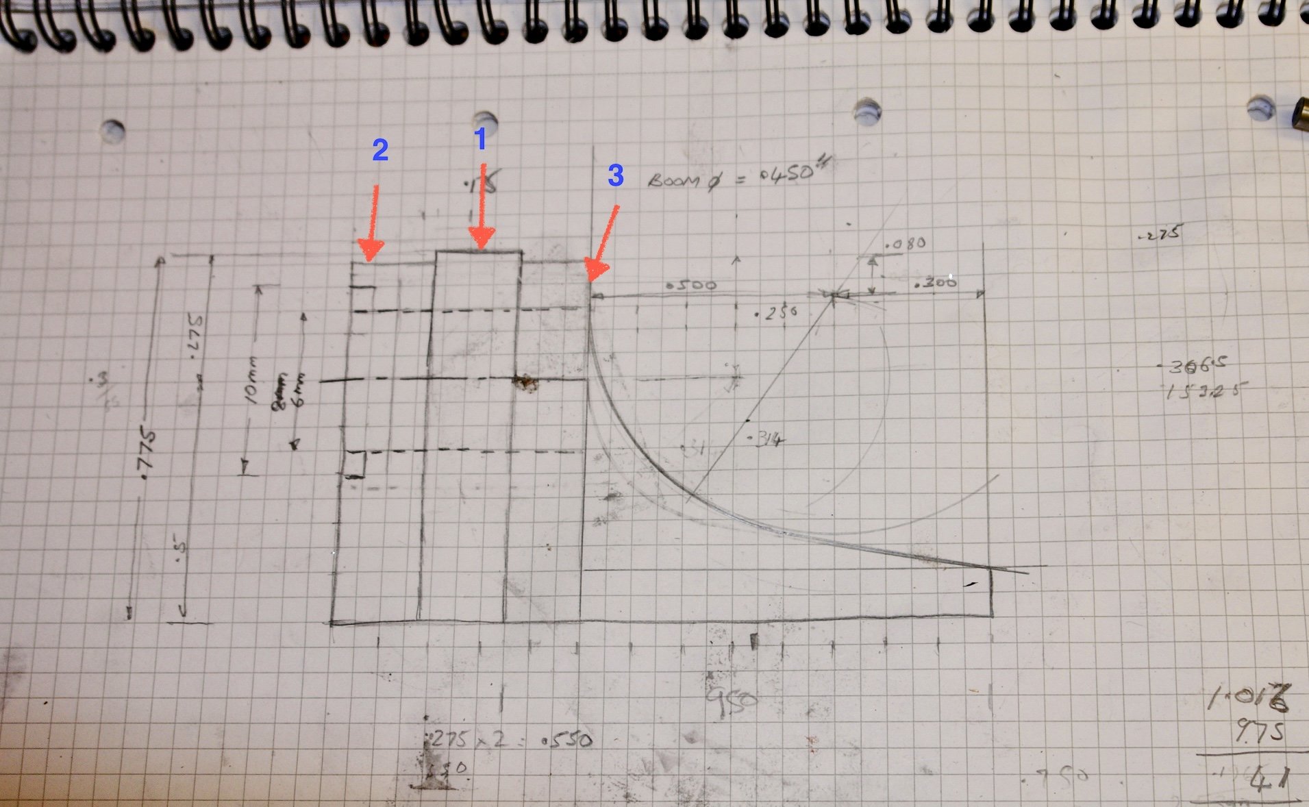
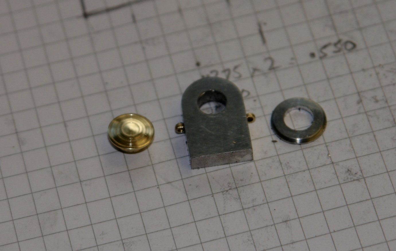
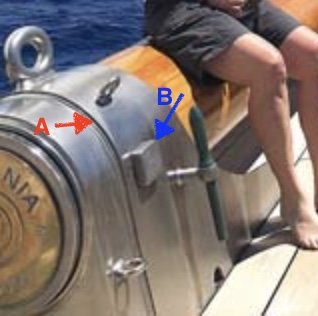
For a while I have been thinking that the bowsprit foot would make an interesting project and so I decided to tackle it next. I find that solving machining problems is a lot of fun and in this case the step in the profile of the foot (Item A) caused a bit of head scratching. The oblong boss (item B ) was a lesser problem to resolve. The brass name plate at the back of the foot is quite nice but at scale size the larger letters are circa .05" high so I don't think I will be trying to reproduce them. Through a combination of plans and photographs I was able to sketch and size the foot. I decided the best way to produce the step was to make the foot from 3 parts labeled 1,2 and 3 in the sketch. The foot on Germania is made from a silver coloured metal which could be stainless steel but my guess is it may be aluminium. The colour makes it quite a pronounced feature so I decided to reproduce this by making the foot predominantly from aluminium. I started the manufacture by cutting a 0.650" wide block from a 2" x 1" piece of aluminium bar. I just love hacksawing thick metal sections like this!!!!!! Having cut the block I reduced it to .55" wide by .775" high by 2" long. I then drilled and reamed a 6mm hole through the block .5" from the narrow edge. Apologies for the mixed units my reamers are all metric. I then used the reamed hole as the location for milling the outer radius of the top. The next step was to slice off and finish to thickness the central part of the foot - item 1 in the sketch. With this removed the surface of the remaining material was reduced by .025". A further slice was then cut off and finished to size to create item 2. The next step was to start profiling the shape of item 3. To do this I needed a 1" diameter cutter. As I don't have one I used a fly-cutter instead. I set this up by positioning the centre line of the cutter spindle directly above the edge of the machine vice and then indexing across by .5". I then set the fly cutter blade against the side of the vice to give me a fly-cutter diameter of 1 inch. The kick up at the front was then removed on the mill before the curved face was finished by draw filing. Part 3 was then glued to a 6mm steel rod and transferred to the lathe. Here the face of the 6mm hole was cut back with a boring tool to form a flat seat of the bowsprit. With this done I applied a little heat to break the glue bond and then hacksawed and milled part 3 to length. Finally I removed the centre of the foot to form 2 toes and drilled the holes for attaching the belaying pins. The part finished foot was then assembled. I hope to finish it tomorrow.


-
I enjoyed catching up Marsal. Very fine work indeed.
- 589 replies
-
- 2
-

-
- le gros ventre
- cargo
- (and 1 more)
-
Nicely done - you will find the collet blocks more and more useful. I even tried to find an octagonal one recently but with no success so I am constrained to using the square block with a "V" block.
-
Yes Oddball it is surprising what little you need to get started. I will be interested to see how much your tool collection has expanded in a few years time. If you are like many of us you will be looking for a bigger workshop by then.
-
To mirror everyone else who has commented - stunning work. Well done Michael. The most fun part is solving problems.