KeithAug
-
Posts
3,985 -
Joined
-
Last visited
Content Type
Profiles
Forums
Gallery
Events
Everything posted by KeithAug
-
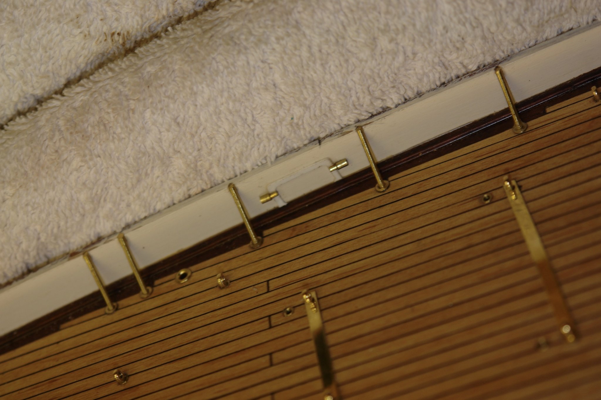
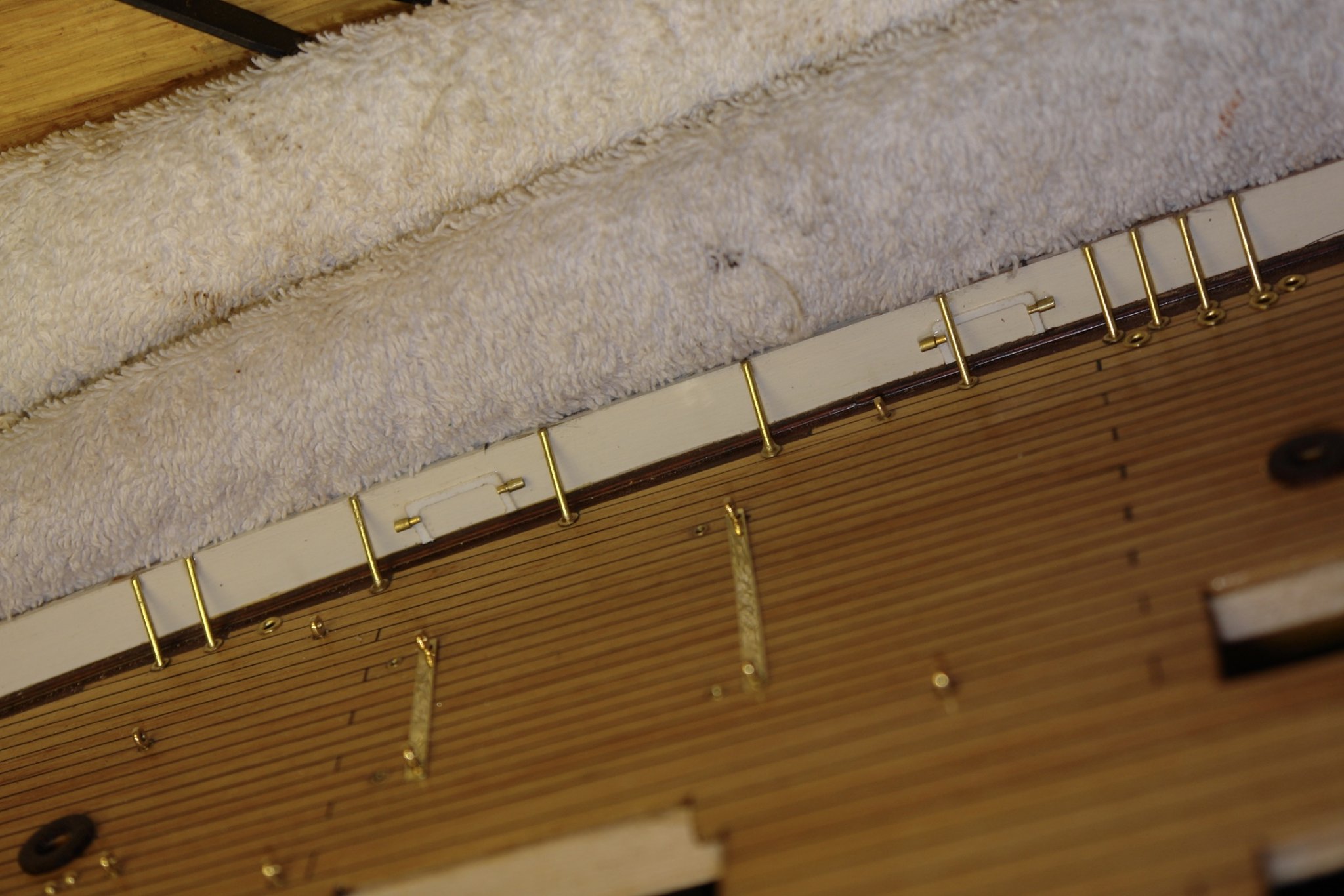
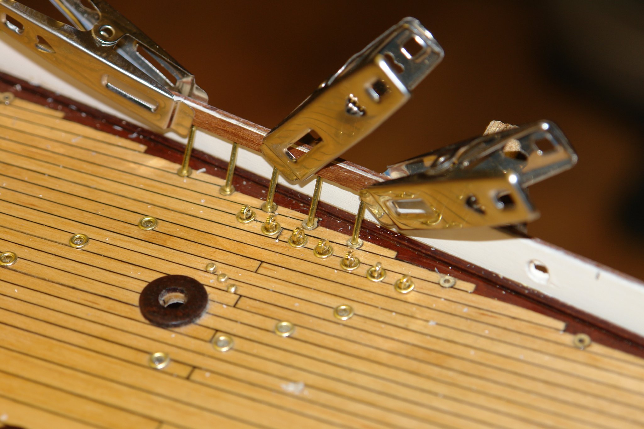
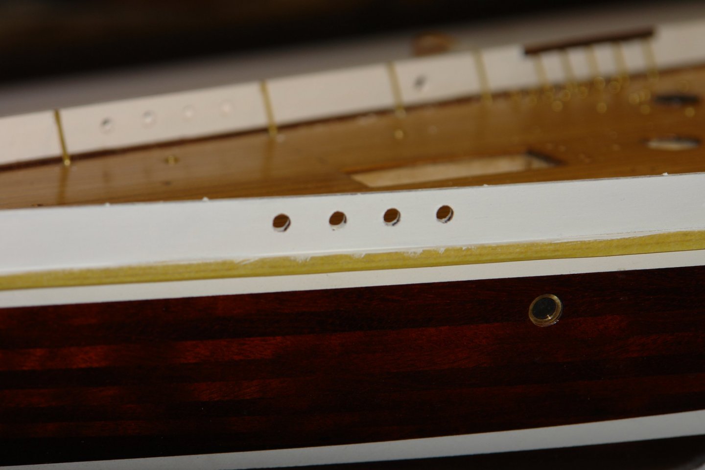
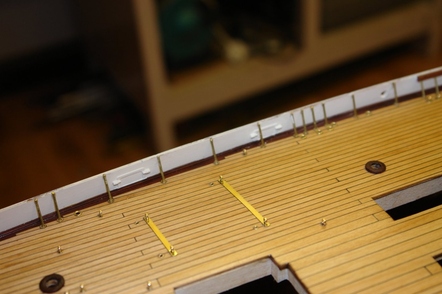
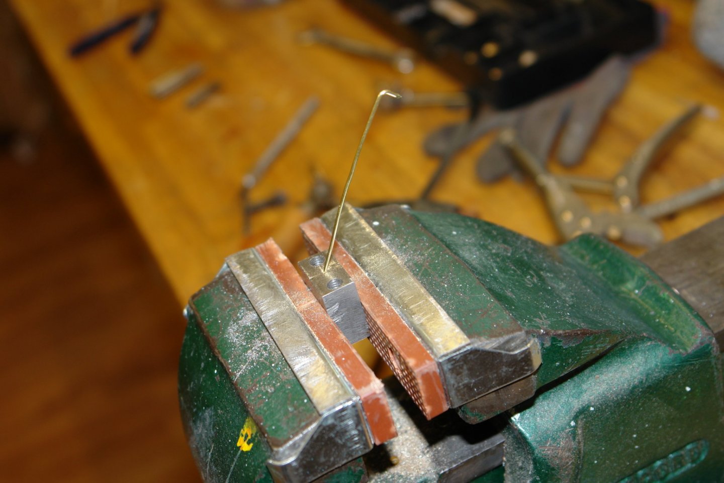
 I braved the freezing conditions in the workshop and finished off the struts. I hadn't finished the struts at the stern when I discovered the problem with the scuttle doors so diverted on to that. The struts at the stern sit at quite a shallow angle - seemingly more of an engineered trip hazard than practical bulwark reinforcement. Because of the angle I needed to open out the saw cut I had made to create a sharp bend for the spigot. After cutting the wire about 2/3 the way through I widened the cut with a triangular needle file before making a sharp bend. The next job is to mount the previously made reinforcing rings around the bulwark penetrations. I did a bit of white paint touching up in preparation - hence the masking tape on the rubbing strip. But the rings will have to wait until tomorrow, weather permitting.
-
Eberhard. Often during my sailing days I looked at gear and thought to myself that expediency had replaced good design. I think these days we are all used to design for mass production where the integration of features is normally well thought through. I suspect that in the case of low production run yachts some of the design is a bit "suck it and see". That said, the pivot is towards the top of the door (so that it closes by gravity) and while this means that the top of the door does move in towards the struts the degree of inward travel is limited. Yes Michael, in my case usually because the more complicated ones usually don't work.
-
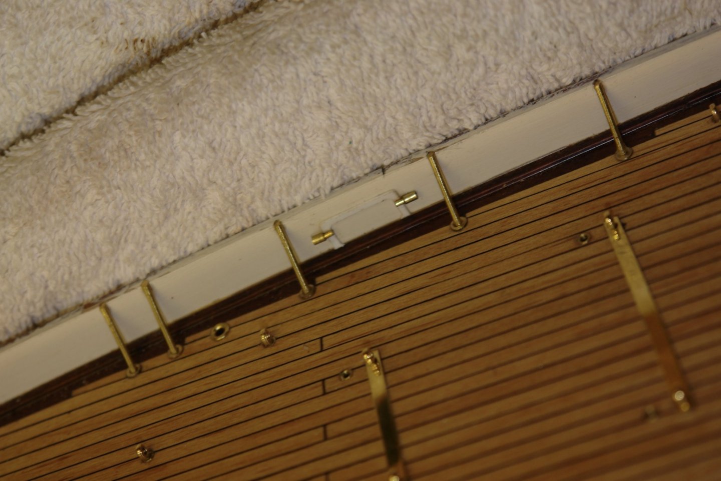
Druxey, John, Gary, Michael - thank you for dropping in and leaving your kind comments. In my eagerness to get on with the bulwark struts I had omitted to think about the build sequence. This led to the tricky task of inserting the simulated inner scuttle features (flanges and hinges). The following photo shows the detail I needed to create. I had previously made the door edge detail - covered in an earlier post. Now I had to glue the pieces on to inner bulwark, in some instances behind the struts. I glued the pieces on using 2 part epoxy to give me a little flexibility on positioning. I had made the hinges from wire and tube, both cut using simple jigs to get the correct lengths. The hinges were quite small. Once glued in place the doors looked quite realistic. Once painted they almost disappeared which is ok as they are not prominent on the original.


-
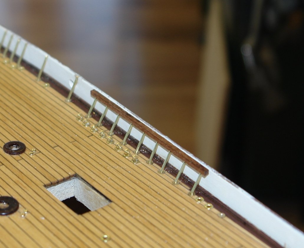
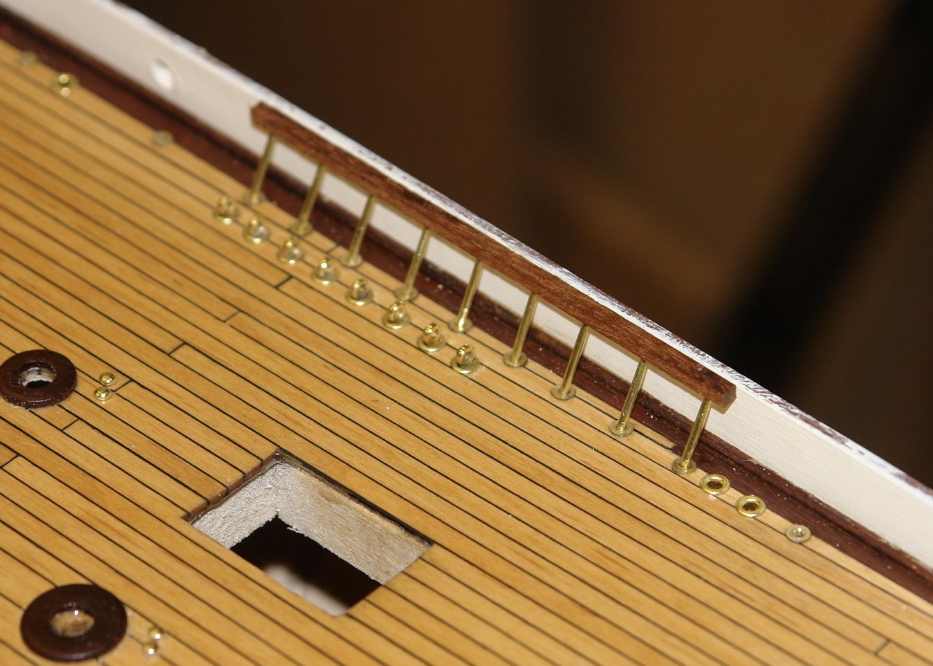
I have been plodding on with the bulwark struts. The full height ones are cut just over length on the model with side cut pliers. A notch is cut in the bulwark to take the upper end and then they are glued in place with CA. Finally the last few thou is taken off with a file until they are flush. I have 100 struts to do and am about 70% done. I should finish tomorrow.
-
Good progress Mark - as you know I use balsa filler blocks a lot. I have never had any problems with cracking of the overlaid planks.
-
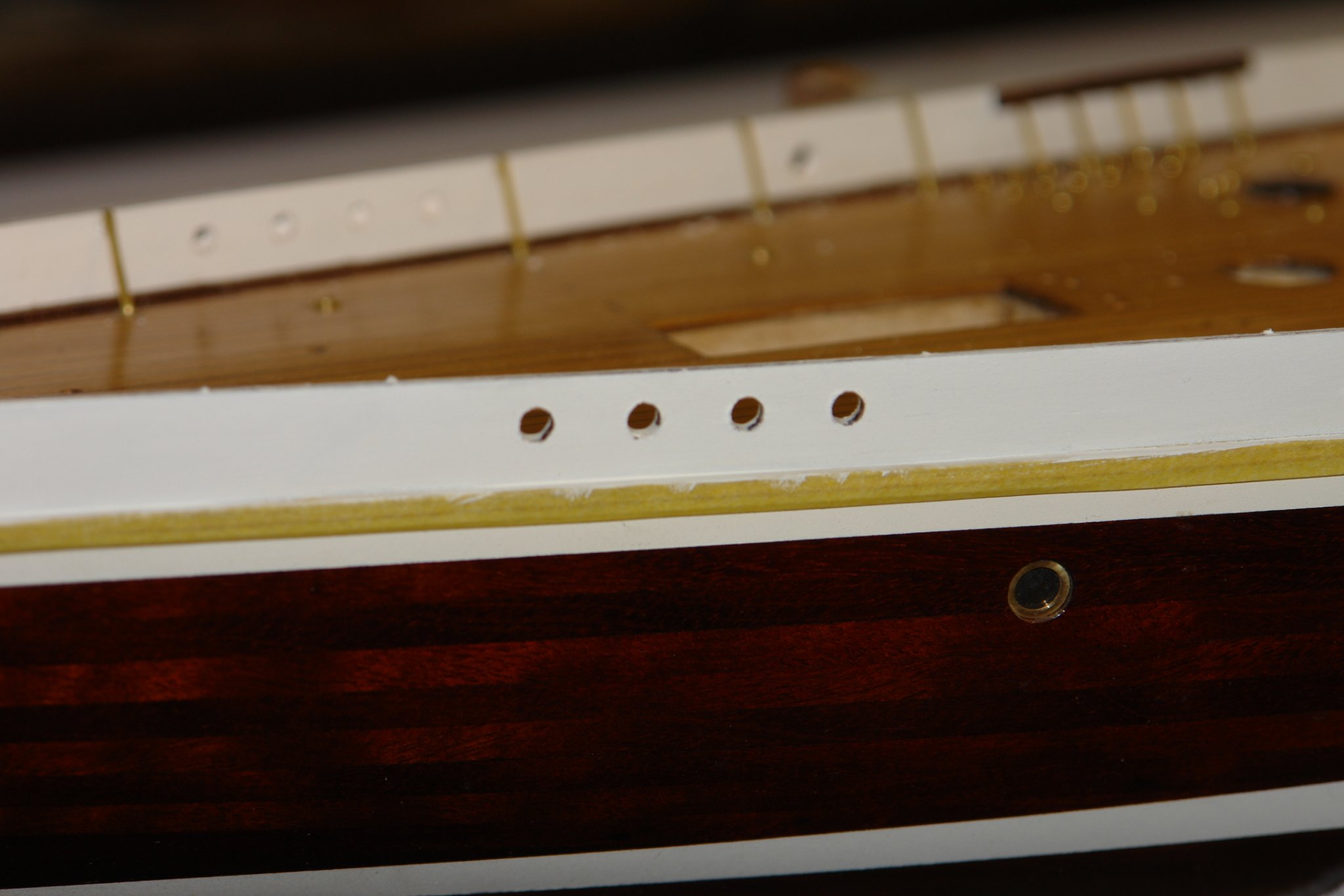
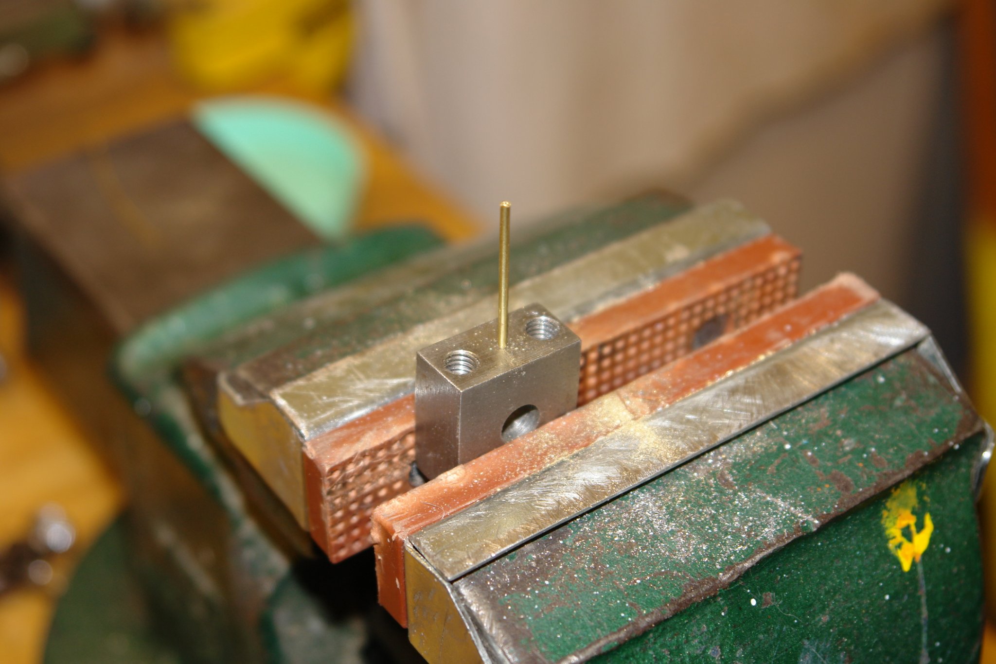
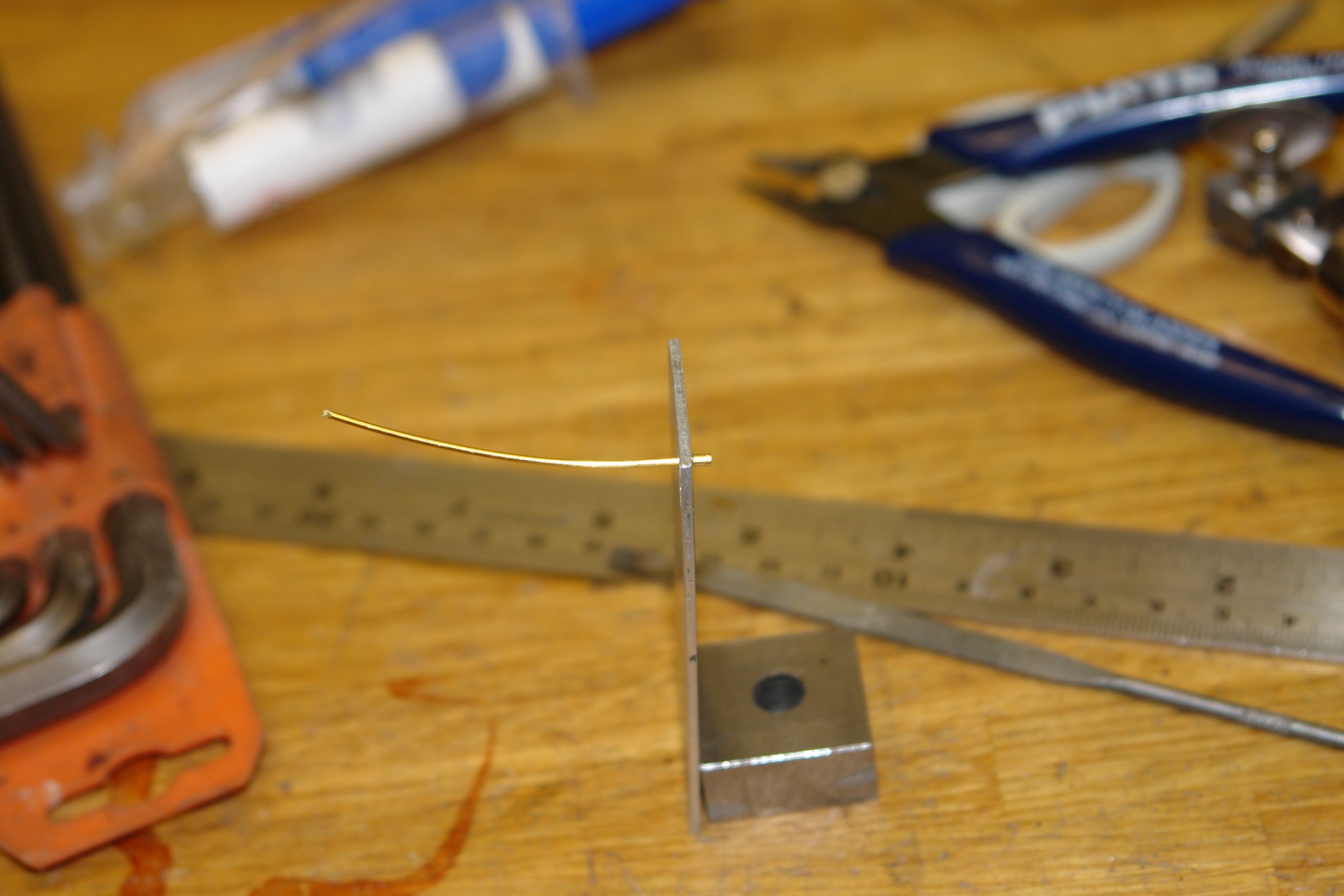
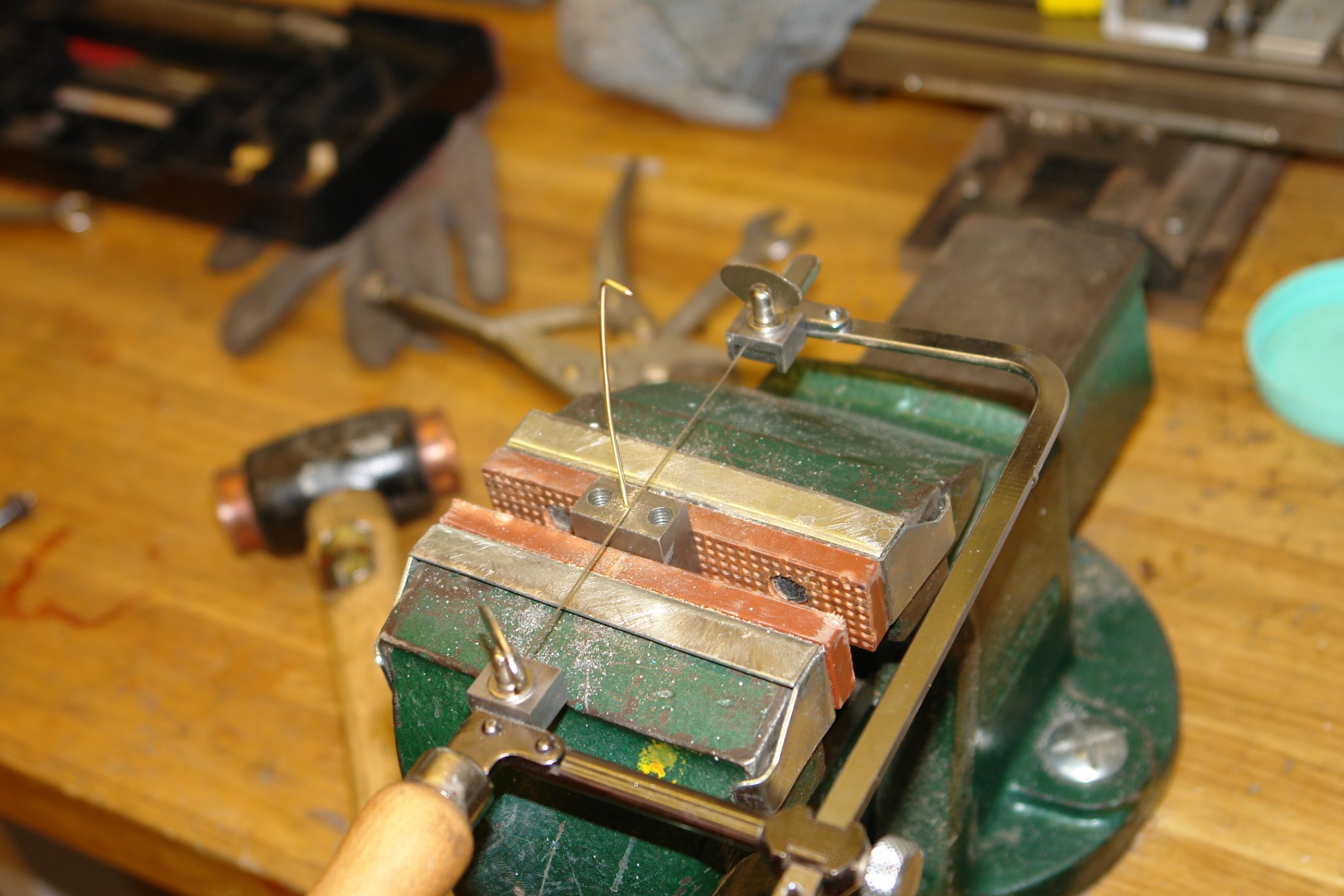
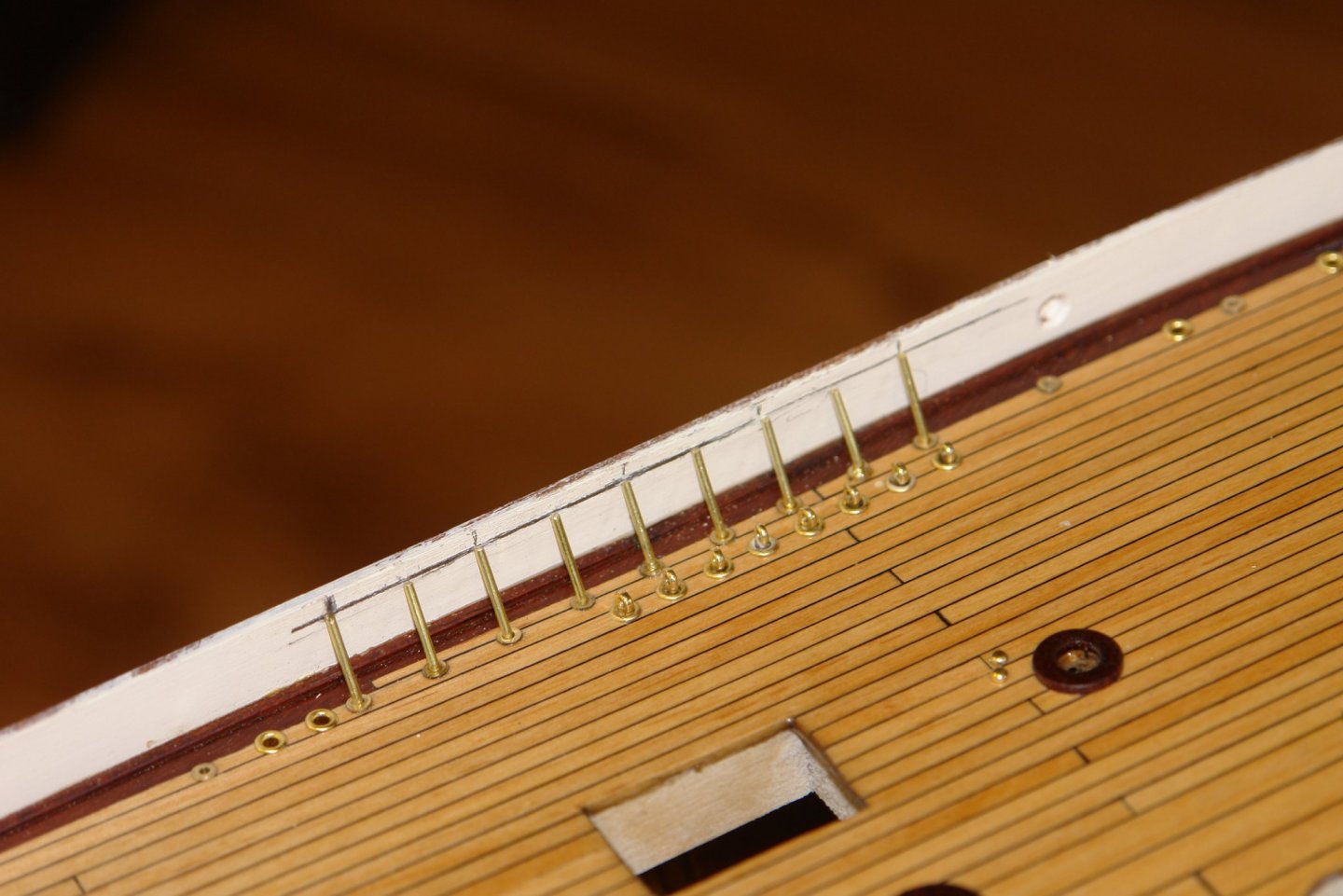
Greg, Pat, Keith - thank you for your comments and your continuing encouragement. I am still avoiding the pedestals for the deck cleats. So I made a start on the support struts for the bulwarks. They are steel in real life but for the model they will be brass. At the location where the shrouds attach to the rail the bulwark has a reinforcing plank. This sits under the capping rail and in consequence the support struts in this area are shorter and lean at an increased angle. The struts are made out of .050" soft brass wire rolled straight between blocks of wood. I first drilled a .100" deep x .050" diameter hole in a piece of scrap mild steel to take the wire and with the wire inserted in the steel I used a jewellers saw to cut about 2/3 of the way through it. I bent each wire by eye to fit. I marked out the position of the reinforcing plank and installed the struts accordingly. The reinforcing plank was then glued in position and clamped. This was repeated for the 4 locations where the shrouds attach to the bulwark rail.


-
Gary - one of the best bits about building classic yacht models is the admiring comments made by household visitors. I think you will get many. Your build speed was impressive and the resulting model is a fine execution of this kit. Well done. I look forward to seeing the picture of Endeavour in her display location.
-
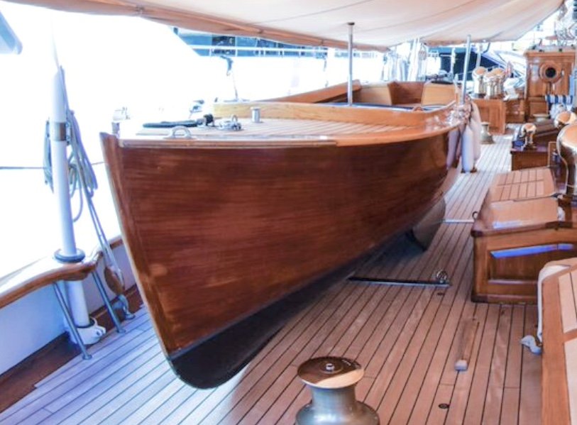
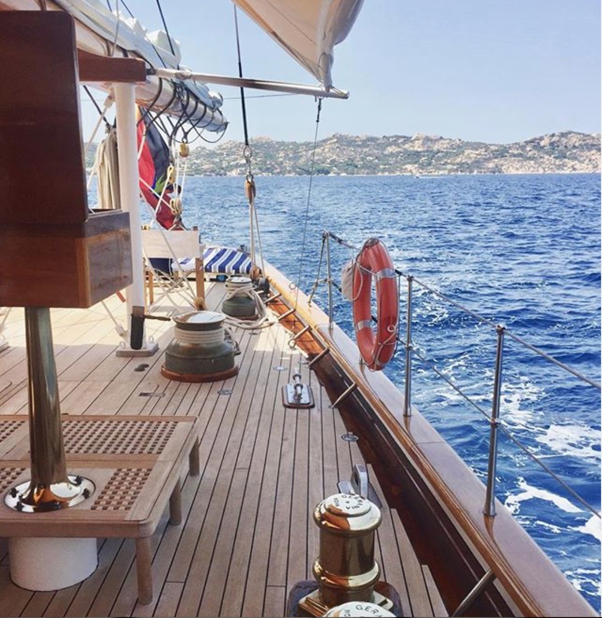
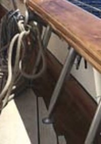
Deck looking lovely - I should have said this earlier and in fact it probably does not matter on the model. Sheets go round the winch a minimum of 3 times. If they go round only twice insufficient friction is generated to hold them in place as the tail is released from the cleat. A lesson I learned the hard way when the sheet pulled through my hand and took all the skin off my palm and upper part of my fingers, not much fun when medical facilities are many hours away. The other lesson was always wear sailing gloves.
-
Gary - all very nice - but!!! - the sheets normally go round the winches in a clockwise direction. The winches turning clockwise to wind in the sheets in.
-
A very attractive model - excellent work.
-
All looking very nice Gary. The problem with making such quick progress is that you have to start thinking about the next build sooner.
-
Hi Paul - yes I agree B****y cold in the shed. I bet the cat had more sense.
-
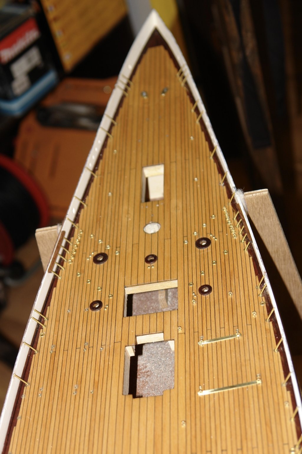
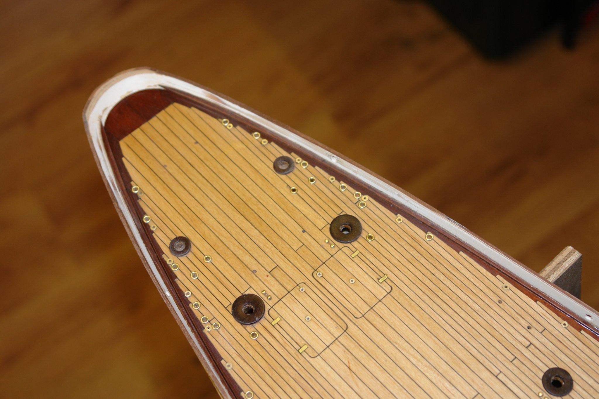
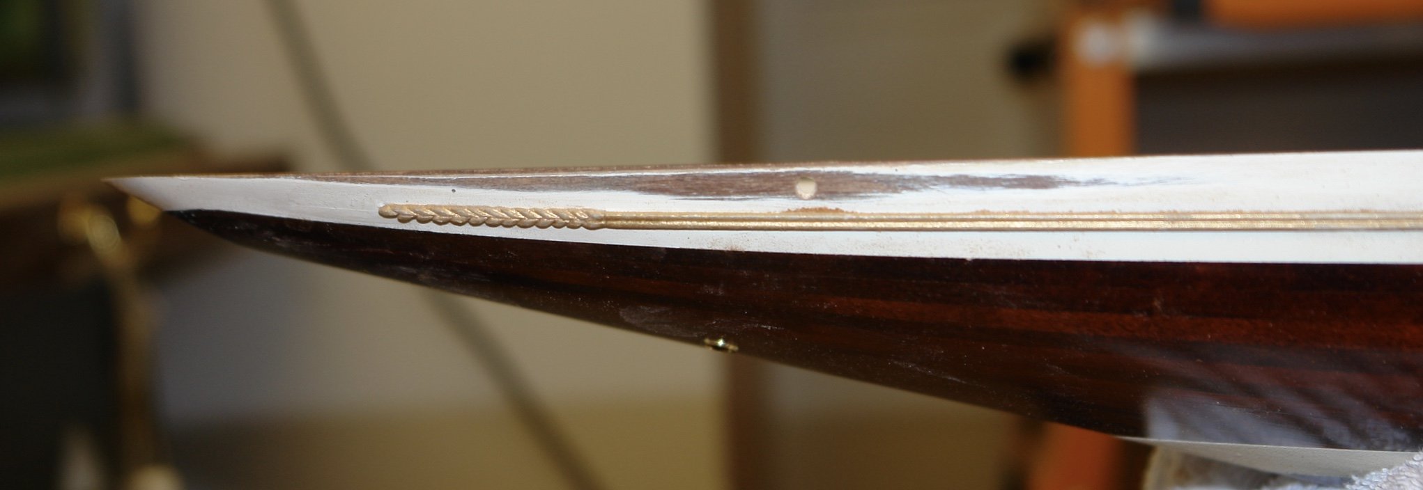
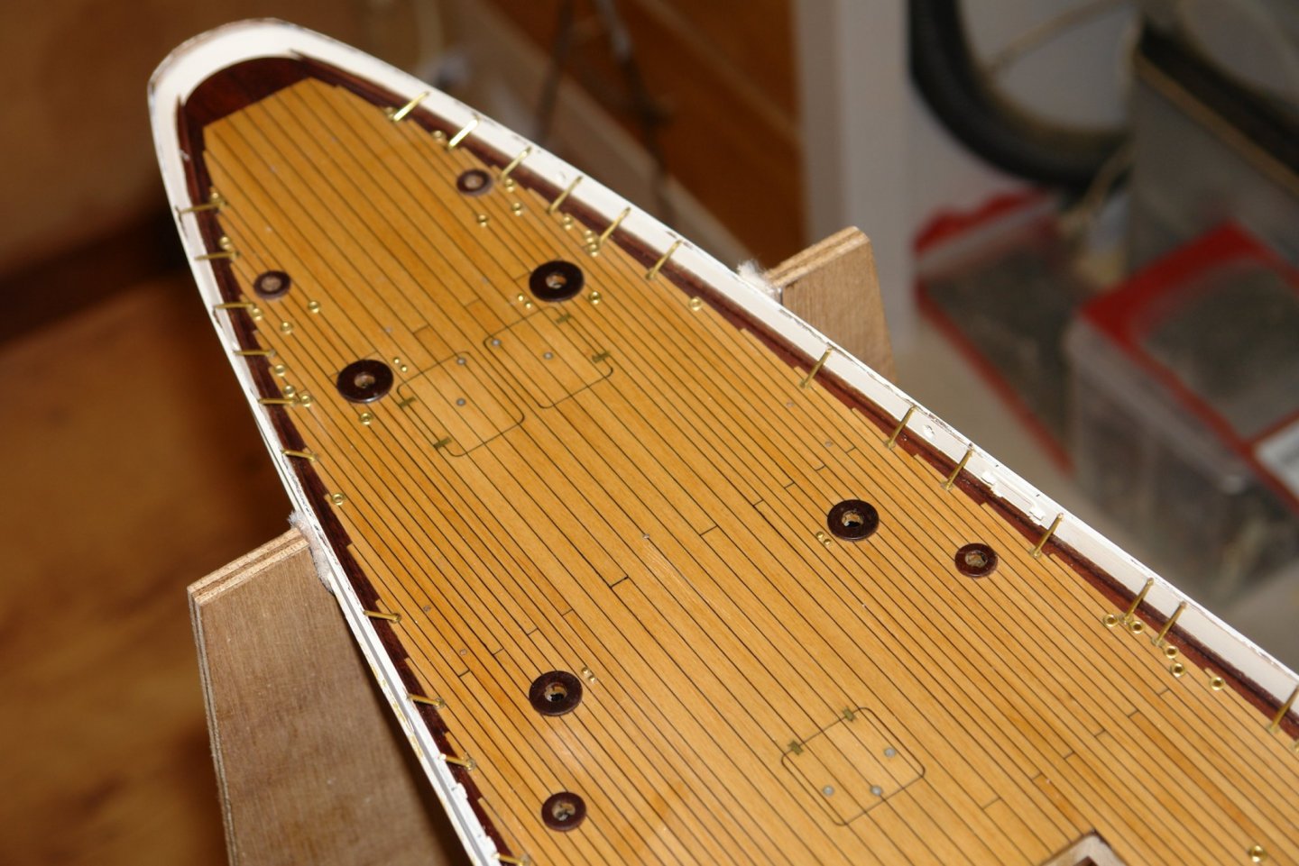
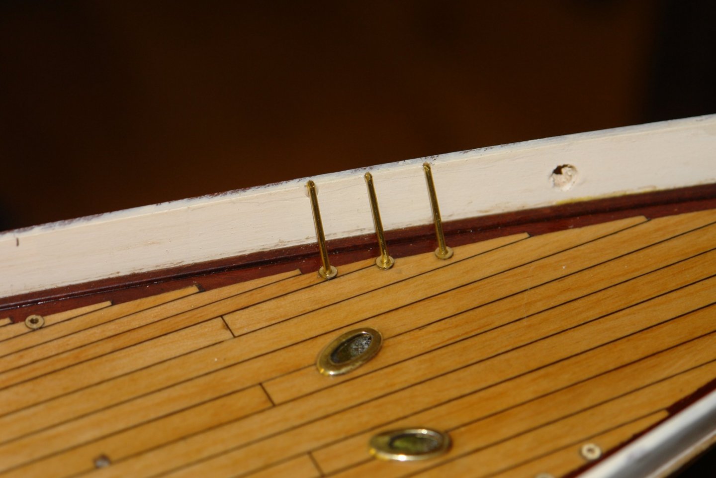
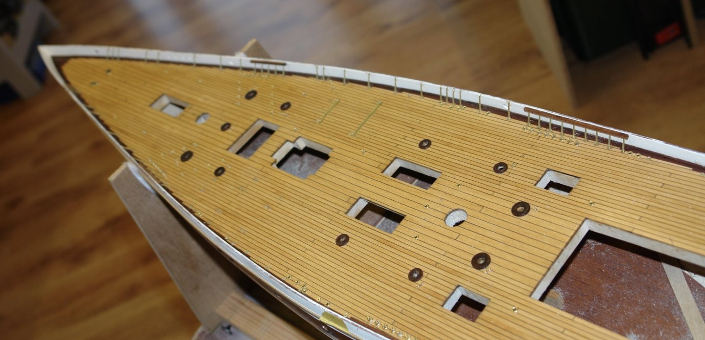
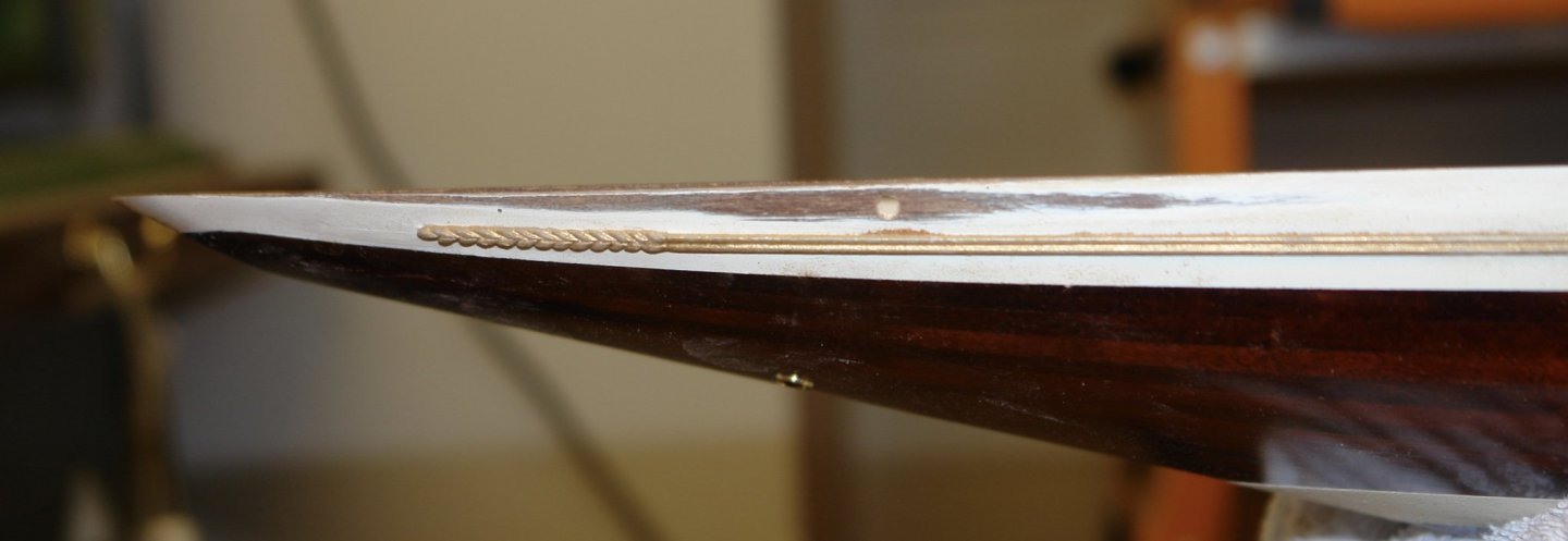
I am fighting the urge to do another small fitting production run - namely making the pedestals for the deck cleats. Finding anything to distract me from the task seems to be the imperative of the day. For a while I have been looking at what to me seemed to be an enormous dip in the line of the bulwark at the stern - the product of overly aggressive sanding. I decided to fix it. I started by taking an A4 sized sheet of sheet MDF and laying it over the stern. Then with a set of feeler gauges I measured the dip (gap between MDF and the Bulwark). It turned out to be .025" on one side and .020" on the other. It is surprising how the eye detects and the mind magnifies such errors. The dip extended over a length of about 5 inches and tapered from the measured dimensions in the centre to nothing at the ends. To repair the problem I cut mahogany strips of .030 thickness and attached them to the top of the bulwarks with PVA glue. I then applied weights to hold the strips down while the glue dried. The strips were over wide to allow for the curvature of the bulwark and once glued had to be sanded back on the edges to conform with the bulwark profile. Careful sanding was required and inevitably this led to the sanding away of some of the previously completed paintwork - as always in this hobby one job leads to another. Having sanded the edges I glued an A4 sheet of 120 grit sandpaper to the previously mentioned sheet of MDF and then used this to sand back the top edge and establish a much more pleasing top line. In the next photo you can see the repair. The residual paint just about lets you see the old and new top lines. The final shape is much more pleasing - or this at least this is what my imagination tells me.


-
Michael -thank you - that is what I assumed you meant and is what I will experiment with.
-
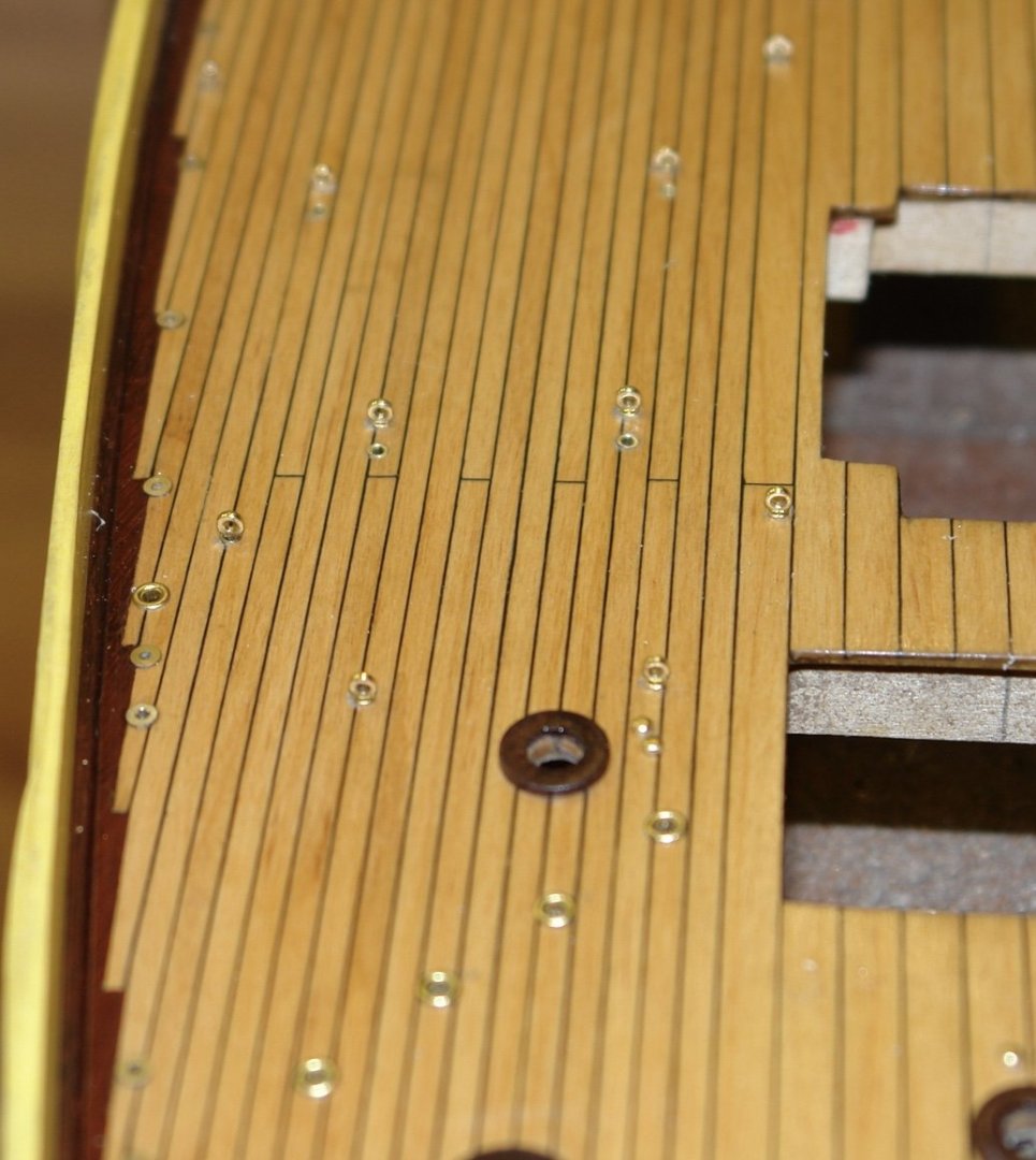
Michael - I will add it to the experimentation list. I did do a bit of sanded deck wood filling around the hawse pipe holes (albeit this area was hidden under the brass rubbing rings). I did find that the filler was somewhat darker than the wood but this may have been caused by the PVA.
-
Of course in my case I am either too thick or too old to contemplate expending what little precious time I have left learning CAD - although I do admire Vaddoc's skills. When I was taught drawing I seem to remember the pinnacle of skill was sanding the correct wedge on the end of the pencil - .012" thick for scheme drawings and .025" thick for detail drawings. Life was easier in those days.
-
Excellent work Gary. I spent part of today trying to make .080" OD eyebolts so I have every sympathy with your approach.
-
Julie - I tried a number of cards - basically looking for the least fibrous and smoothest surfaced I could find. I then experimented with the best and found this card produced the optimum results.
-
Gary - I thought the set of steps were one of the more unusual workshop tools I have seen on MSW. Well done on the sails.
-
Phil, I do admire folks who have the patience and dexterity to take on miniature carvings. Well done.
-
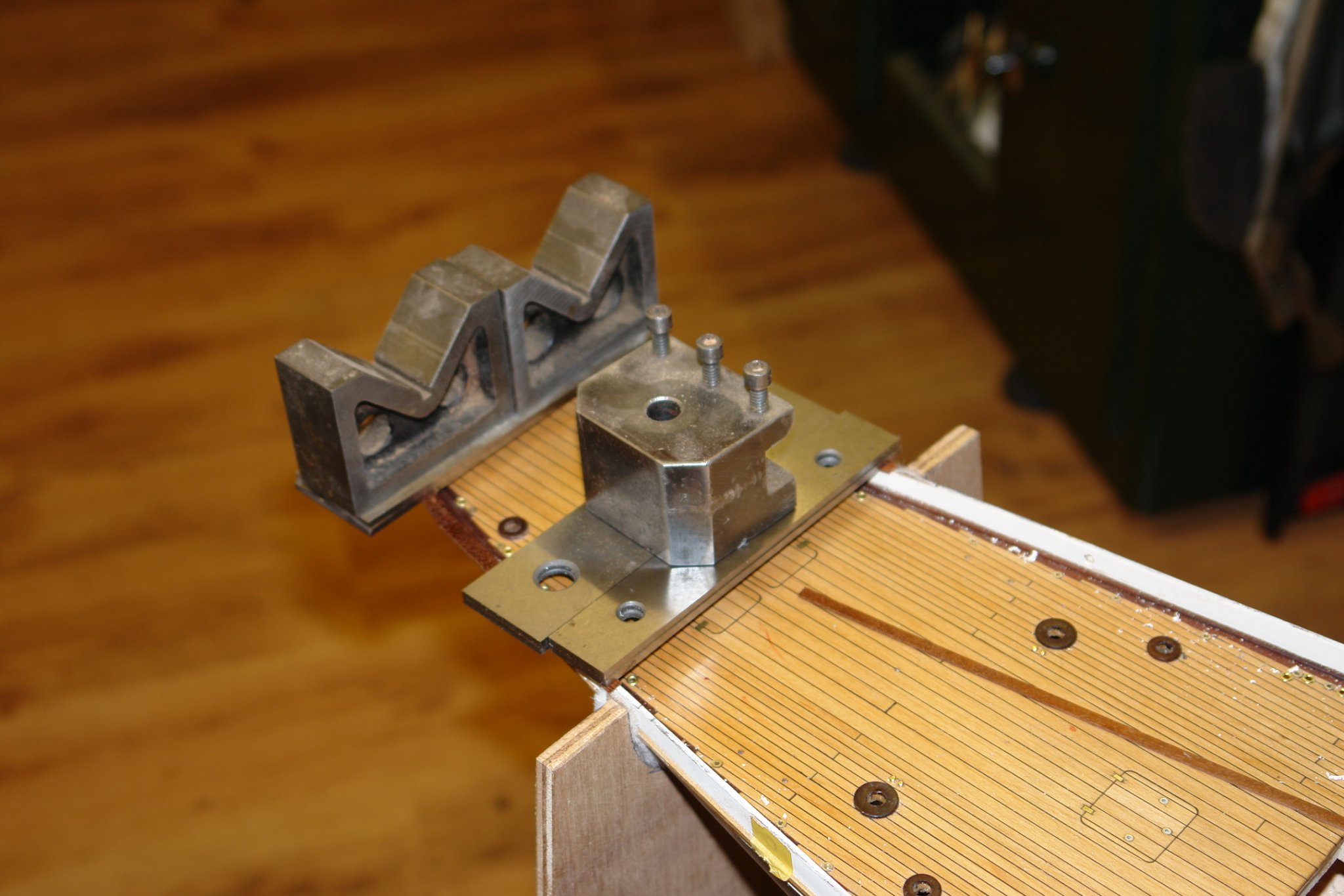
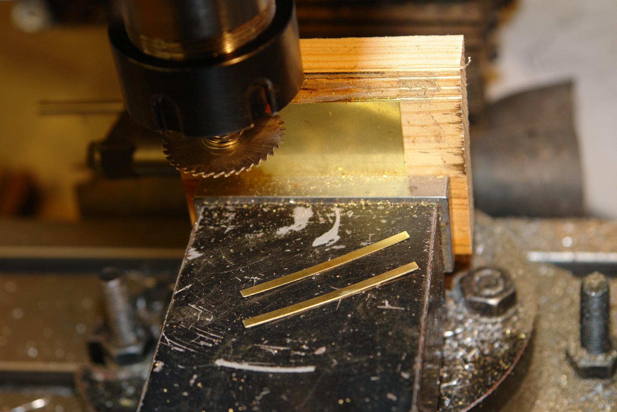
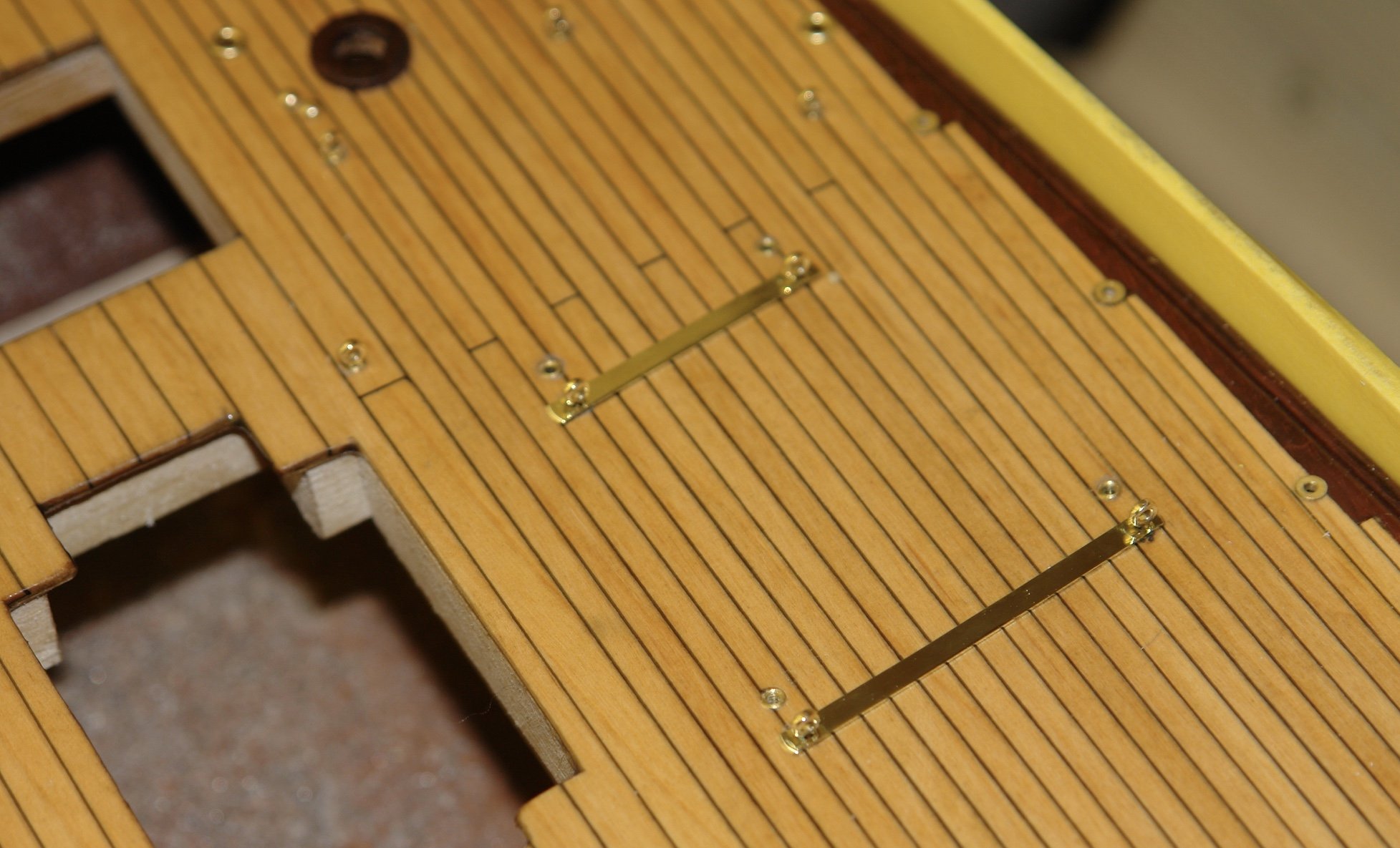
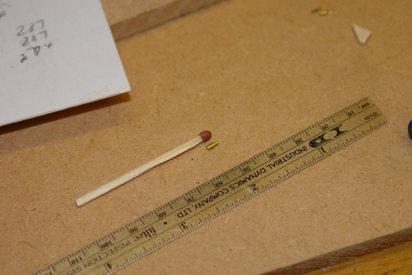
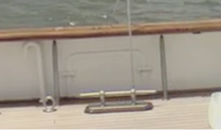
Druxey, Gary, Pat, John, Mark, GL, Paul. Thank you all for your comments, and many thanks to all those that have liked my build. I have had an unproductive few days - so only a little progress to report. The tender sits on the deck on protective metal strips. At the end of each strip is an eyebolt and a number of additional eyebolts form the anchor points for the boat lashings. The deck bosses for the boat lashing points are smaller than those for the rigging eyebolts. Narrow necked eyebolts are required for these lashing points. The metal strips were cut from .015" brass sheet. They needed to be .080" wide. They could have easily been cut with tin snips (or even a craft knife) but I decided cutting them on the mill would produce a better result. I cut strips of the required width using a slitting saw with the brass sheet mounted vertically in the vice and supported by a piece of scrap wood. The strips were then cut to length, the ends profiled and holes drilled to match the deck holes. Finally the strips were polished and mounted on the deck.