Cathead
-
Posts
3,487 -
Joined
-
Last visited
Content Type
Profiles
Forums
Gallery
Events
Everything posted by Cathead
-

Barncave Shipyard by mbp521 - Scale 1:1
Cathead replied to mbp521's topic in Non-ship/categorised builds
Looks beautiful! I thought of a question about your mini-split. Are you planning to leave it on all the time to maintain some consistent temperature and humidity, or only turn it on when you plan to be in there and leave the room to the elements otherwise? Seems a tough tradeoff between too much energy use on one hand but potentially problematic swings in environmental conditions on the other. Although we like our mini-splits, one thing that does annoy us is that they have a relatively narrow range of temperature settings that doesn't go below 59ºF. So for example, if we're traveling in winter and just want to keep pipes from freezing, we'd rather set the house at, say, 45º; 59º is a waste of energy. It's a bit easier in summer when you can set temps in the 80s. So I was wondering what temperature range your unit has and how you plan to handle that dilemma. -
They must be Gary Larson cows; in the Far Side they're always standing around and walking upright.
-
Barncave Shipyard by mbp521 - Scale 1:1
Cathead replied to mbp521's topic in Non-ship/categorised builds
Mini-splits are great, years ago we removed our furnace and installed a couple instead. They're more energy-efficient and eliminate using all that ductwork that can get dirty/dusty/moldy. Won't work for every house design (e.g. if you have lots of isolated rooms) but we have a fairly open floor plan that allows air to circulate (installing a few ceiling fans helps with this). We heat primarily with wood but the units provide a backup, and are far better than window A/C in the summer. Plus it's easier to close off rooms we don't want to heat/cool as much (such as spare bedrooms) by just shutting the door, rather than closing a vent but still having all that hot/cold air blown through ductwork to a dead end. Definitely a great choice for a setting like Brian's. -
I'm no expert, but it's logical that adding moisture to a fiber product causes it to swell. And it's likely that different glues/applications would cause the line to react and swell differently, so it's not clear how manufacturers could account for that in a single consistent measurement. In other words, the manufacturer's dry measurement can be accurately measured and standardized, but the wet measurement depends on what the individual modeler does. So if the change concerns you, perhaps the best solution is to account for a certain level of expansion when you purchase line?
-
Barncave Shipyard by mbp521 - Scale 1:1
Cathead replied to mbp521's topic in Non-ship/categorised builds
Fantastic project! And here I am looking forward to expanding from a 2'x4' workbench to a corner of a small spare bedroom! This looks really cool and you know I respect DIY projects. Will be fun to see it come together, and I love the exterior aesthetic already.- 70 replies
-
- 10
-

-

-
Edit: Oops, meant to post this in the Jokes thread. Oh well, this could function as a dodgy solution, too! I'm going to cross-post it where I meant to, anyway, sorry if you end up reading this twice. Real conversation between my wife and I recently, edited for clarity and brevity. Background context is that we log and mill lumber on our rural property and are preparing for another round of milling later this week. We both also love puns. Wife: Are you going to cut up that basswood that fell across the creek? Me: It'd make sense, it's good model wood. Wife: You could also go to the pond and catch some bass. Can you compress fish into building material like you can recycled plastic lumber? Me: That kind of basswood would be even better for scale modeling!
- 227 replies
-
- 11
-

-
-
Glad to see you're still working on this!
-
Timber-framed outdoor kitchen - Cathead - 1:1 scale
Cathead replied to Cathead's topic in Non-ship/categorised builds
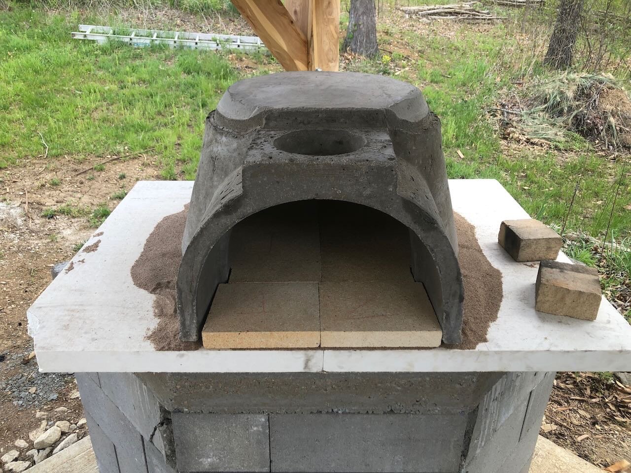
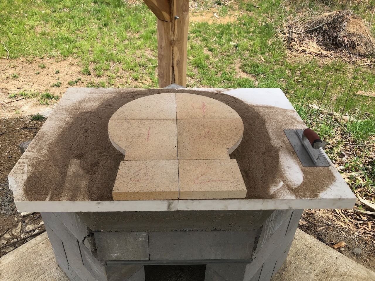
After letting the hearth cure for a few weeks, we took the exciting next step of installed the oven dome itself. Following the instructions, we first placed a layer of 2" ceramic insulation board over the hearth, spread a layer of sand on that, then carefully arranged the firebrick cooking floor to be level and centered. Then, with the help of some friends, we carried the ~200 lb oven dome itself over and carefully placed it over the floor. The next step will be to cut the insulation board down to match the outer shape of the dome, start installing the chimney, and start wrapping the dome with ceramic insulation blanket. The whole thing will eventually be covered in stucco to seal the surface. But it's actually looking like an oven!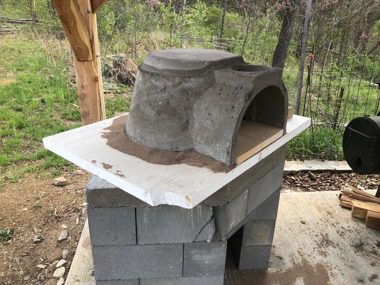
- 131 replies
-
- 13
-
-
Yeah...I really, really like that color scheme. I so wish this had come out a few years ago.
- 80 replies
-
- 4
-
-
- Grecian
- Vanguard Models
- (and 3 more)
-
Nice to see you back! I've simulated tar paper roofing before using strips of masking tape laid over thin wood glue. It has a nice rough texture, holds up well, is much easier to apply than silkspan or tissue, and is very affordable. Seems like it would work especially well in 1:48. Easy to give it a try on some scrap wood to see what you think.
- 157 replies
-
- 1
-
-
- chaperon
- Model Shipways
- (and 1 more)
-
Dust masks and respirators.
Cathead replied to Bill Hudson's topic in Modeling tools and Workshop Equipment
Those California labels are a classic case of how over-regulation or hyper-concern run amok can backfire. I'm sure it meant well at first, but saturating the market with fear-mongering just leads to people tuning out, including more legitimate concerns. Especially when they can see for themselves that the risk isn't really there in normal use, or is minor compared to other risks. For example, touching a table saw might expose you to a California carcinogen, but the risk is minuscule compared to that of using the table saw, or especially using the table saw wearing the sorts of gloves you'd need to protect you from the carcinogenic metal. So the label at best does no good, and at worse numbs people to legitimate warning labels and leads to distrust of regulators. -
Dust masks and respirators.
Cathead replied to Bill Hudson's topic in Modeling tools and Workshop Equipment
Any natural material can be unsafe if consumed or used incorrectly! Dihydrogen monoxide is a great example; utterly benign in sensible quantities but too much will kill you in minutes. One of things I love about modeling in wood is that it does require handling fewer nasty materials, at least the way I do it. -
Thanks for sharing!
-
Welcome from a fellow Missourian!
-
Timber-framed outdoor kitchen - Cathead - 1:1 scale
Cathead replied to Cathead's topic in Non-ship/categorised builds
Brian, don't feel bad, I've been without a shipyard for over a year now as our DIY renovation of a spare bedroom proceeds at a glacial pace. That's another thing I hope will be back in operation by later this spring. -
Timber-framed outdoor kitchen - Cathead - 1:1 scale
Cathead replied to Cathead's topic in Non-ship/categorised builds
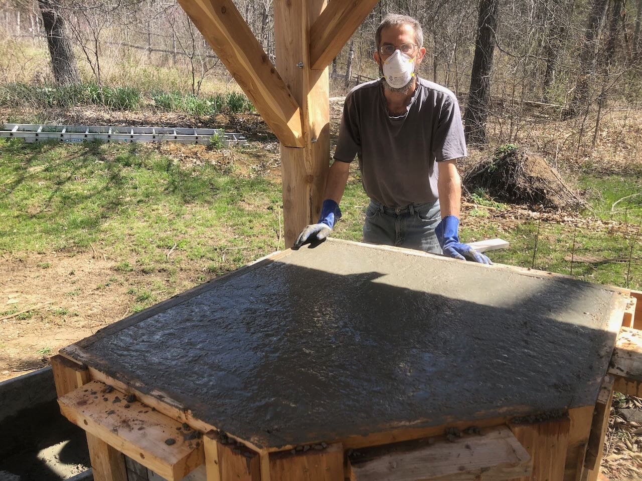
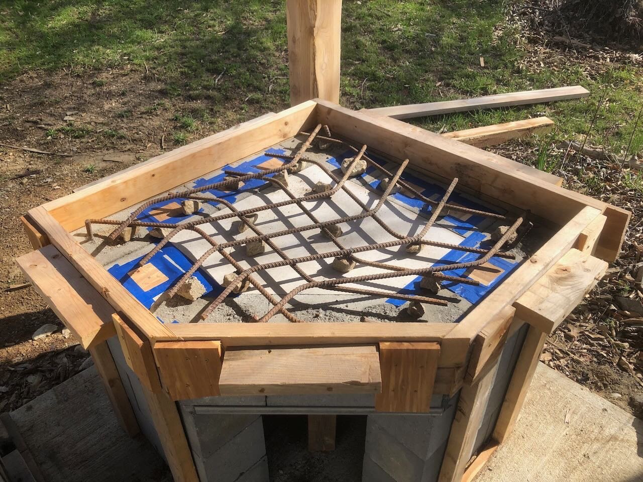
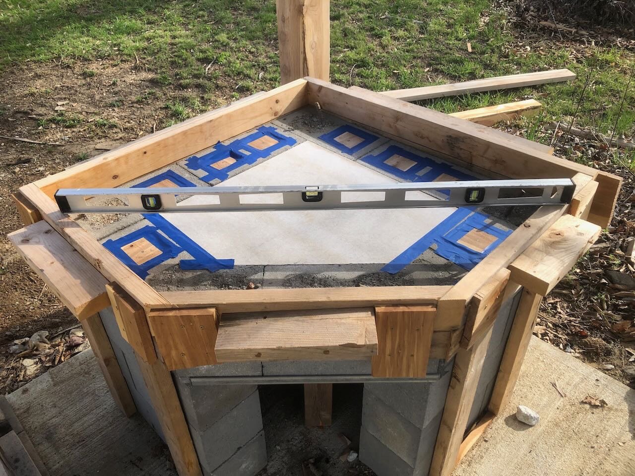
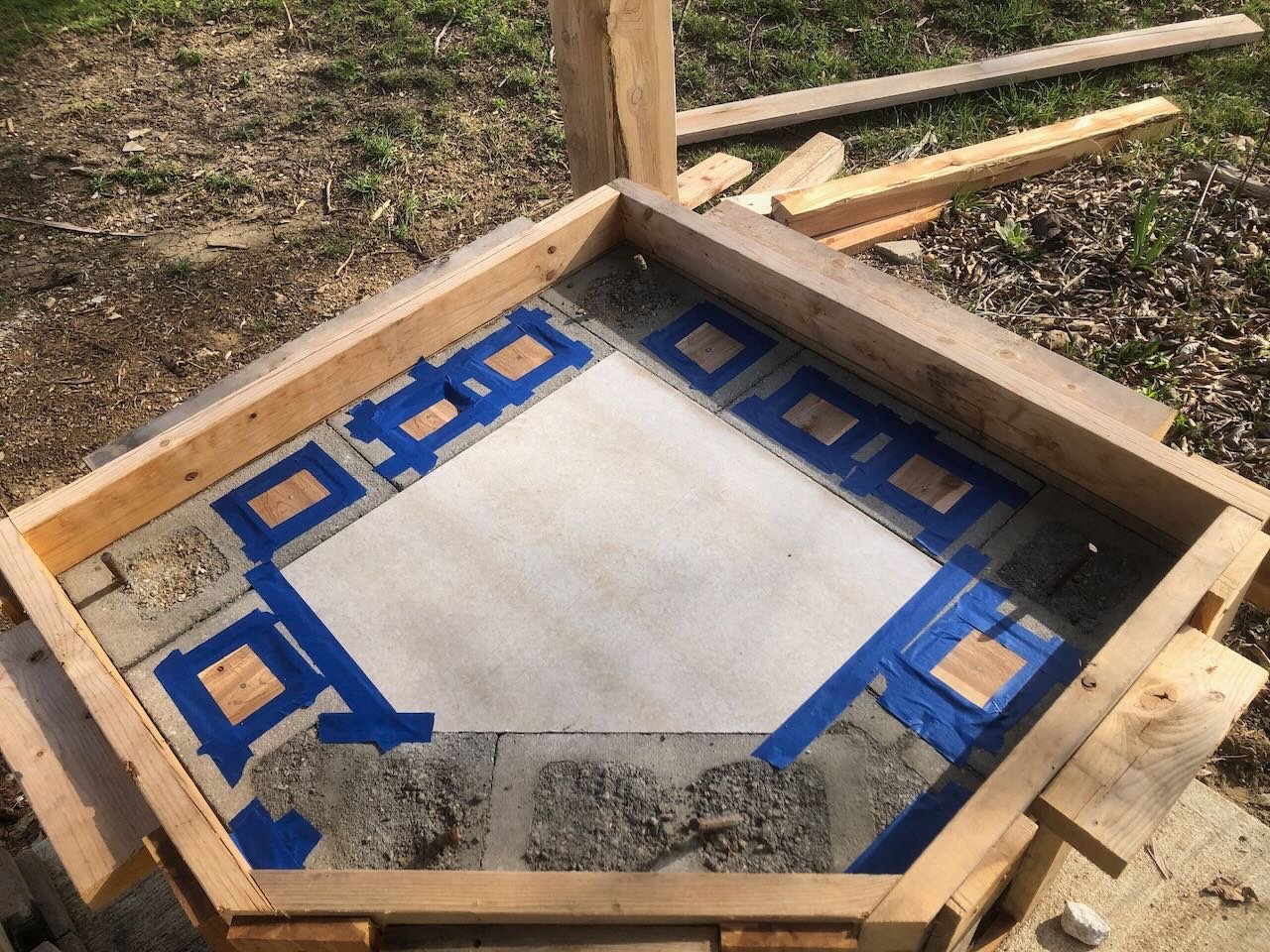
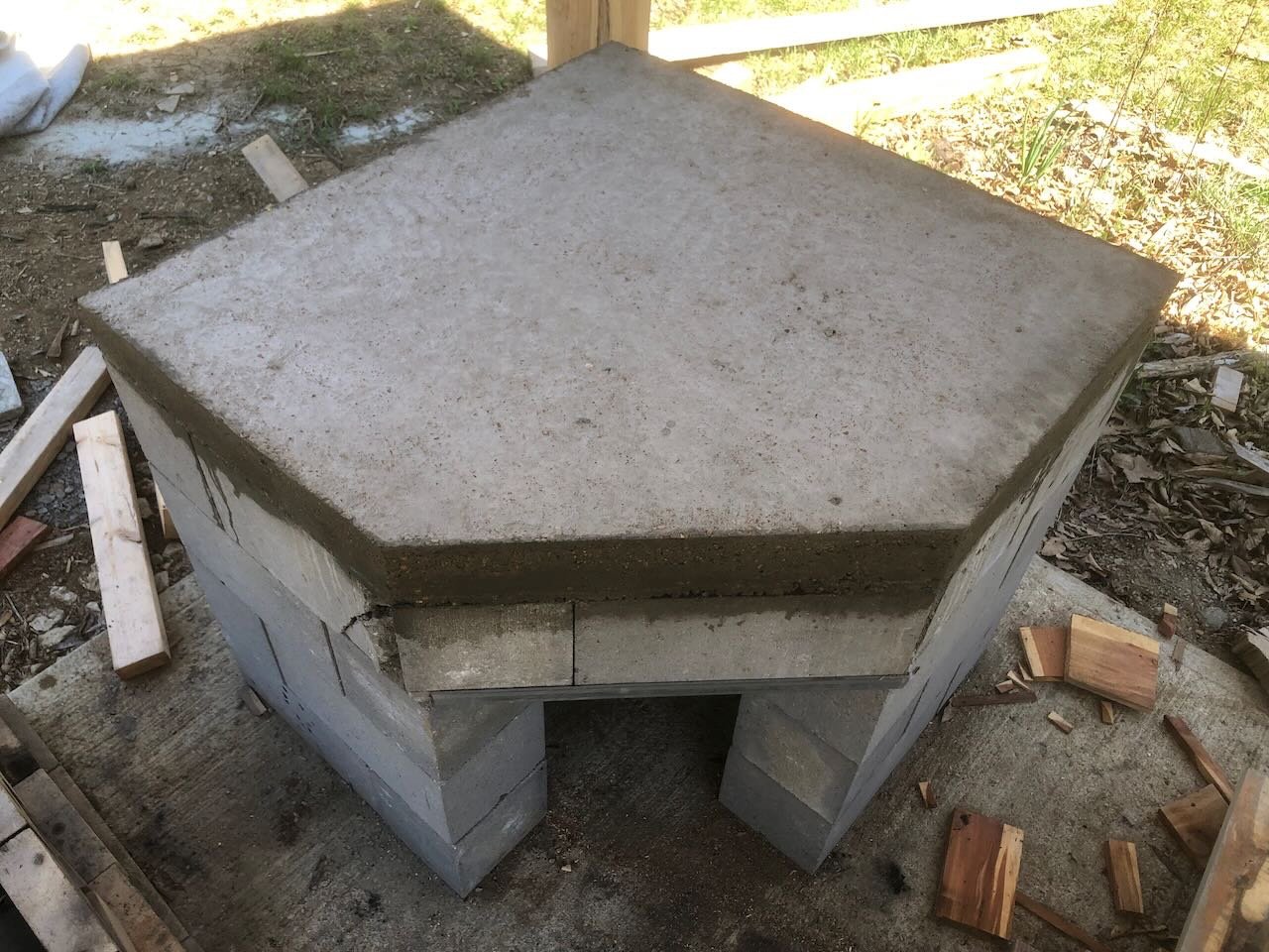
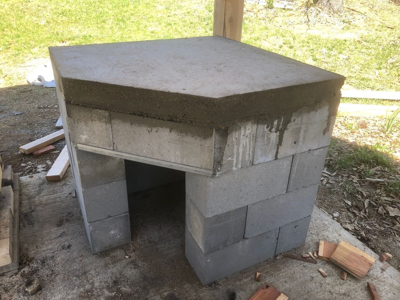
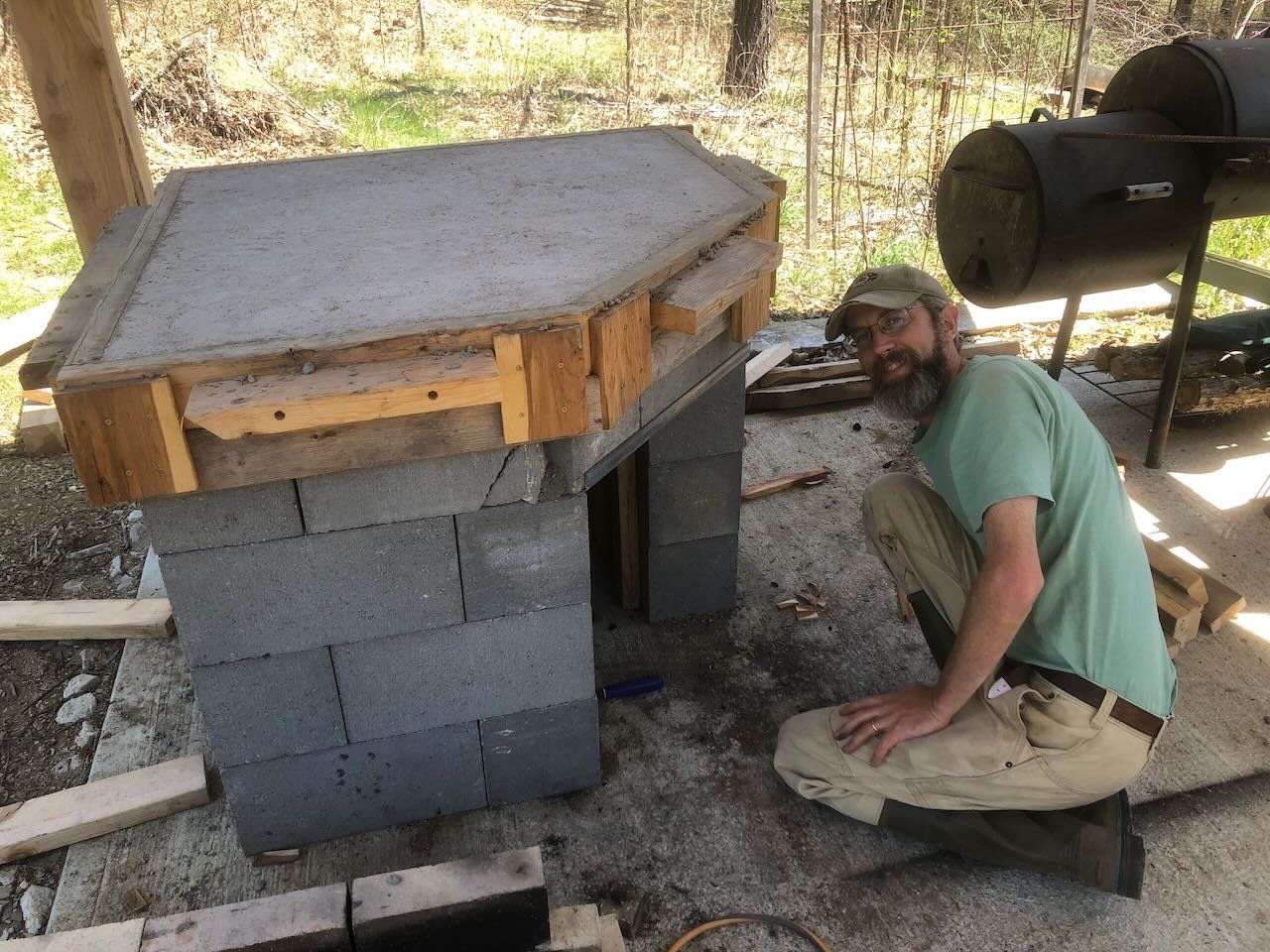
A major milestone! This week was the first since fall that we had warm enough, consistent enough weather to pour the concrete hearth that sits atop the foundation. On Monday morning, we took a break from other work to mix and pour the 6.5 bags of concrete required. As a reminder, here's how the foundation has sat all winter waiting for this moment: First I cut a piece of backer board to fit snugly in the opening, and taped all the remaining seams: I then re-checked that everything was level and adjusted the supports as needed (very little was required, it was quite tight and stable): Then a network of rebar was laid and wired together to strengthen the concrete. These were salvaged from a dump pile on our farm that pre-dates us; they were the perfect length for this job! Finally we started mixing the concrete by hand and shoveling it in. When we reached full, I compacted the mix and planed the surface smooth. Here I am with the finished surface, still wearing my mask to keep out the concrete dust since it's a pain to take on and off with rubber gloves on. I was thrilled to finally get that thing off, they give me headaches. At this point, we let the concrete cure for a couple days, moistening the surface occasionally. By this afternoon, it was time to remove the wooden forms beneath and around the hearth. I started by knocking and prying away the vertical supports on the outside and inside of the structure: And then disassembled the screwed-together form itself, revealing the hearth. We wet the newly exposed edges just in case a bit more moisture was needed now that they were exposed to air. We'll let this cure a while longer before taking the next step, but this is major progress! We have a busy couple weeks coming up, which is convenient in this sense, then it'll be time to start assembling the oven itself atop this surface. Just a reminder, the entire outer surface of this structure will be sealed with stucco, so it doesn't matter what the edge and seams look like (of the blocks or the hearth). Thanks for looking in. Hopefully updates will start coming more regularly from now on!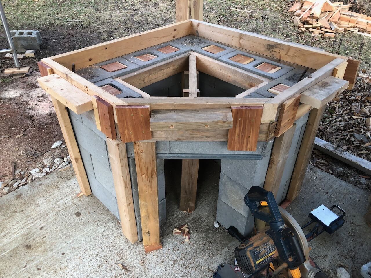
- 131 replies
-
- 11
-
-
Dave, I just stumbled across your log, which shows wonderful workmanship. I can't wait to see how the masts and rigging progress. I'm also sending you a PM since we appear to live very close to one another!
- 53 replies
-
- 1
-
-
- Speedy
- Vanguard Models
- (and 1 more)
-
Thanks for the update! Lots you're dealing with, glad you're coming out ok on the other side. Those are some tricky hull shapes for sure.
-
@MrBlueJacket Thanks for reading. As a self-employed small businessperson myself, I recognize how hard it is to please everyone and to take criticism (whether justified or not) of something you've sunk your soul into. The new larger-scale Cairo sounds like a fantastic project that will be far more likely to do justice to this amazing vessel. I look forward to seeing how that develops. Especially since I think interior cutaways are an underused niche in kit-making.
- 113 replies
-
- 8
-
-
-
- Cairo
- BlueJacket Shipcrafters
- (and 1 more)
-
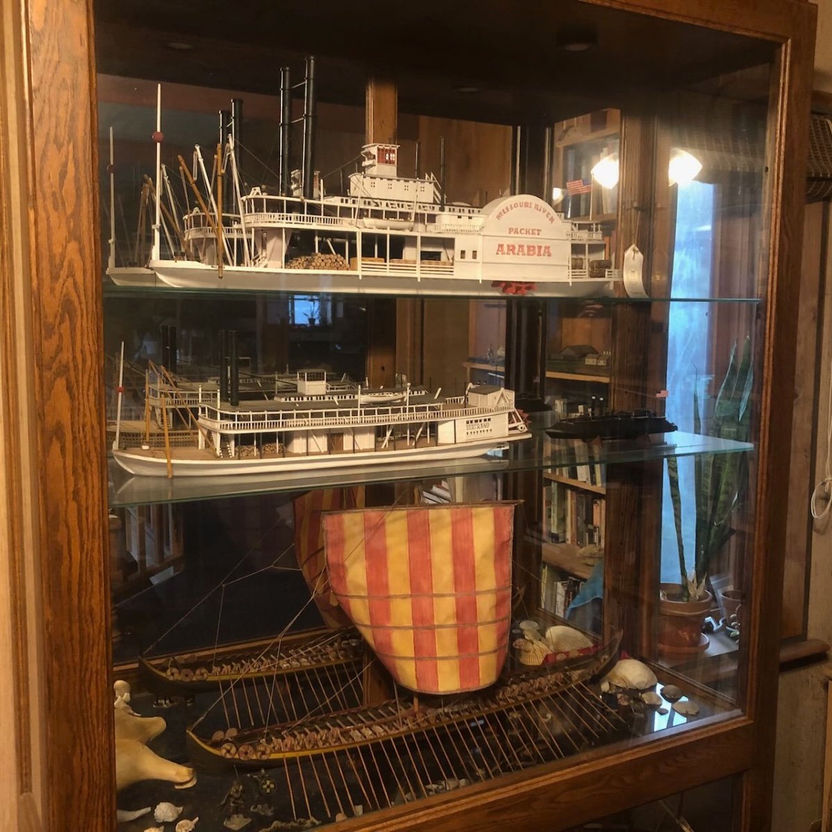
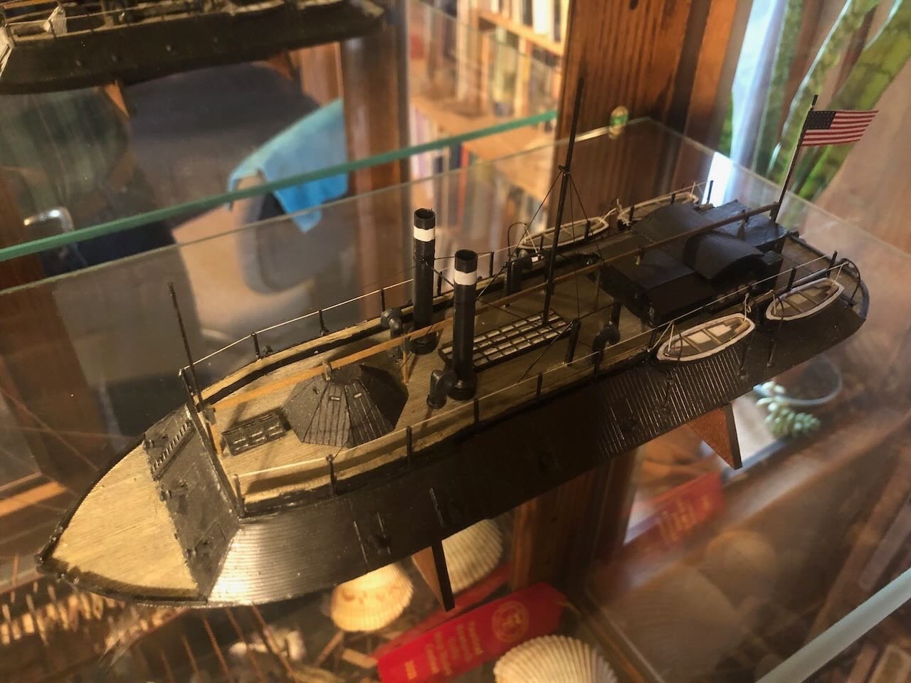
Thanks, Brian & others, for the feedback and uplifting comments. Yeah, I hadn't conceptualized how the dark coloration would interact with the other two white vessels. It really hides the model. Not that that's necessarily a bad thing. I'm pretty sure I know what the next project will be, but there'll be a delay because we're still in the process of DIY renovating the downstairs bedroom where I intend to set up a permanent workspace (partway through floor tiling at the moment) and then I need to design and build a new work space. DIY house projects can feel good but it can be really hard to fit them into busy schedules and this one has been dragging along.
- 113 replies
-
- 5
-
-
- Cairo
- BlueJacket Shipcrafters
- (and 1 more)
-
Dust masks and respirators.
Cathead replied to Bill Hudson's topic in Modeling tools and Workshop Equipment
CA fumes give me a headache, I try to avoid that stuff as much as I can. -
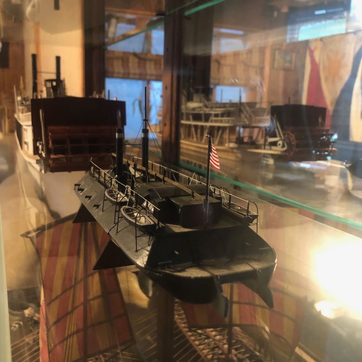
Thanks, Mark. It's definitely easy for kit flaws to undermine a build. I'm just too bloody stubborn to give up! Plus I'm enough of an environmentalist to have a really strong aversion to trashing something. I should clarify, for those who aren't necessarily familiar with my past projects, the two other steamboats are scratchbuilt and the Viking longship is a heavily modified Dusek kit (see links in my signature).
- 113 replies
-
- 7
-
-
- Cairo
- BlueJacket Shipcrafters
- (and 1 more)
-
OK, with night falling, here are a couple more photos of the finished model in the display cabinet, with fewer reflections. I also want to correct an omission in the earlier posts and say Thank You so much for those who stuck with this build log. It can't have been the most fun, with me complaining a lot and the result being not that great. But having community support makes such a difference, it adds so much to the model-building experience. Hopefully the next project will be more fun for everyone!


- 113 replies
-
- 12
-

-
-
- Cairo
- BlueJacket Shipcrafters
- (and 1 more)
-
Dust masks and respirators.
Cathead replied to Bill Hudson's topic in Modeling tools and Workshop Equipment
I hate wearing masks (yes, pre-covid) because they quickly give me headaches. Something about the air restriction (and if they're not restricting your air, you're not wearing them right). They're a miserable experience for me after about 10 minutes. But I still use them for anything over light hand-sanding. Sawdust just isn't good for the lungs and it's not worth the complications. I also try to do heavier sanding outdoors whenever possible. Also, as noted above, some woods are more hazardous than others.