Cathead
-
Posts
3,522 -
Joined
-
Last visited
Content Type
Profiles
Forums
Gallery
Events
Everything posted by Cathead
-
 Thanks for starting this! You've shot ahead of me as I've been out of town most of the week, so now I can use you as a trailblazer. Looks like you got the right-shaped hull and casement pieces, unlike the oddball pieces that showed up in my kit (and that BlueJacket quickly replaced). Keep up the good work.
 -
Lovely! A pride-worthy endeavour. I hope you enjoy viewing it for many years to come, and thanks for sharing your work with us.
- 104 replies
-
- 1
-

-
- Bluejacket Shipcrafters
- smuggler
- (and 1 more)
-
Timber-framed outdoor kitchen - Cathead - 1:1 scale
Cathead replied to Cathead's topic in Non-ship/categorised builds
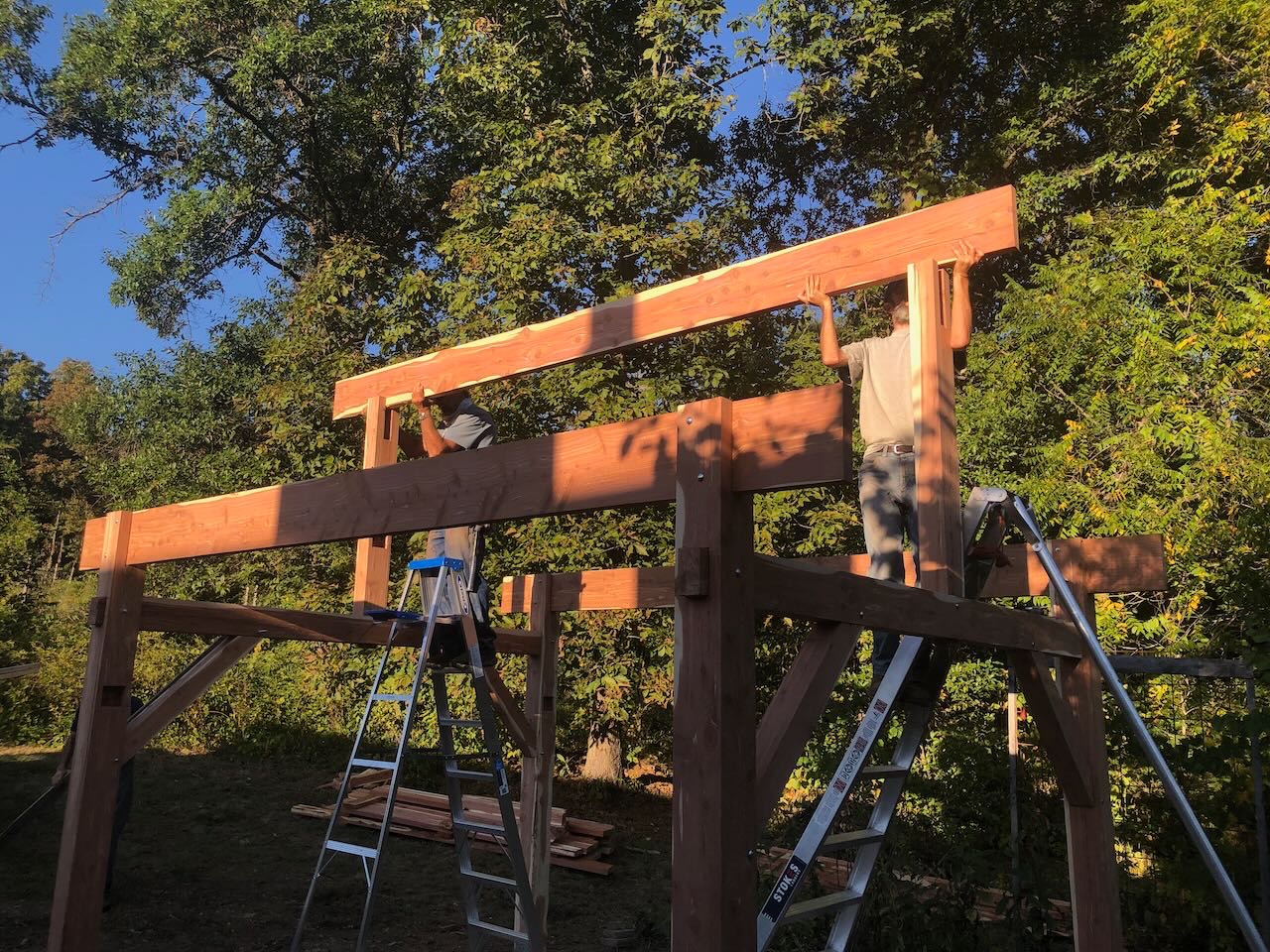
Another productive day, but only one image. After assembling most of what we'd pre-prepared, it was back to manufacturing. My stepfather spent much of the day carefully setting up a jig to precision-cut all the rafters so they'll drop nicely onto the beams, and finished cutting them as the day ended. I got all the longitudinal angle braces finished and installed; these definitely had some quirks and took some adjustments to fit right. It doesn't look all that different overall, but it's another day closer to completion. We had various other friends and neighbors stop by to help out and socialize; all weekend has been like a grand old neighborhood barn-raising with a nice community of people. Work will stop now for a week, as the reward for a week of hard work is a week of hiking/floating/sightseeing in the Missouri Ozarks and a quick trip to Kansas City. So I won't be getting back to this until early October. But the building is now nice and strong and can wait quietly for me to return. Thanks for reading, take care, looking forward to being able to update again in a week or so.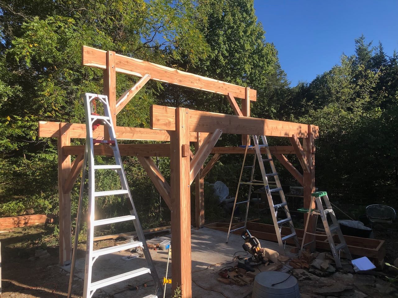
- 131 replies
-
- 13
-
-
@rcmdrvr Welcome! I find build logs to be a really useful resource, both for advice and help, but also for motivation. Knowing others are paying attention to, and care about, my work, helps keep me going and helps discourage sloppiness.
- 113 replies
-
- 4
-
-
- Cairo
- BlueJacket Shipcrafters
- (and 1 more)
-
Got them, wonderful resource, thank you! May not get back to this project right away as (a) still very involved in kitchen-building and (b) will be taking my stepfather on a hiking/floating trip in the Ozarks next week as a thank-you reward for all the hard work this week. Plus I want to wait for the new hull from BlueJacket.
- 113 replies
-
- 4
-
-
- Cairo
- BlueJacket Shipcrafters
- (and 1 more)
-
Timber-framed outdoor kitchen - Cathead - 1:1 scale
Cathead replied to Cathead's topic in Non-ship/categorised builds
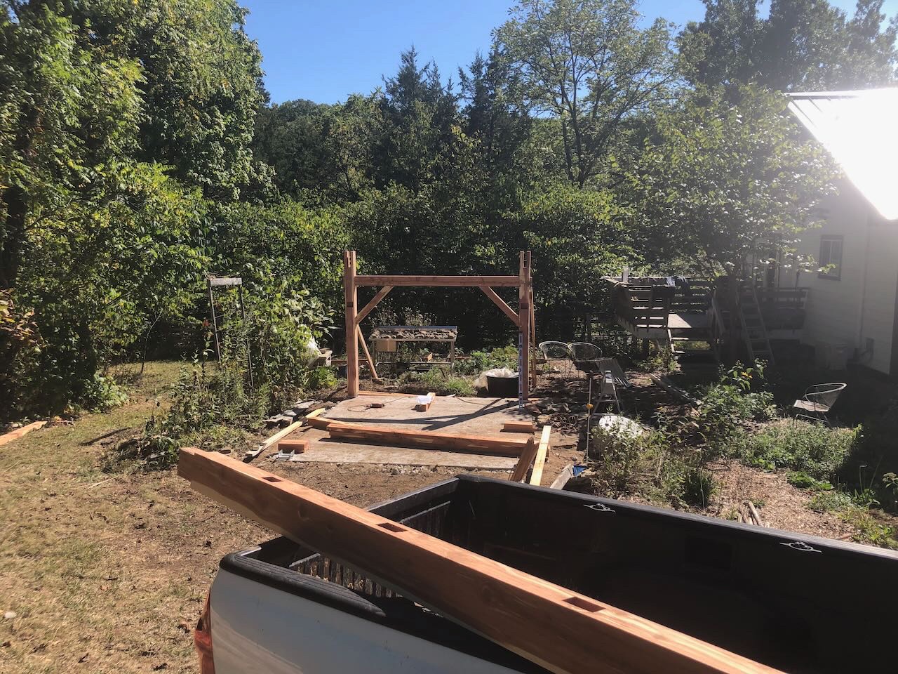
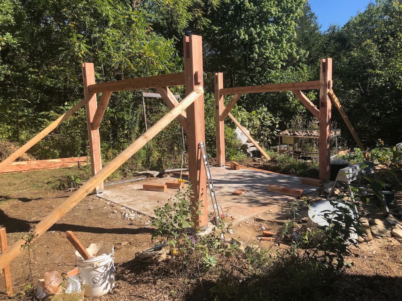
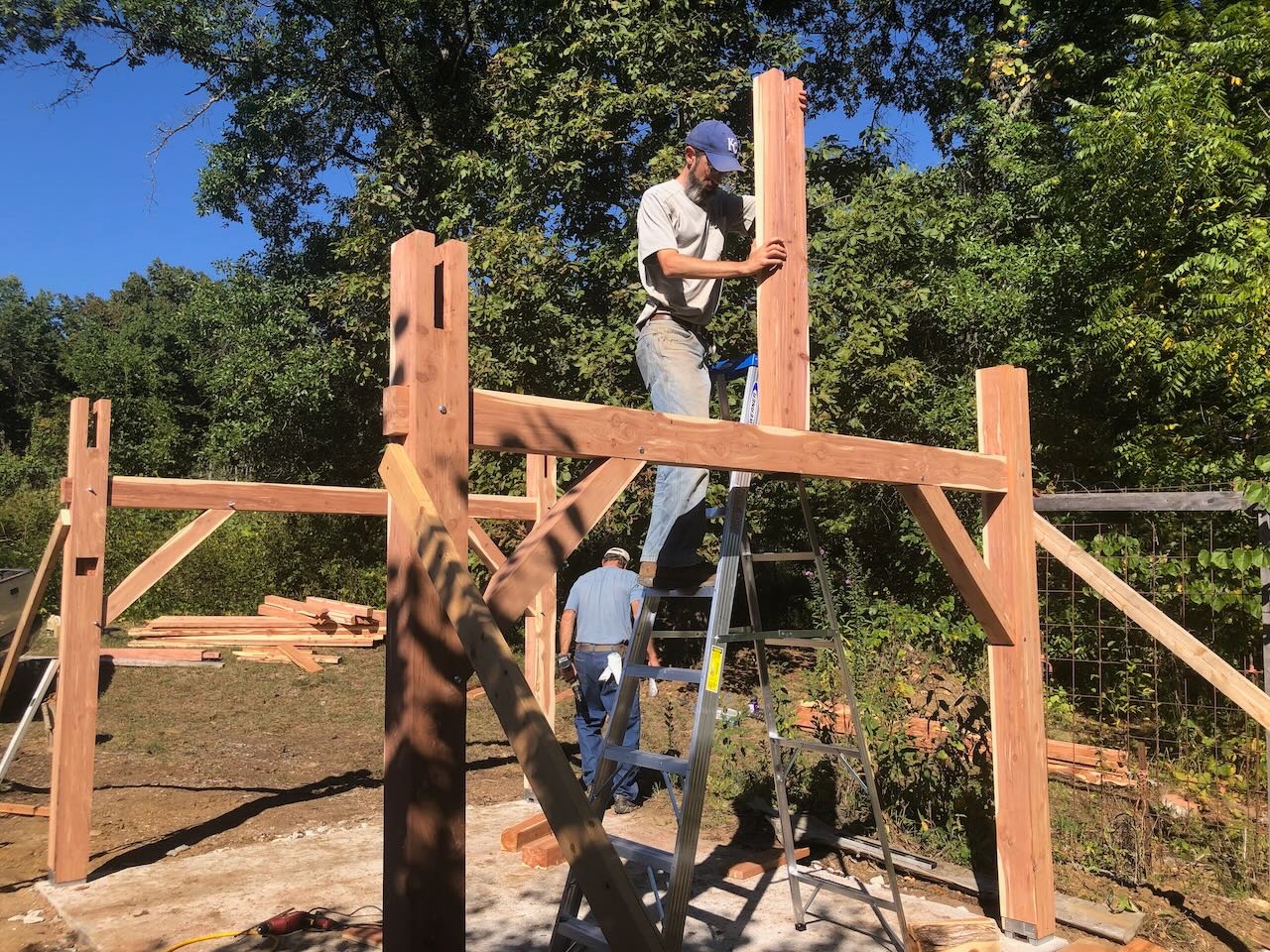
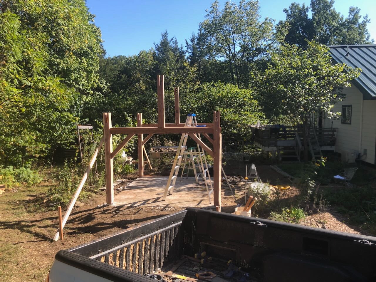
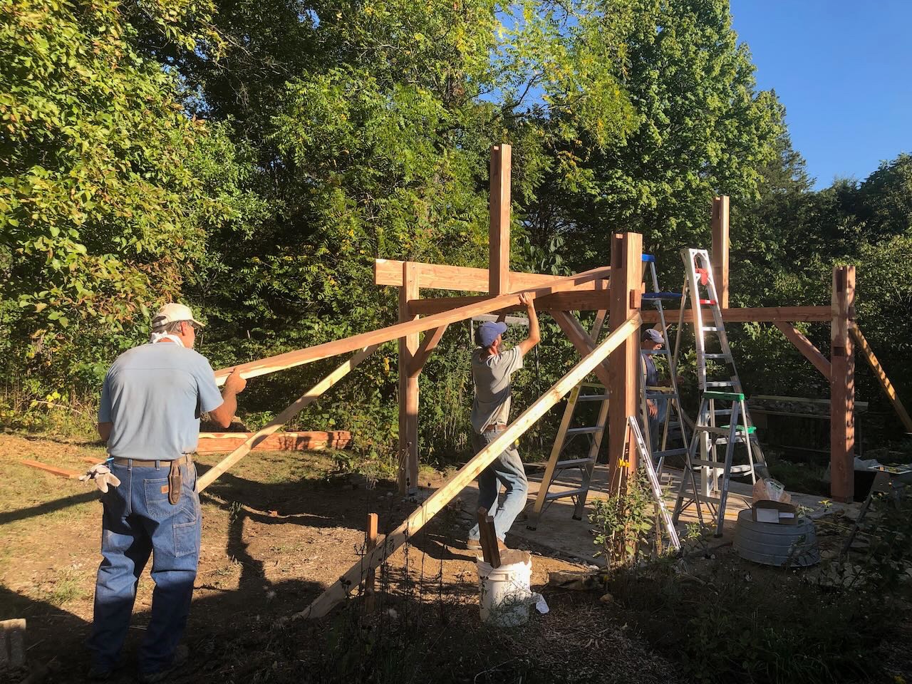
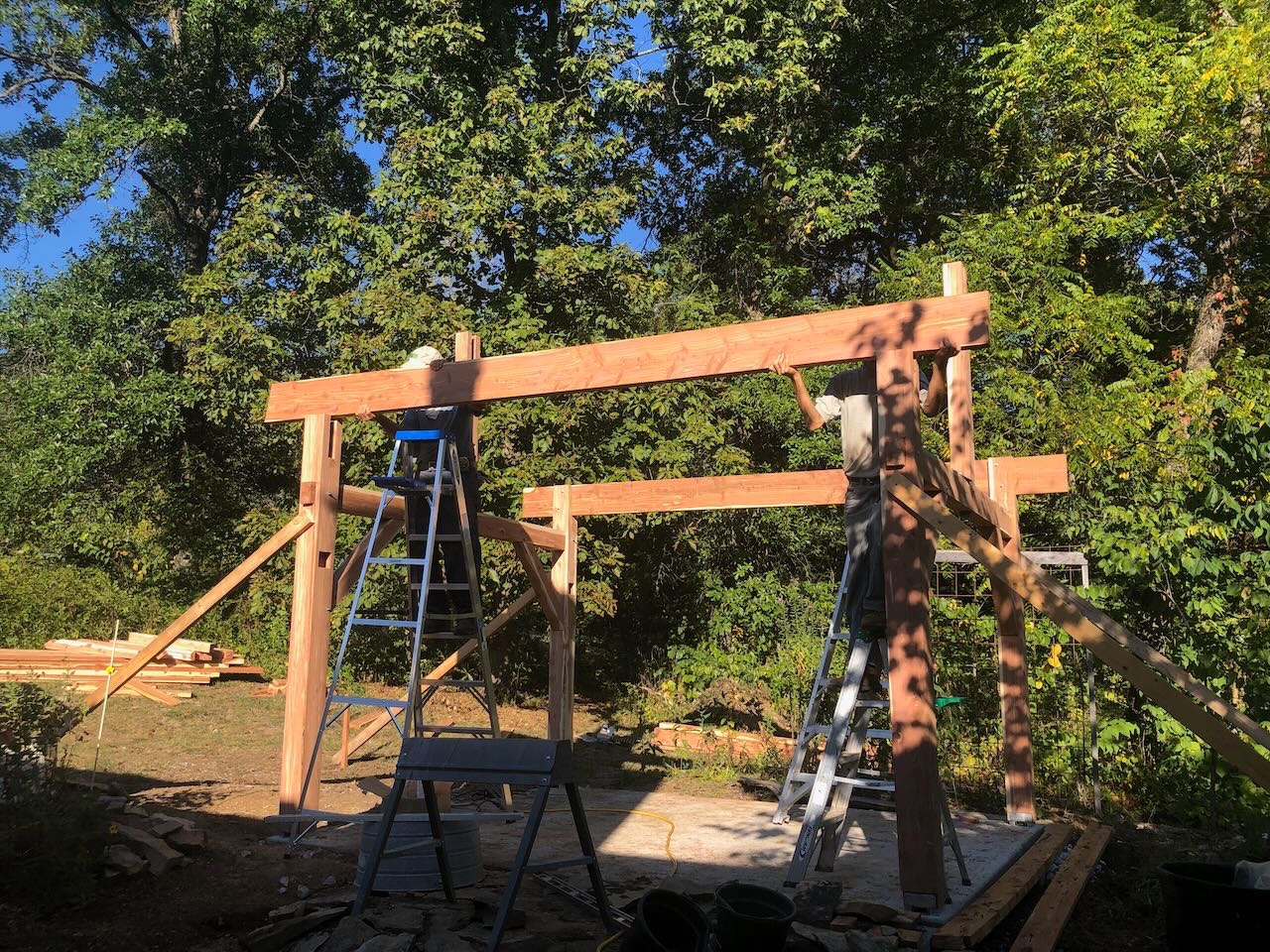
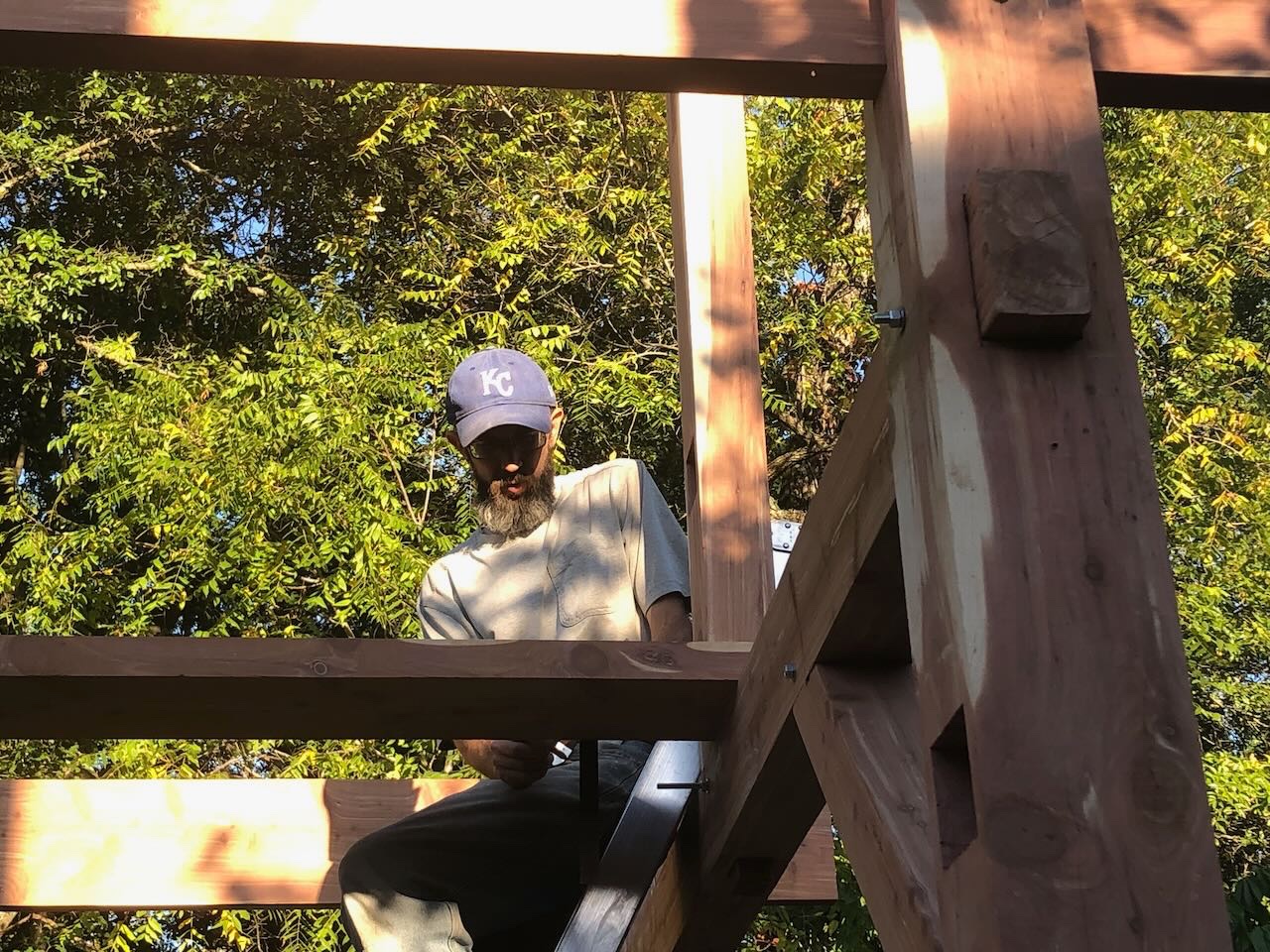
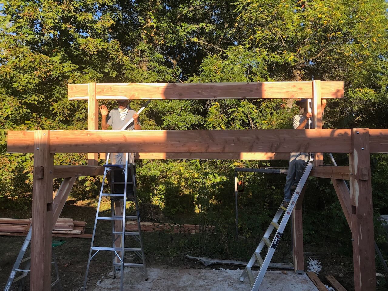
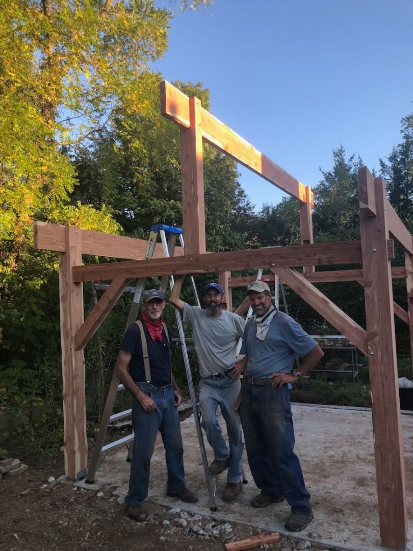
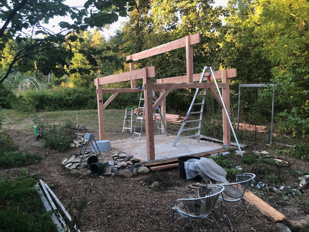
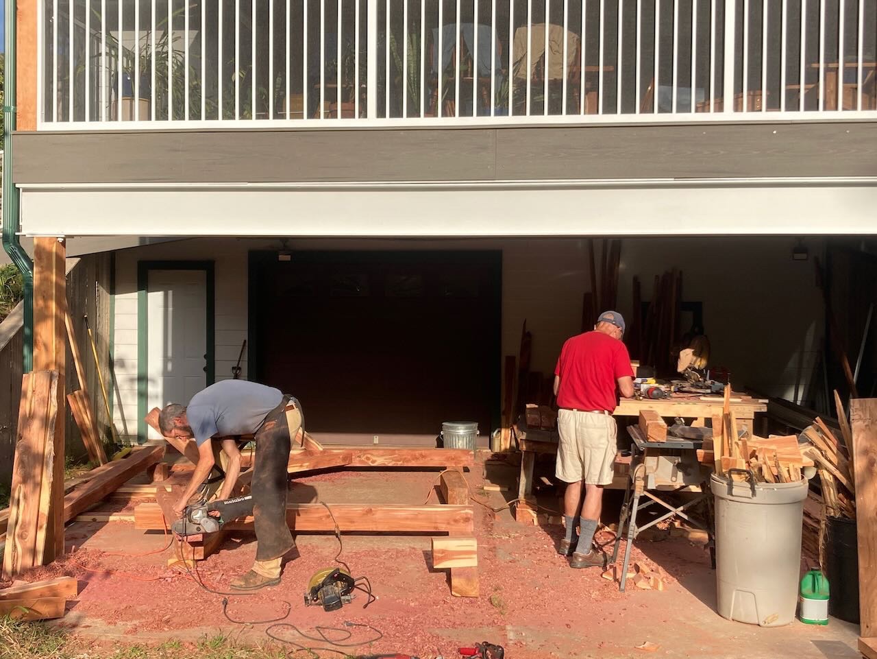
Today we started assembling and raising the structure. We essentially declared an open house at the farm over the weekend, with various friends and neighbors invited to stop by and help as desired, which they did. One fellow showed up in the morning and stayed through evening, he was having such a good time. We'd made a bunch of food and had a nice spread available for snacking (sourdough bread, homemade hummus, grain salad with garden veggies, homemade sumac wine, orchard persimmons and pears, etc.). I'm too tired to go into serious detail, but here's a photo essay of the day's progress. Hauling the "kit" up around behind the house: First frame assembled, bolted together, and raised: Second frame assembled, bolted, and raised. Both frames braced temporarily: Setting a king post: Both kingposts installed: Getting the large longitudinal beams up onto the structure: Setting a beam in place (I designed the structure so these heavy pieces would just drop into their slots, with minimal fussing): Marking the external overhang on a beam before raising it into its slot: Raising the center beam onto the king posts: Checking for plum and making final adjustments: A dusty, tired, happy work crew (stepfather on left, me at center, super-helpful friend at right): Status at end of day. You can also see more of Mrs. Cathead's work on the creekstone walkway left of the structure: We took some really cool time lapses of the construction process, which at some point I'll edit into something I can share. But not right now, I'm whipped. Tomorrow is more of the same. A variety of friends and neighbors stopping by throughout the day, lots of good on-farm food on hand, glorious weather (sunny and temperate both days). Tomorrow we'll cut and install the six angled braces that help support the longitudinal beams, then move on to shaping rafters. Like many models, this looks great from afar, but has some flaws when you look closely. Some of the joinery doesn't match as well as it seemed to when we tested it in the workshop, but it all holds together nicely in the end. Bolts cover many sins. You'll notice I stuck to faraway shots! Overall I'm pretty thrilled with how this came together, my schedule for the week has played out the way I hoped and this was what I hoped to achieve by the end of today. Thanks for reading, hope you enjoy the photos. We'll see what tomorrow brings.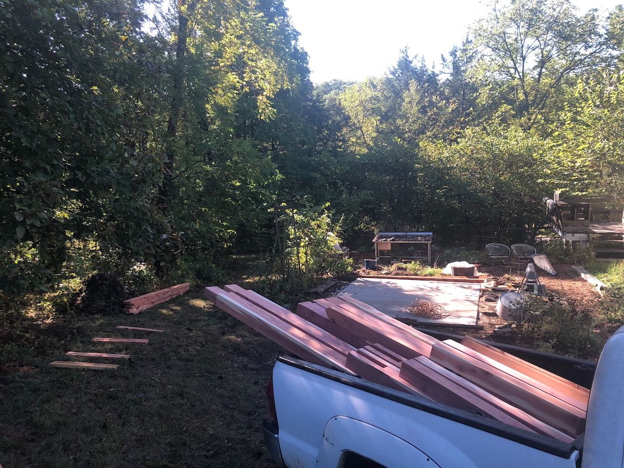
- 131 replies
-
- 14
-
-

-
Thanks, Nic, that's a relief! Will look forward to the new piece. I'll send you a PM with the order number to ensure you know where to send it. Brian, it would certainly be interesting to see your plans if it's not too much trouble. Did you mean digital or mail?
- 113 replies
-
- 3
-
-
- Cairo
- BlueJacket Shipcrafters
- (and 1 more)
-
Mark, I should have clarified that the instructions do provide a clear photo of how to round the stern sections, but not for any other part.
- 113 replies
-
- 3
-
-
- Cairo
- BlueJacket Shipcrafters
- (and 1 more)
-
It's amazing how well a rough hull transforms into something lovely with sanding.
-
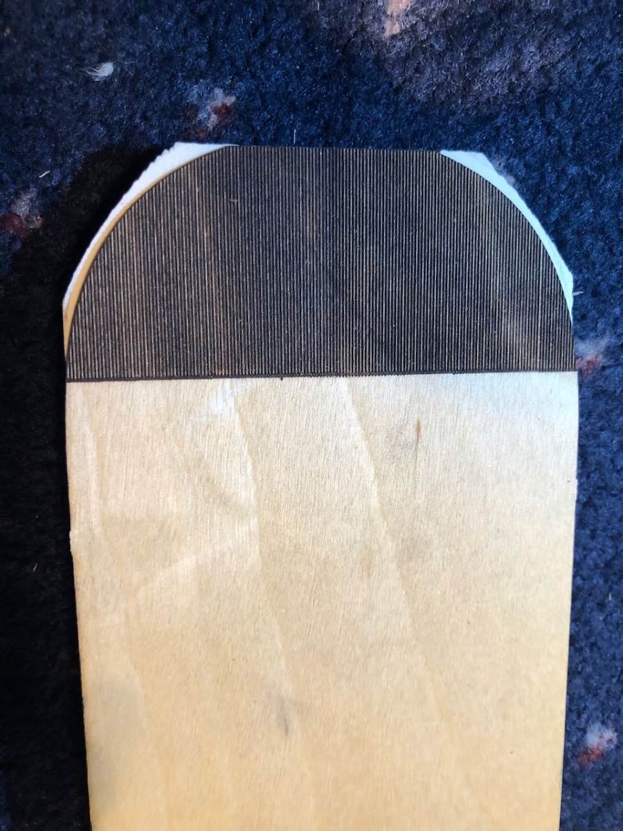
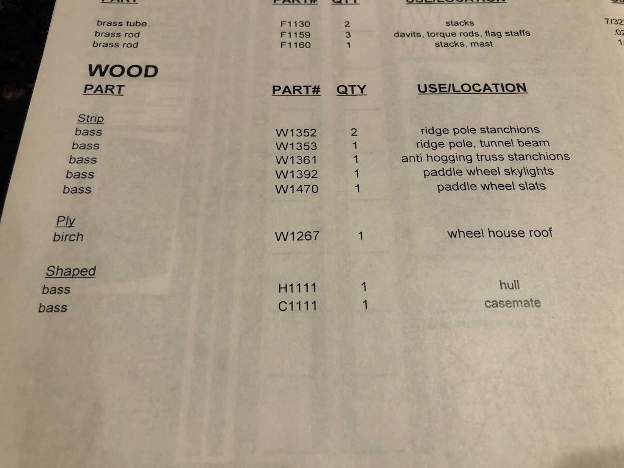
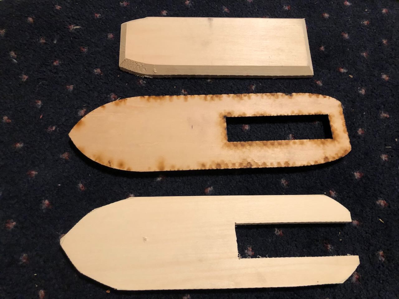
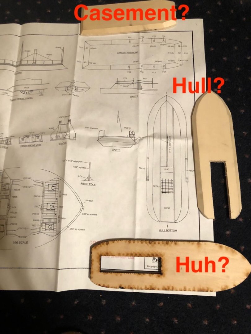
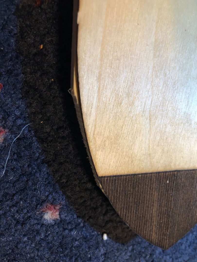
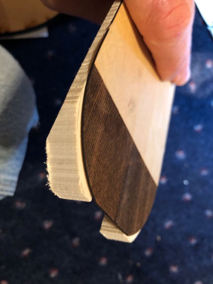
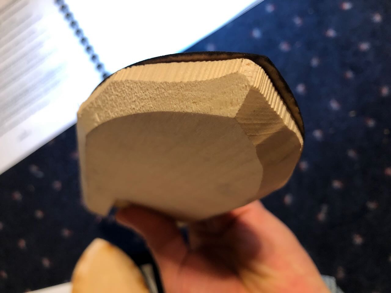
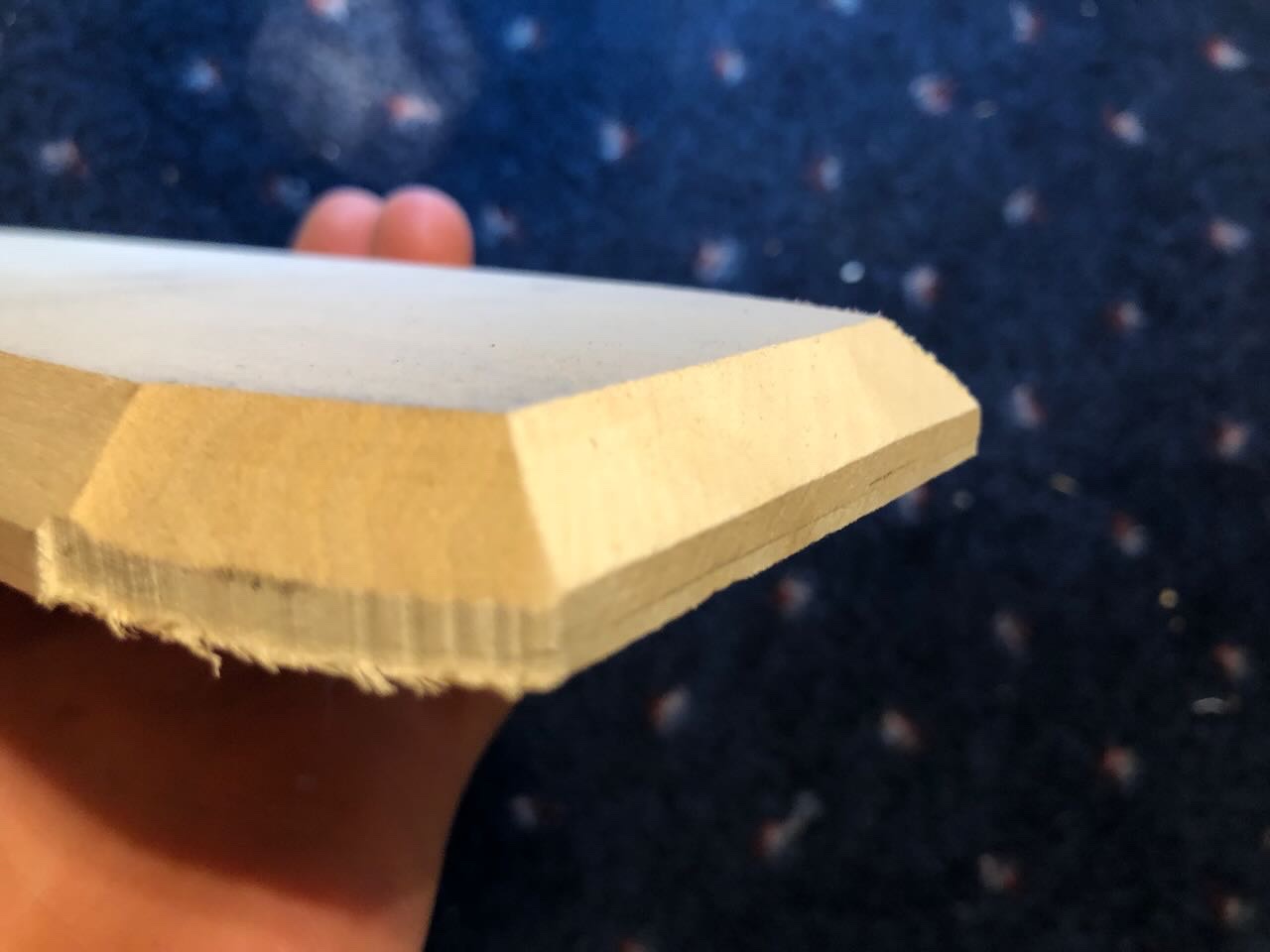
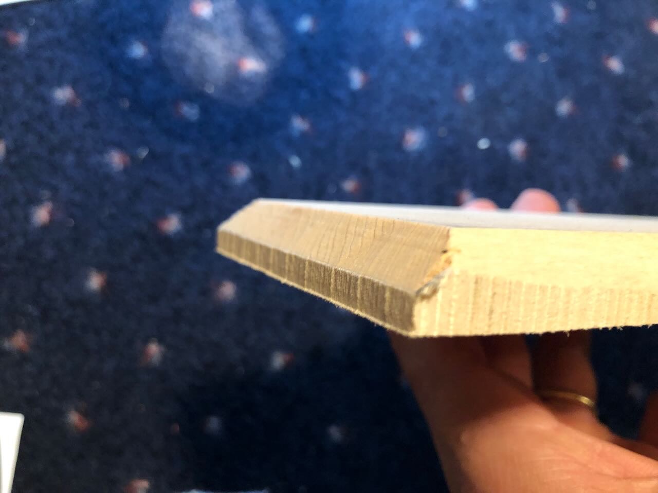
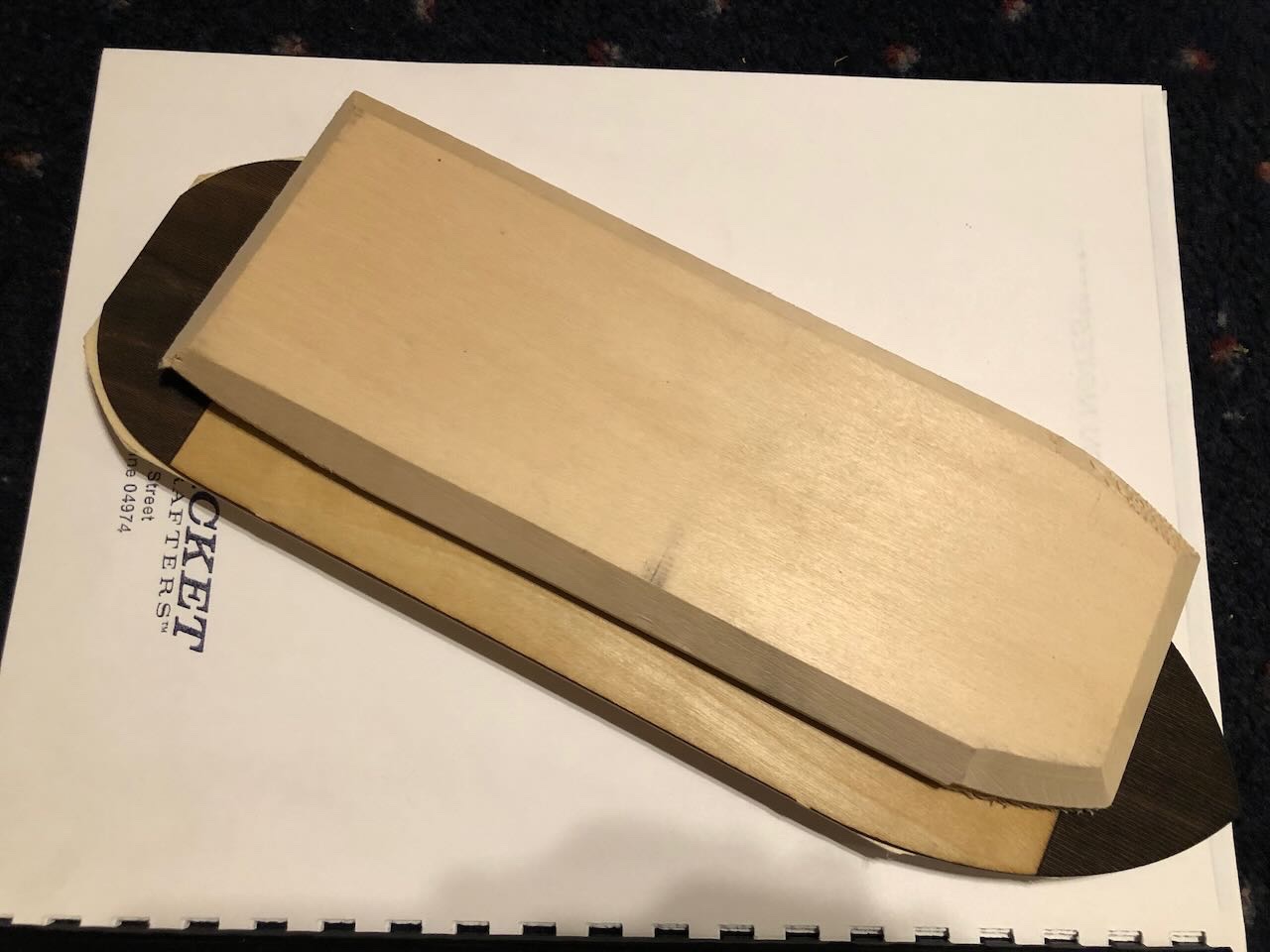
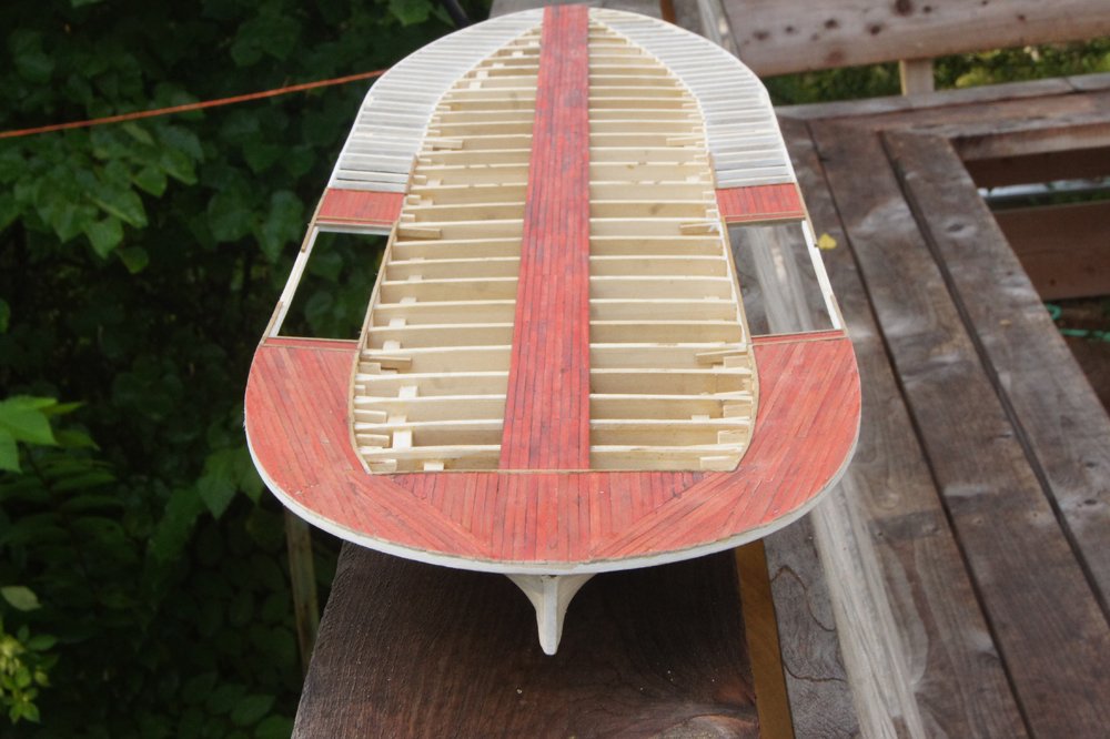
So after an intense week cutting and shaping all the parts for the outdoor kitchen (essentially making the "kit" we'll start assembling this weekend), I decided to take Friday evening to relax and fiddle with my other kit. By the way, if you want to follow the kitchen project, I yielded to peer pressure and started a Shore Leave build log. I started reading through the instructions and comparing them to the kit contents and, unfortunately, halfway through the first page I'm already pretty confused. The instructions are pretty minimalist with almost no useful graphics or drawings. Let's work through my confusion step by step. LATER EDIT: Most of the confusion related below turns out to have been caused by faulty hull and casement pieces in the kit I was sent. After I sent a message to BlueJacket asking about this, they promptly sent out new parts which are much cleaner and clear up most of the confusion. See later posts in this thread. Just noting it here so prospective builders aren't scared off; you shouldn't expect to see the parts below in your kit! Although the instructions remain a bit vague, proper kit parts make it much easier to work out what to do. Question 1: What is this piece? There are three big pieces of hull-shaped wood in my box. Unfortunately, only two seem to exist in the instructions: casement and hull: And the plans pretty clearly show a two-part hull; I'm pretty convinced I've identified the listed casement and hull. The mystery/extra piece seems to be the extra-charred piece in the middle of the first photo, as it doesn't correspond to anything on the plans: So what is this? A packing mistake? Question 2: Is gluing the laser-cut deck on before sanding the hull really a good idea? The hull/casement pieces are VERY rough and will need extensive smoothing and reshaping. The very first step in the entire project is to glue the thin laser-cut main deck sheet onto the solid hull, before doing any shaping. This order makes me very nervous. First, it'd be really easy to take off too much of the deck while sanding the much thicker hull. Why not do rough shaping BEFORE gluing on the thin deck? Here are four photos showing how the deck looks when held onto the hull. The instructions blandly say "align it [the deck] with the hull and glue it in place" but it doesn't feel that simple. Notice in the photos below that the deck both overlaps and underlaps the hull in places, so how to achieve a smooth line along the entire thing? They also say that the deck should be slightly wider than the hull, but mine seems to fit with no overhang. Question 3: Is gluing the casement onto the deck before sanding really a good idea? Similar to Question 2, the instructions next tell you to glue the casement to the top of the main deck before doing most shaping (they do tell you to sand the fore/aft parts, presumably because these cut across the deck surface). But as with the hull, there's a LOT of shaping to be done, and it makes me nervous to do this with the thin deck already glued on. Here's the very rough casement piece: Basically, you're supposed to make a hull-deck-casement sandwich before doing any shaping around the perimeter, and that just makes me really nervous. Question 4: What's the intended shape of the hull/casement when sanded? Guidance for shaping the hull/casement is also very limited. The instructions just say "sand the hull and casement sides smooth". OK...does that mean convert the two angles present to one single surface? Or sand both surfaces smooth, preserving the original angles? If they're supposed to be one surface, why not just cut the piece that way in the first place? Same question for the hull, which is also a rough two-angle surface over much of the piece (see earlier photos). The plans imply that all of these pieces should be single surfaces from top to bottom, but it's not made clear and is really making me hesitate. The curve of the bow is also pretty inconsistent on the port and starboard side, which will make shaping extra-fun. Question 5: How to align the casement on the hull? When it's time to glue the casement on, the instructions just say "mark the location of the casement on the main deck and glue it in place". OK...based on what? I guess measurements from the plans? This is confusing because the scribing on the deck extends well underneath what the casement would cover, so it's initially unclear whether we're supposed to be lining up one of the casement ends with where the scribing stops: As far as I can tell, and based on the plans, you just have to overlap the deck scribing at both ends, but this seems unnecessarily confusing to me. So far, not that impressed. I'm a few paragraphs in, already I have five questions that are confusing me, I just spent a bunch of time photographing and writing up these questions, and I'm definitely not relaxed. I'd be very grateful if @MrBlueJacket is around and could clarify these for me. I think I understand how things are meant to align (based on the plans and writing up these questions), but it took a while to figure out from the vague instructions. I'm a reasonably experienced modeler and wasn't expecting to be this stumped this quickly. BlueJacket sells a separate CD of build images that would probably be really helpful in figuring out stuff like this, but I didn't buy it. Felt kind of like a luggage charge, and I thought it was reasonable to think the original instructions and plans would be sufficient. Maybe I'm just thinking slowly after a long week of 1:1 scale woodworking, but these seem like questions that could confuse other builders, especially new ones. Probably won't get back to this for a few days, so letting these ideas simmer will probably help me sort them out, along with any suggestions/interpretations from commenters. Thanks for reading, hopefully I can show some actual progress soon!

- 113 replies
-
- 6
-

-
-
- Cairo
- BlueJacket Shipcrafters
- (and 1 more)
-
A hint for future builds, you can see some places in the planking where there are pretty clear knuckles, which tells you that the underlying frame could have used more fairing. All the planking should be perfectly smooth, ideally you shouldn't be able to tell where the frames are. But as said before, some nice filling and sanding will work wonders, as will paint. And you've kept the planking runs straight, avoiding the dreaded upward-sweeping bow curve that happens when people don't pay attention to how hull planking works. I forget, is this a double-planked hull or is that the outer layer?
-
Sorry I didn't catch up on this until now. I've never done a double-planked hull but I think I've seen advice elsewhere to primarily wood glue but use small spots of quick-curing CA to hold the planks down while the wood glue dries (which still doesn't take long when you use a thin layer). But make sure you use a thin layer of glue, overdoing it will warp planks and make a mess. Stern repair looks nice.
-
Polaris by JDillon - OcCre
Cathead replied to JDillon's topic in - Kit build logs for subjects built from 1801 - 1850
Have you considered making some simple drawings, using colored pencils to sketch out different color schemes? If you have digital skills you could take a photo of the hull and use a simple art program to lay different colors over that. Having a set of comparable images/drawings in different color patterns may help you (and anyone you want to run it by) make a decision. -
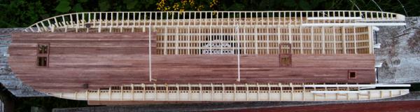
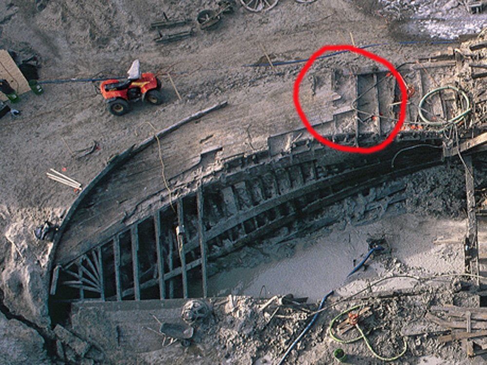
@juhu, that image is from my scratchbuild of Arabia, an 1856 sidewheeler, so isn't directly relevant to Chaperon, an 1884 sternwheeler. In that case, the planking layout was based on photos of the wreck as it was excavated. The remaining planking was incomplete but clearly showed a set of angles converging toward the stern, following the boundary between guards and hull, with a straight run of planking only being found within the hull: For visual comparison, here's the photo you referred to, which was my interpretation of the evidence available: There was a discussion of this planking in the log, starting with this post, if you want to read more. Only a tiny fraction of riverboats built were ever photographed, and especially not from angles that clearly showed the layout of their deck planking, so we can only draw so many broad conclusions. Even fewer have been found and excavated. Also note that the planking pattern you're asking about is at the stern, not the stem. Arabia was a sidewheeler, while Chaperon was a sternwheeler, so the deck and hull layouts were quite different. Sternwheelers had a much squarer end, more like a barge, to support the sternwheel, while sidewheelers had a rounded stern more like a normal ship because the wheels were along the sides. For example, Bertrand, an 1865 sternwheeler, had a straight run of planking all the way along, like the kit depicts for Chaperon. We know this from the archeological drawings from her excavation; here's a photo of her planking underway on my model (based on those drawings), where you can see that the layout is pretty similar to Chaperon. I'd say the Chaperon kit has it right, between the fact that it's a more recent and well-documented prototype, as well as being a sternwheeler whose hull shape lends itself to straight planking.
- 158 replies
-
- 3
-
-

-
- chaperon
- Model Shipways
- (and 1 more)
-
Timber-framed outdoor kitchen - Cathead - 1:1 scale
Cathead replied to Cathead's topic in Non-ship/categorised builds
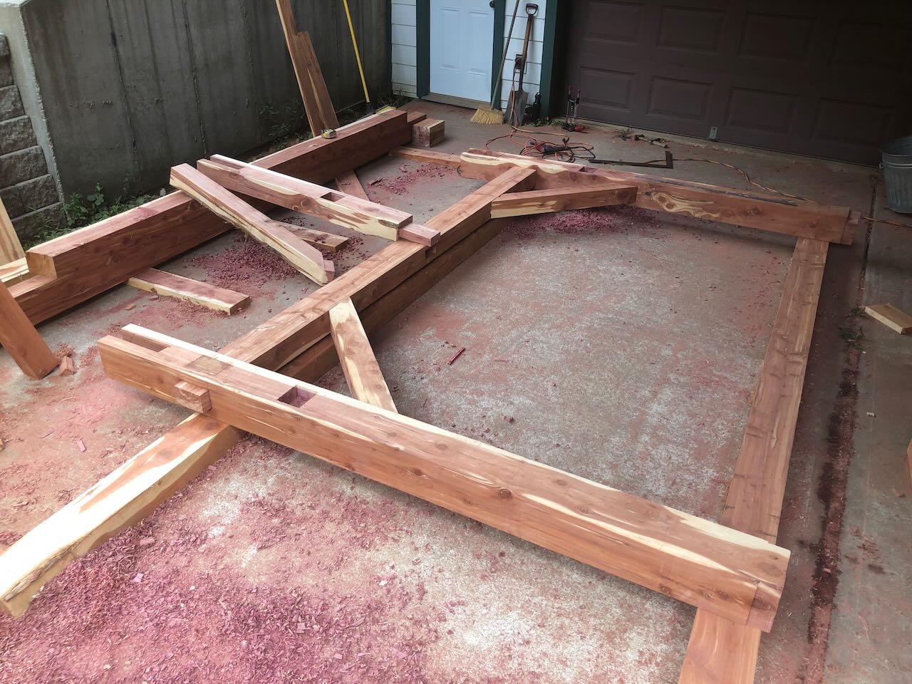
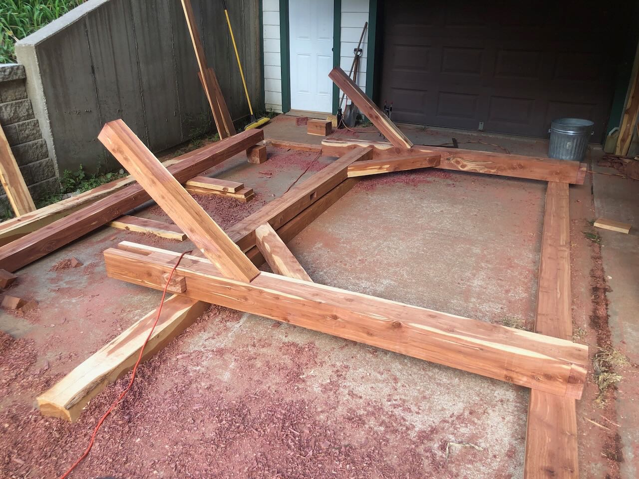
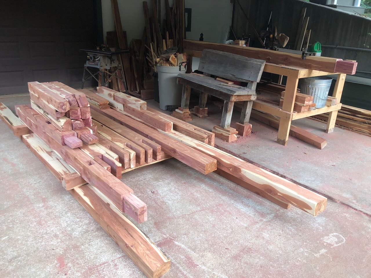
Those were all closeups, so let's take a broader view of today's work. First, here's the glorious bank of clouds sweeping in with the cold front. Quite a change from the blazing clear sky: Here are a couple shots Mrs. Cathead took of us working in some nice afternoon light; by this point the temperature had dropped so far that the sun felt good rather than brutal: Here are two shots of a completed frame being test fit: Using the diagonal method to check square, this came out to < 1/2" off-square for an 8'x10' frame. Seems acceptable for hill country carpentry. We got a good start on the second frame before dinner time. With a chance of rain overnight as this cold front passes, we cleaned up the workspace and stacked all the pieces well off the ground and under cover. Seems so small like this: Tomorrow I hope we can finish the other frame, putting us on track for erecting the structure this weekend, as Friday will be somewhat busy with other commitments. Not sure that really does the last few days justice, but maybe you get the idea. Will be really fun when I can show photos of this all coming together in 3D. Thanks for following along! EDIT: Meant to add that, at dinner, we rewarded ourselves with 100% on-farm tacos (home-grown and -processed corn tortillas, stuffed with garden beans, peppers, onions, and tomatoes, along with log-grown shiitake mushrooms). OK, I lied, we added grated cheese from a good friend's nearby goat dairy. Also a big pile of fresh sweet corn picked 10 minutes before dinner. Fresh pears and persimmons from our orchard are also abundant right now.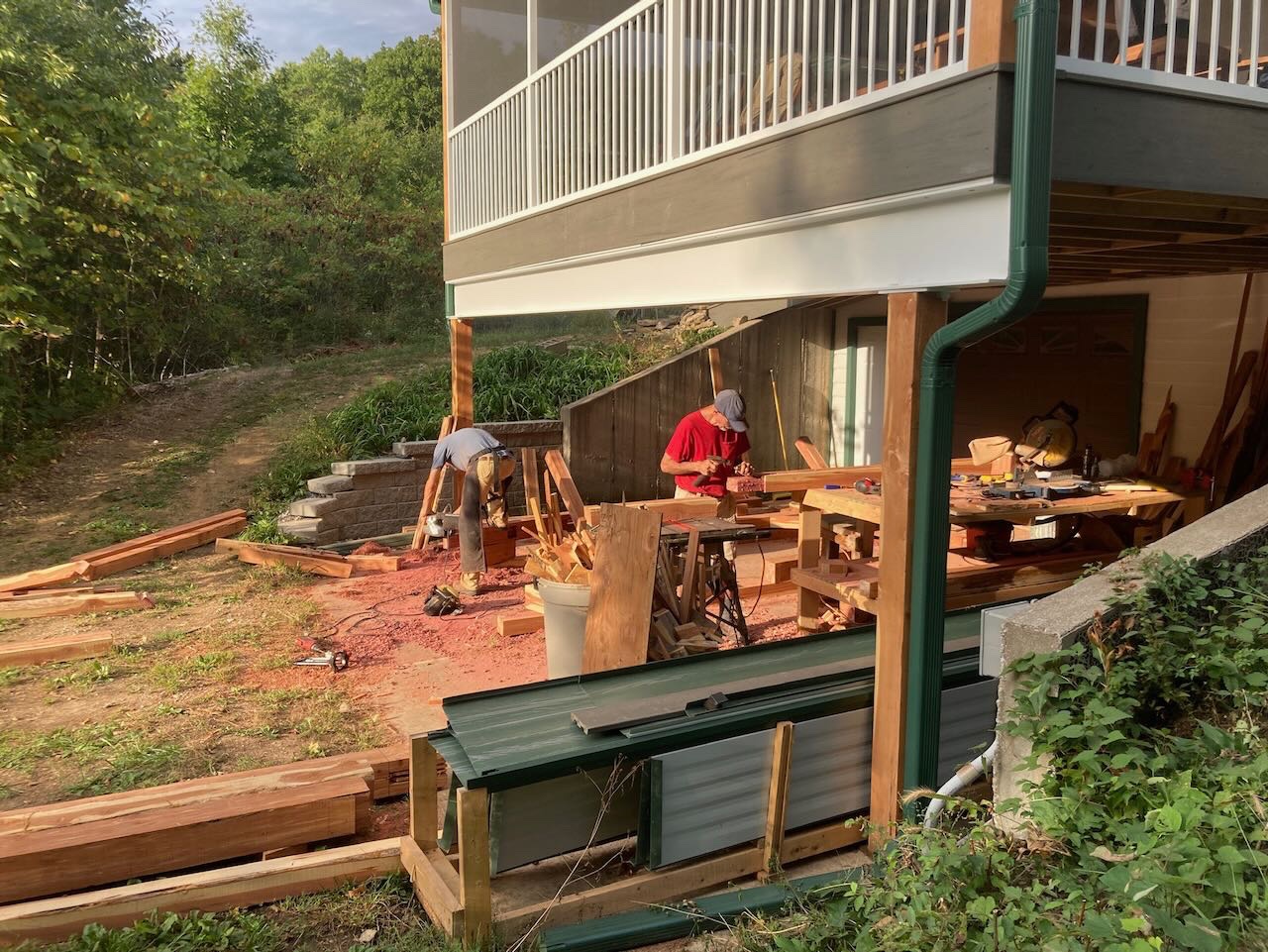

- 131 replies
-
- 10
-
-
-
Timber-framed outdoor kitchen - Cathead - 1:1 scale
Cathead replied to Cathead's topic in Non-ship/categorised builds
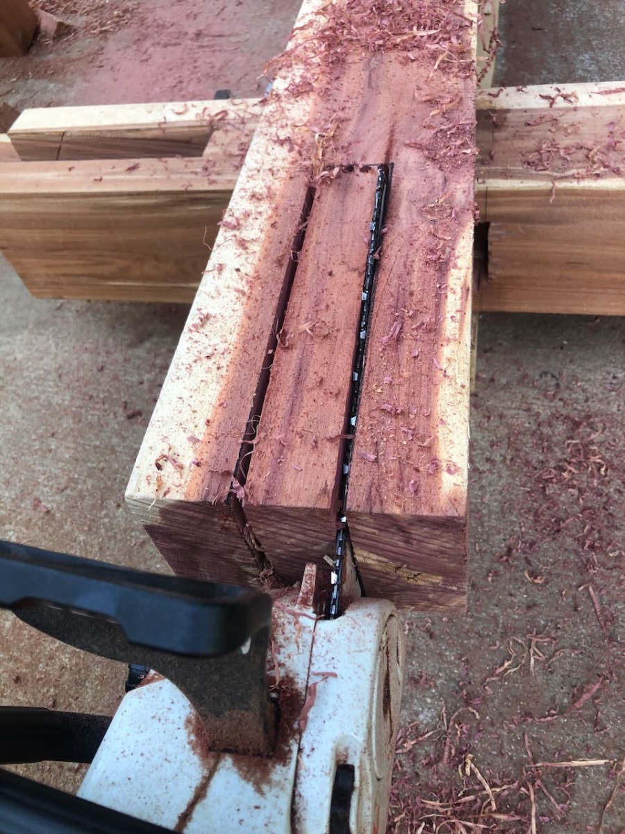
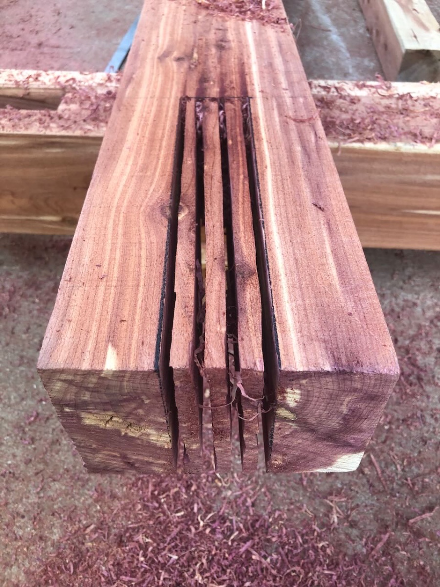
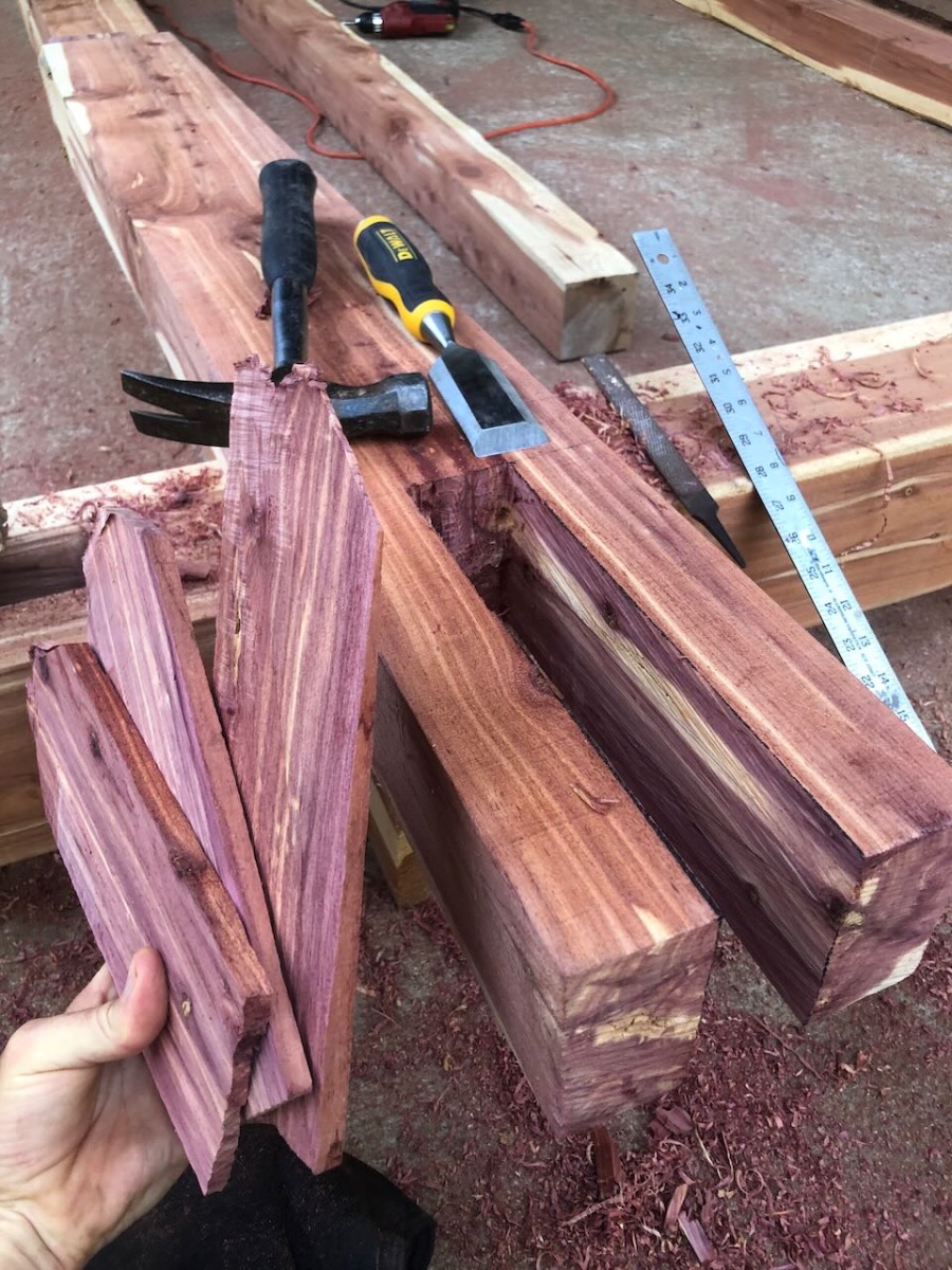
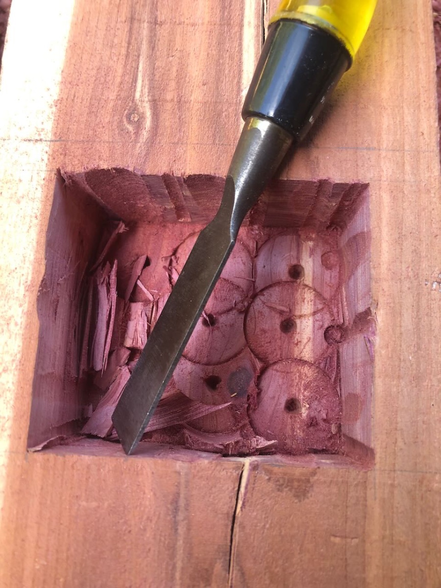
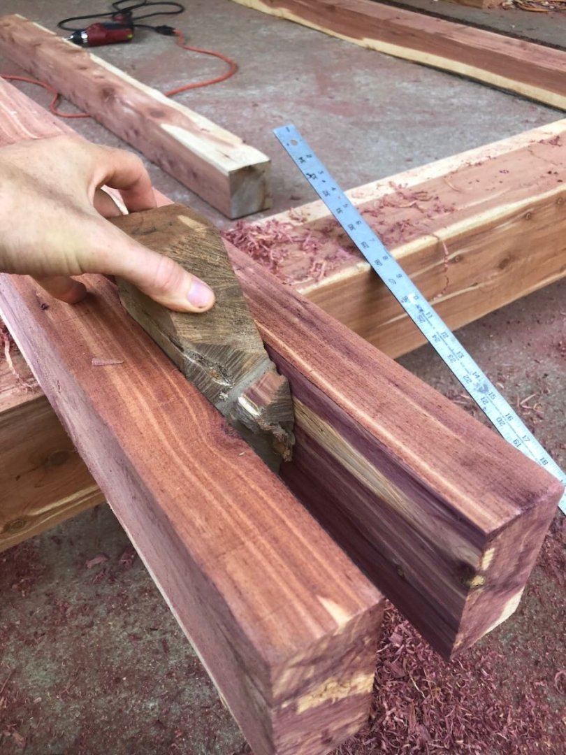
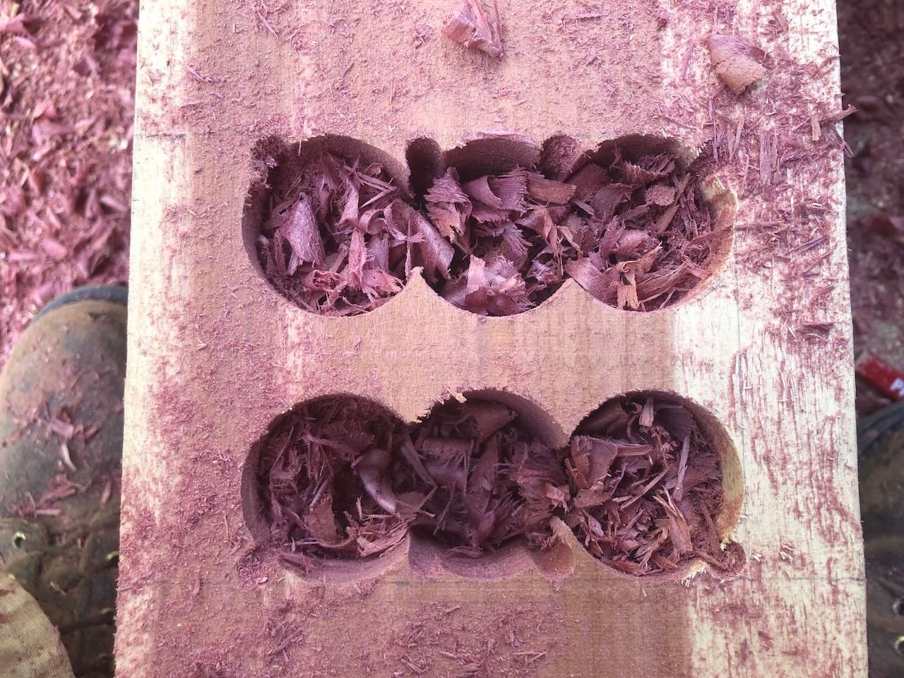
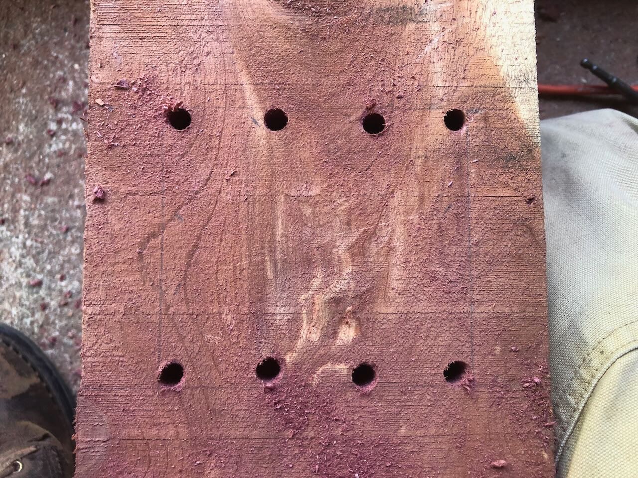
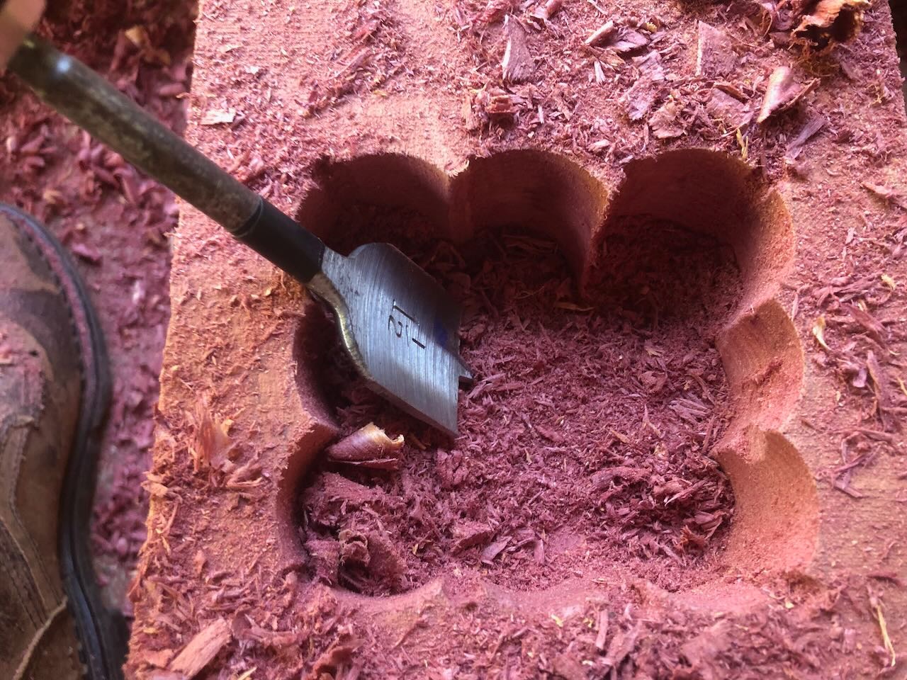
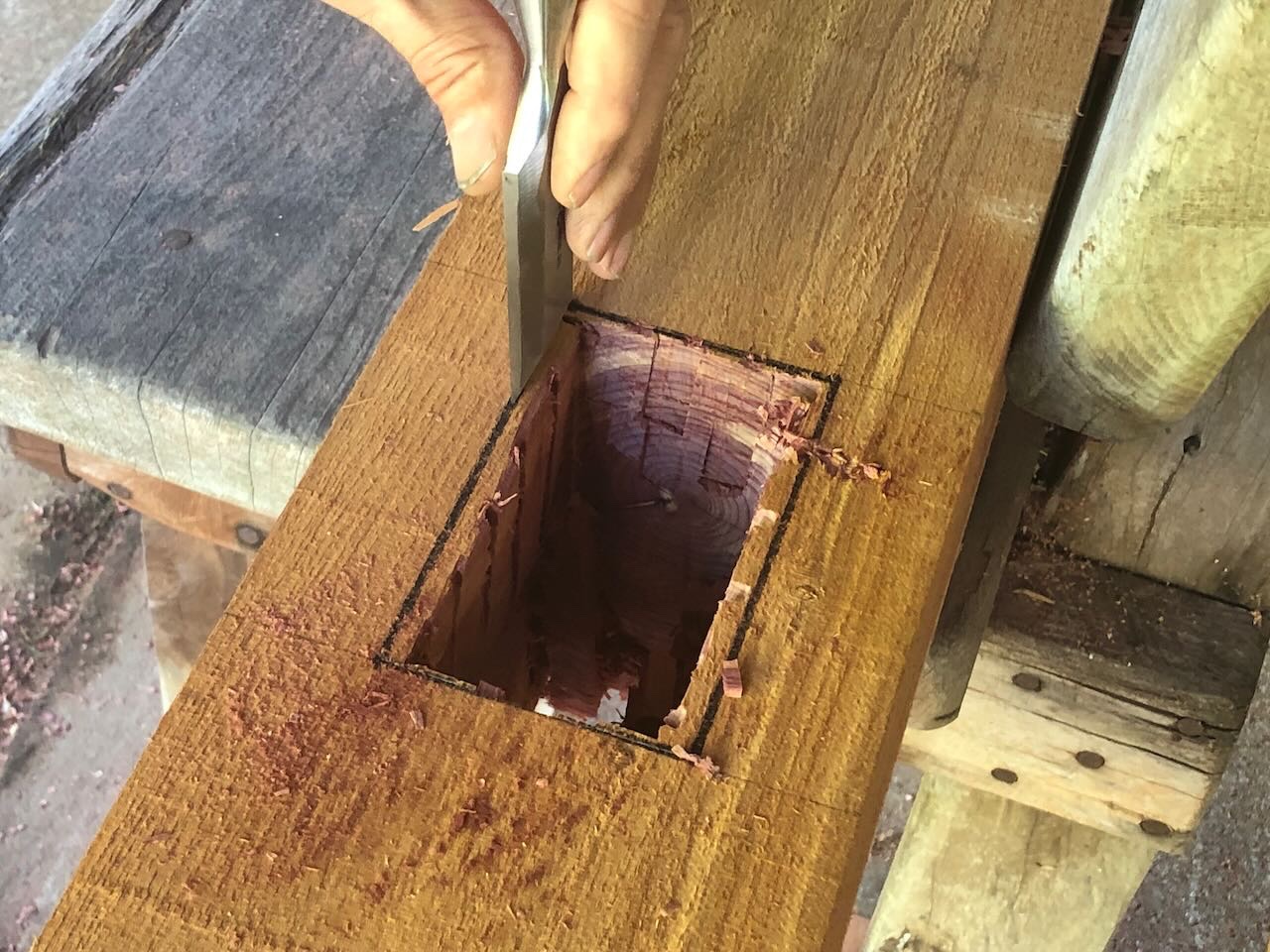
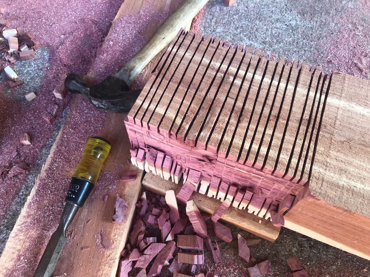
It's actually been a very dry heat, more like North Texas or New Mexico. We've been in moderate to strong drought most of the summer, and this late fall heat especially has been desiccating. A minor blessing, since I'd much rather work in dry heat than Missouri's normal swamp-like humidity. On to the project update! It started out brutally hot again, racing up above 90º by noon, but then the cold front arrived. Clouds built in, cooler winds started to blow, and the afternoon was quite lovely. We're forecast for a high of 68º by Thursday and 62º on Friday. We got a lot done and I'm feeling pretty good about the timeline. Here's a sequence showing how I cut the long, thin mortises at the top of the posts, which will hold the 2x10 main beams. After measuring out the slot, I drilled out the ends to make chiseling easier, then cut the outer edges freehand with a chainsaw: I then cut a few inner slots with the chainsaw to ease material removal: I then used a chisel to empty the slot and clean up the interior: And finally tested the fit with a scrap piece of 2x10: Elsewhere, we cut a lot of mortises and tenons for all the different angled supports. Here's my usual way of doing that. After measuring the mortise, I used a small drill to mark the corners and edges: I then used a 1-1/2" spade bit to ream out most of the area. I used a drilling jig with a stopper to get the depth roughly right. Notice how I used the small drill bit to pre-open the areas the spade bit wouldn't reach: I then used a chisel to clean up the edges and interior: Cutting the tenons was pretty straightforward and I only took one photo. I just marked out the area, use a circular saw set to the right depth to cut a bunch of slots, then cleaned them out with a chisel. Here's what it looked like partway through one: With that I hit the system's photo limit for a single post, so will continue in a new post.


.jpeg.09f6b4b017339a743d8c64098da16cd5.jpeg)
-
Polaris by JDillon - OcCre
Cathead replied to JDillon's topic in - Kit build logs for subjects built from 1801 - 1850
I'm no expert, but those cannons look awfully packed together. No room to work around or behind them. Plus no room for a train tackle (to haul the guns inboard after firing). When you post other peoples' photos, can you provide a link to the build log or other location you got them from? That way they get proper credit, and readers can follow up (for example, understanding the gun spacing shown here would be easier if I could locate the relevant log). -
Timber-framed outdoor kitchen - Cathead - 1:1 scale
Cathead replied to Cathead's topic in Non-ship/categorised builds
Yep, we're honing regularly. And drinking lots of ice water. I don't drink soda anyway and restrict my liquor to at most a beer or glass of wine with dinner. Yep, it smells amazing. The sawdust is supposed to be especially caustic to lungs, and I often wear a dust mask when sanding/cutting cedar, but it's just too hot out. I'd collapse from heat stroke if I did that. So I've just been trying to keep out of the way of the worst dust streams and breathe through my nose. Today was even hotter, reaching 98º. But we had what felt like a really productive day, in which things started to come together. No buffoonery! We were able to test-fit a whole post-crossbeam-kingpost-diagonal brace assemblage and confirm that the joinery is working as it's supposed to. My stepfather put his high-end woodworking skills to work and made some tightly fitting plugs for the wrong-way mortis. Never took any photos, too focused (or heat-addled?), but I'll get some tomorrow. Feeling cautiously optimistic that we're on schedule to raise the frames by this weekend. -
Looks cool, will be fun to see how you apply the skills from your half-hull model to this one.
- 59 replies
-
- 1
-
-
- Alert
- Vanguard Models
- (and 1 more)
-
I'd suggest a new thread since it'll be a different model using a different technique and maybe even a different scale. Also, this thread is so long that it'll be easier for people interested in a card build to start with a new log rather than have to jump 15 pages in to find the restart.
-
Timber-framed outdoor kitchen - Cathead - 1:1 scale
Cathead replied to Cathead's topic in Non-ship/categorised builds
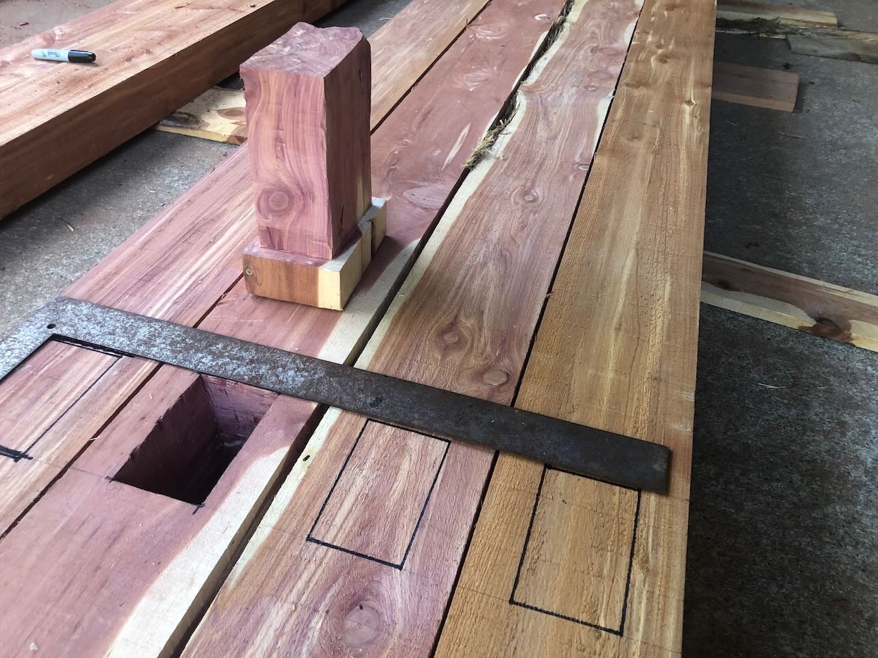
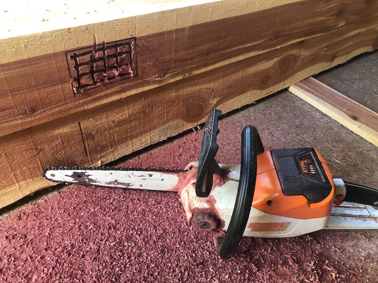
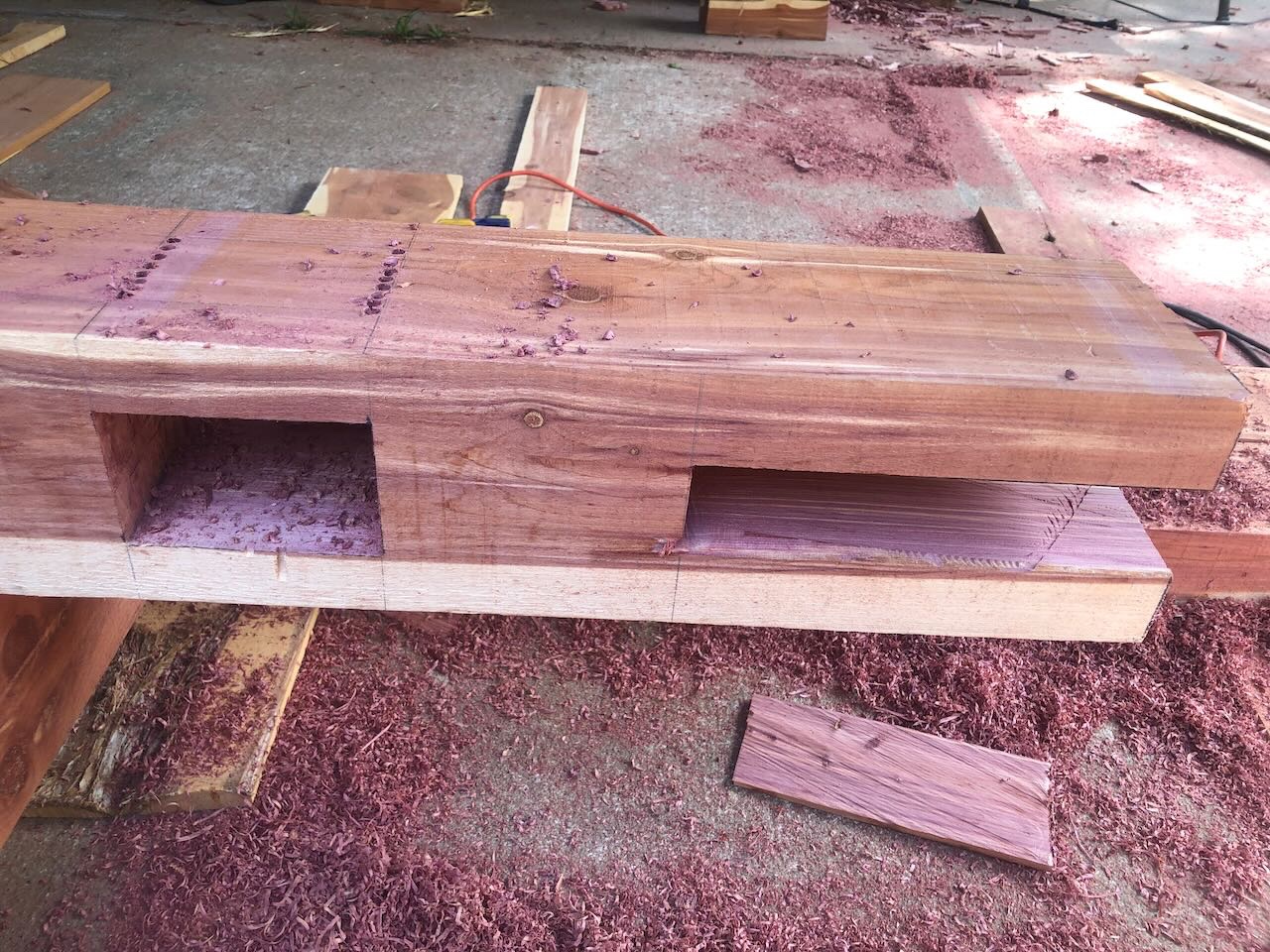
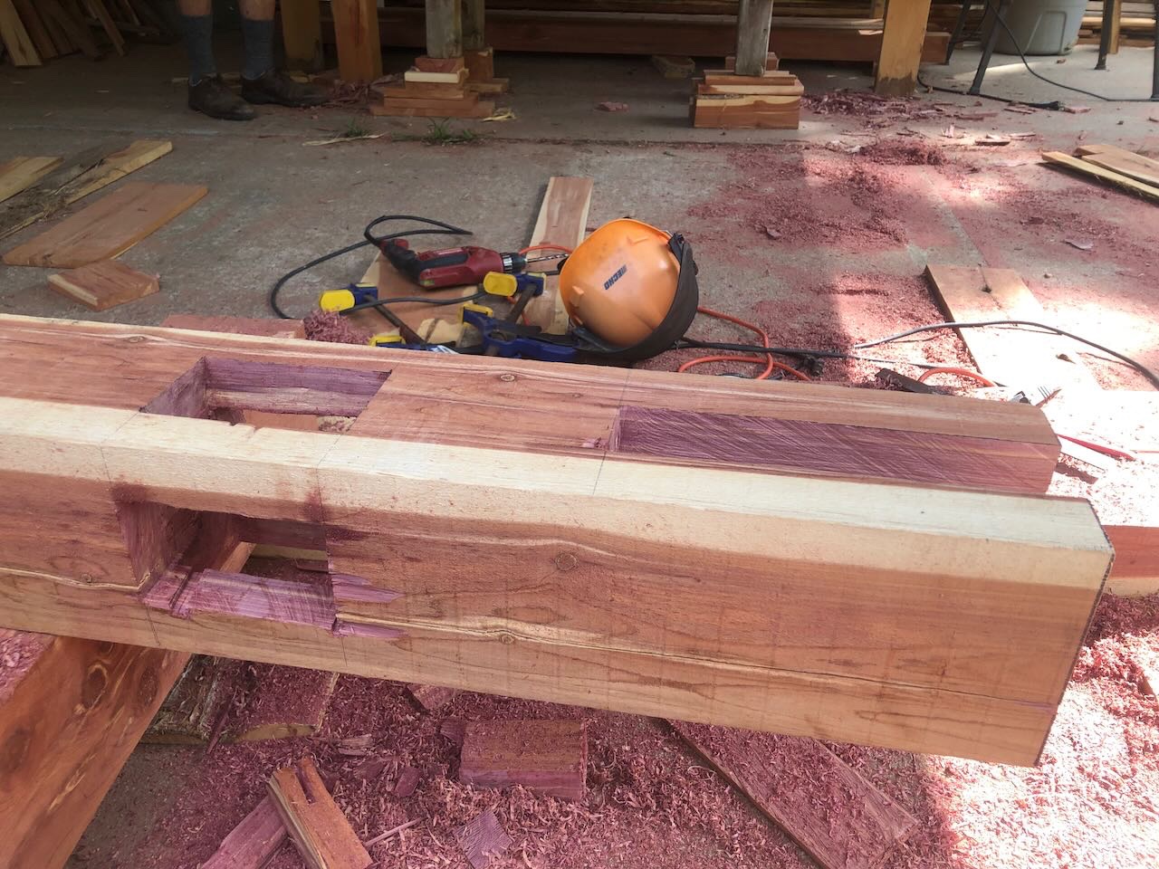
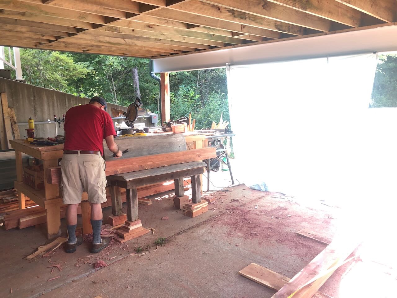
Yes, the purlins are notched into the rafters. If you look close enough at the plans you can see it but that image is pretty small. I want a smooth surface up there to attach the metal roofing to. We're pretty independent by normal standards, but we're not survivalists. We just value independence and quality of life. Certainly we were well set up to handle the last few years. Apologies, I completely forgot you had a long history here. Should've remembered. Thanks to all of your for your comments, likes, and interest. Day 1 OK, back to the project. On Sunday we did some preliminary planning but today we dove into the real work. It was a scorcher of a day, reaching 98º and shattering the old record high of 94º, and we were very grateful to be working in the shade under the outdoor porch. The first step was cutting four 6x6 posts and cutting out the mortises where the 4x6 crossbeams would go. I marked the corners and parts of the edges with a drill, then cored out the mortises with my electric chainsaw and finished them with chisels. We also made a test plug out of scrap 4x6, cut down to a tenon, to test each mortise. The next two images show the first one, which required a lot of chiseling. After this I cut a lot closer with the chainsaw, requiring less chisel work. I have a pretty steady hand with this saw and can cut near as accurate as a circular saw (another sign that my wrist has healed, even if it persists in being stiff and sore). The next step was to cut a 2x10 notch at the top of each post, into which the cross beams will drop once the frames are erected. Again, I cut these with the chainsaw and we finished them with chisels. I also achieved some epic dumbassery during this step; can you identify it in the photo below? That's right, I cut the 2x10 mortise 90º off; it's supposed to go in the opposite direction to the other mortise, not parallel to it. Oopsy-woopsy. We decided the best way to fix this was to re-cut the 4x6 mortise, since re-cutting the 2x10 would leave four narrow unsupported columns at the top of the post. You can see a few drill holes where I started to lay this new mortise out. Here's the "fixed" post: Memo to self: it's "measure twice, cut once", not the other way around. This is the only solution since we only have four posts; the downside of logging and milling everything yourself is you can't just run to the lumberyard for a new post. I did have a fifth post milled but it's not very good quality (turned out to have internal flaws we couldn't see until after milling) and I'd rather keep this one. The current plant for hiding that ugly cross-mortise is a combination of plugging the hole with scrap wood and/or running a thin sheet of cedar over that location on all four posts to look like decorative flair. I've used decorative details to hide mistakes in models, too, so this is no different! As the afternoon sun crept into our west-facing workspace, it got hotter and the glare started messing with my stepfather's cataracts, so I hung a sheet from the porch support beam, which worked great! We didn't quite finish the posts, in part because I need to recharge the chainsaw, but they'll easily be finished tomorrow. I started on the first of two 4x6 crossbeams, cutting the tenons with a circular saw and cleaning them up with a chisel: Tomorrow we'll try to finish the post-crossbeam mortises and the crossbeam tenons, then assemble one post/crossbeam frame so we can lay out the locations of diagonal braces and start cutting the mortises and tenons for those (which will be smaller, but also need to be accurate so the frame stays square). We also need to start cutting the central mortise on the crossbeams that will hold the kingpost. Lots of work left to do, but it feels like we made good progress today. A long cold shower felt amazing after being caked with sweat and sawdust. We'll enjoy our on-farm dinner of tacos made with homegrown corn, stuffed with on-farm beans, tomatoes, greens, etc., and a sourdough pear galette using orchard fruit. Tomorrow's forecast as another scorcher at 96º, but if we survived today I think we can handle it. On Wednesday a strong cold front sweeps through, and by Thursday our high is forecast a full 30º lower, at only 66º! That's more like it for we two Great Lakers.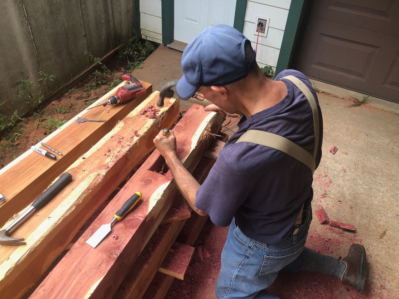
- 131 replies
-
- 10
-
-
Timber-framed outdoor kitchen - Cathead - 1:1 scale
Cathead replied to Cathead's topic in Non-ship/categorised builds
I just realized that I forgot to clarify an important point for this project, which I'd mentioned in my current build log for USS Cairo and thus forgot to restate here. The timing of this project relates to a visit from my stepfather, a lifelong (but now mostly retired) professional woodworker who is an absolute artisan with wood. You can find his work in various artisan galleries around the New York Finger Lake and Adirondacks. We planned his visit so the two of us could build the kitchen together, as it overlaps our skill sets; I'm more used to rough large-scale construction but he's a genius with joinery and other careful hand skills. I can trace a lot of my knowledge and enthusiasm for building things back to coming of age around his workshop, and it'll be really meaningful to build this structure with him. He's fascinated by my model-building and has never tried it, though he recently built himself a 1:1 rowboat that he designed himself. Here we are in his shop back in 2021, with the recently completed vessel: So it's going to be super-neat to spend the next couple weeks working together on this project.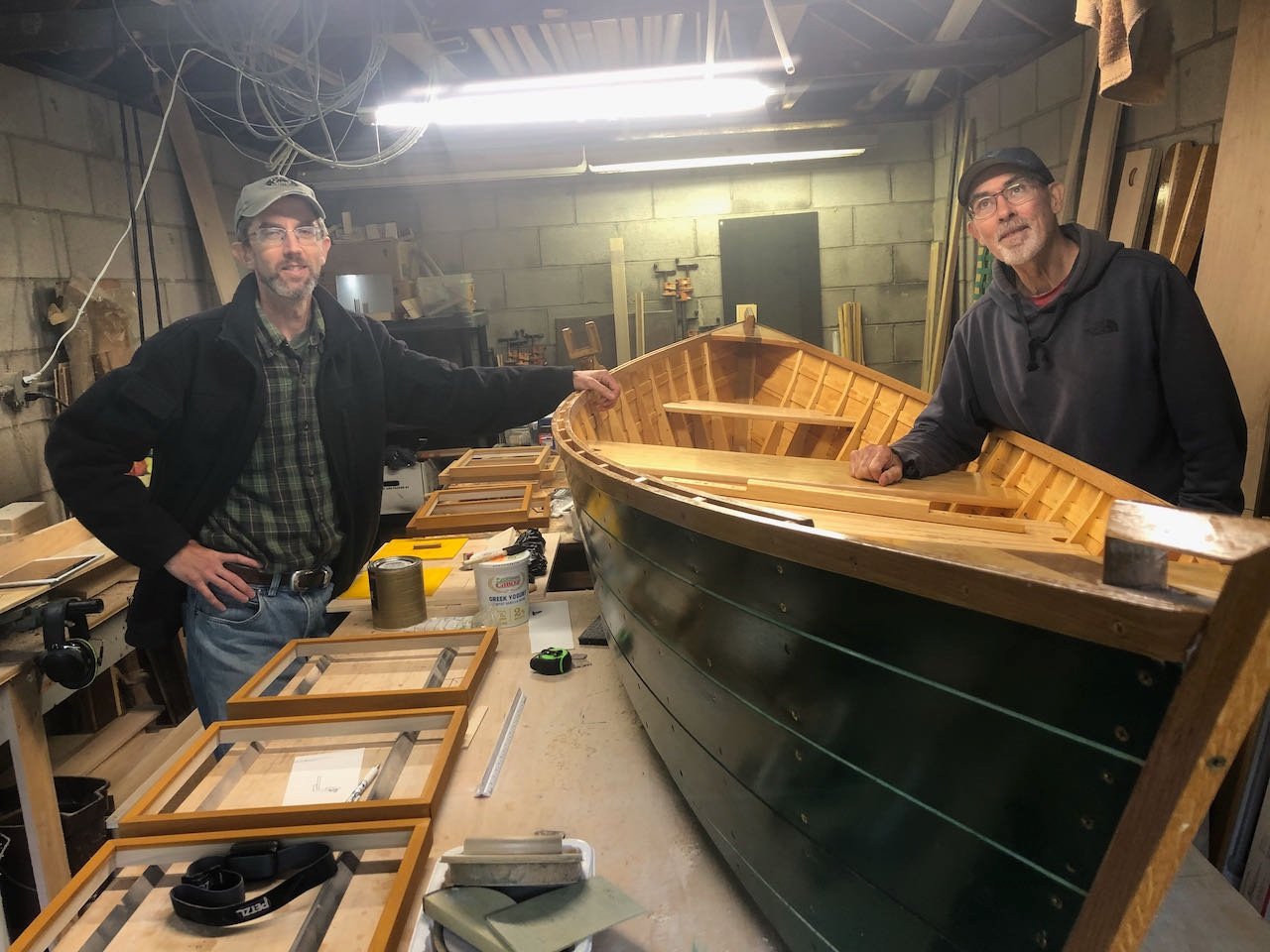
- 131 replies
-
- 14
-
-
Timber-framed outdoor kitchen - Cathead - 1:1 scale
Cathead replied to Cathead's topic in Non-ship/categorised builds
Mark, the local Native American history is a lot richer than commonly understood. By the time of active white settlement (1800s), populations had collapsed due to widespread introduction of European diseases and wars caused by ongoing displacement of more eastern tribes. Many of the cultures we think of as "Plains" Indians actually started out along the Great Lakes and other more eastern regions and were pushed westward by the wave of Euro-American settlers. For example, the Osage, the most commonly known Missouri tribe in the modern era, started out in the Kentucky portion of the Ohio River valley and steadily had to move west to get away from Euros. They resettled in Missouri and Arkansas for a while, developing new cultural traditions to adapt to that significant change in setting, then were pushed west again to Kansas and Oklahoma. There are copious burial mounds on blufftops along the Missouri River and well inland from the river, evidence of past complex societies and dense populations. It's easy to forget that Native American history here spans thousands of years, not single tribes, with rises and falls just like European history. So the points and tools we find cover a pretty wide spread of cultures, like finding Greek, Roman, Celtic, and Ottoman artifacts in a given site. The earlier mound-building cultures that erected Cahokia and other extensive cities along the Mississippi date back hundreds to thousands of years before modern "discovery", and also likely collapsed due to disease spread ahead of widespread settlement. The most recent native inhabitants in Missouri, the Osage, followed a semi-nomadic pattern in which they cleared and planted crop fields in established settlements, then left for long buffalo/game hunts, returning now and then to weed and tend the crops, then settled into winter quarters. But they weren't here long enough to really be representative of longer-term local practices or cultures, any more than the Normans were representative of deeper British culture in 1100. They're only the most recent veneer on a much deeper set of cultures that have passed through and inhabited this area.