G.L.
-
Posts
1,553 -
Joined
-
Last visited
Content Type
Profiles
Forums
Gallery
Events
Posts posted by G.L.
-
-
-
Thanks for your appreciation, Ward.
It is the moment to make the most important equipment of a 18th century warship: the artillery.
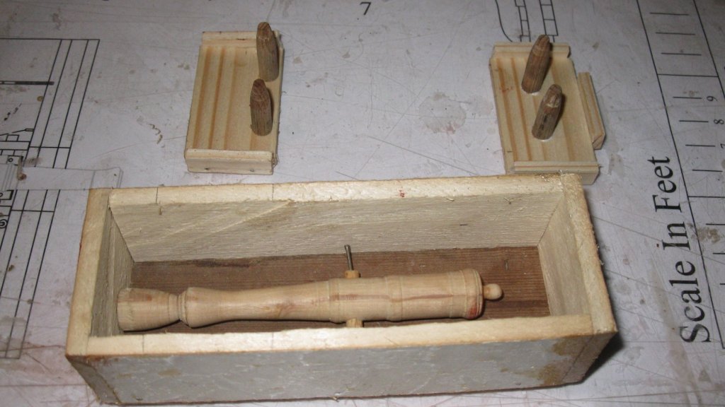
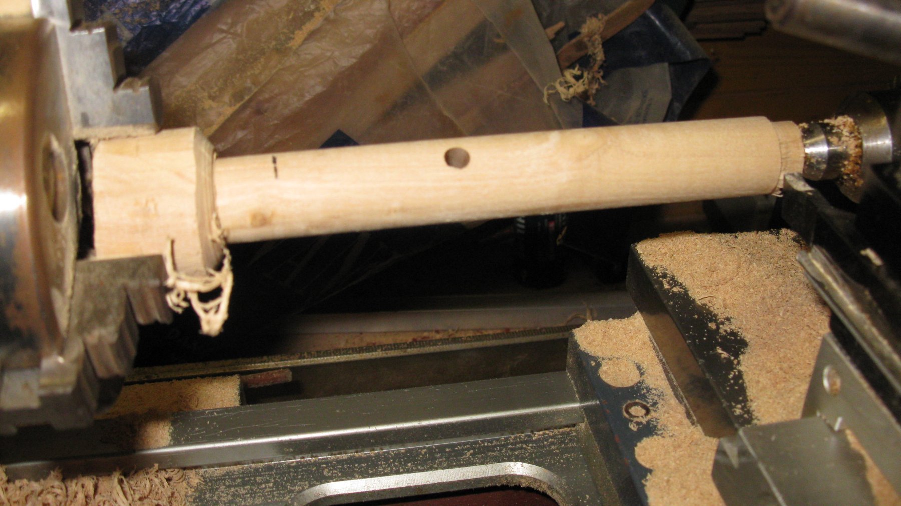
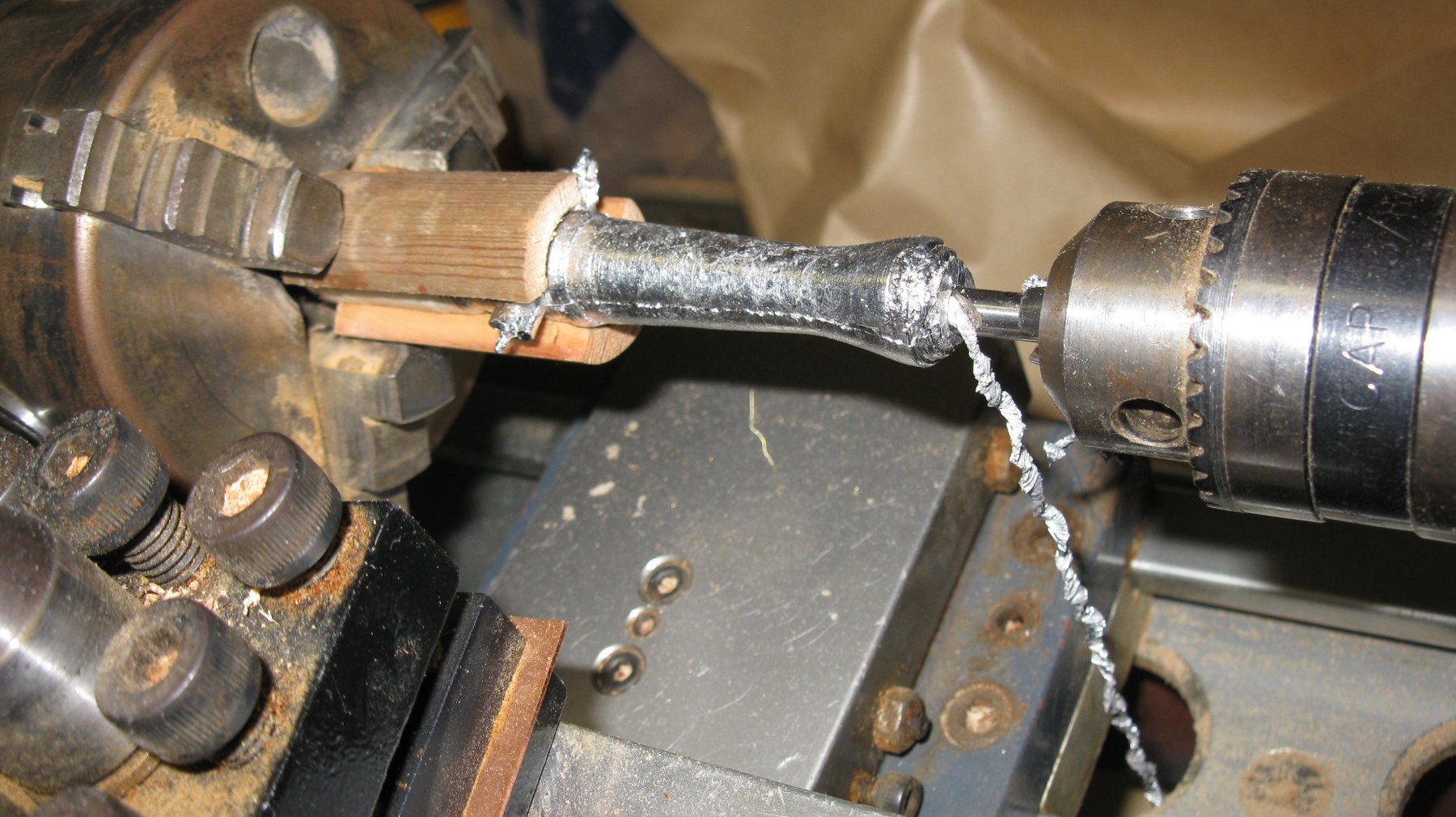
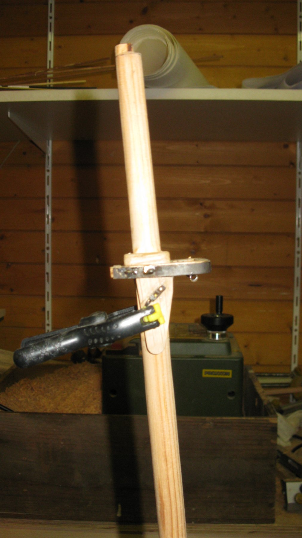
I want to cast the gun barrels in tin. To make the casting mold, I turn a model of a gun barrel in wood. I start with drilling the hole for the trunnions next to the center line of a piece of olive wood.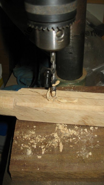
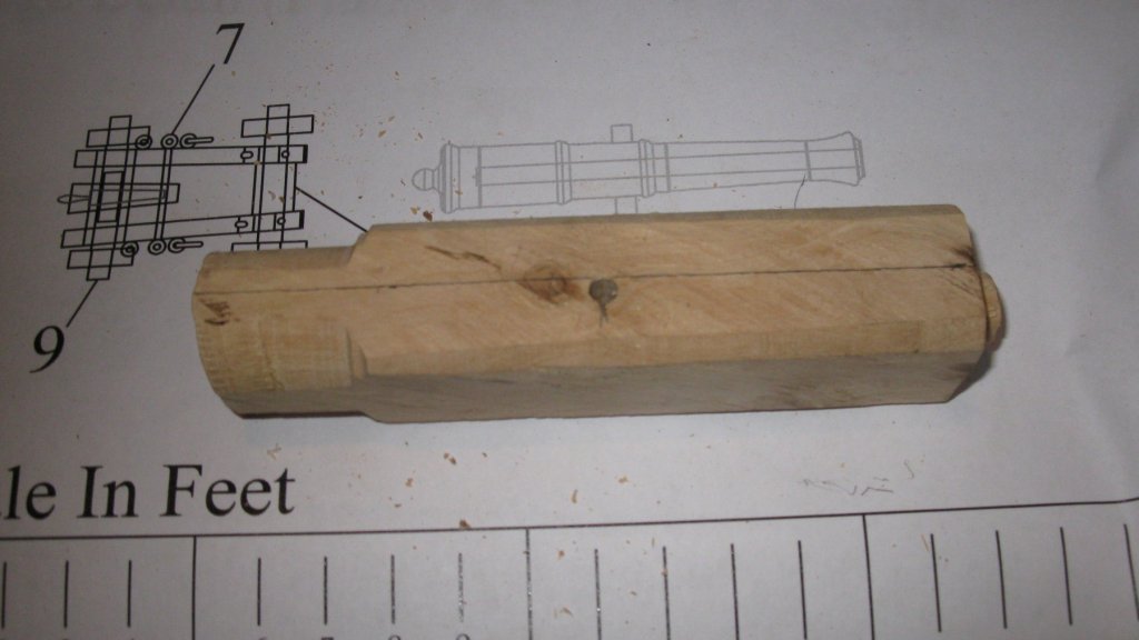
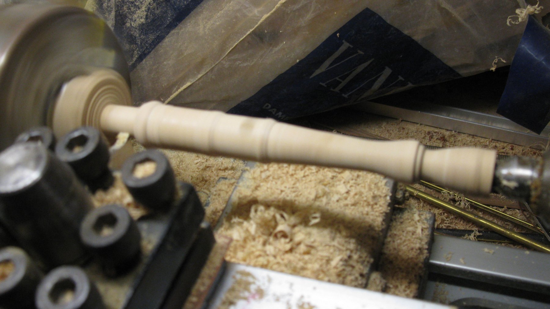
Then I turn the barrel in accordance with the plan.

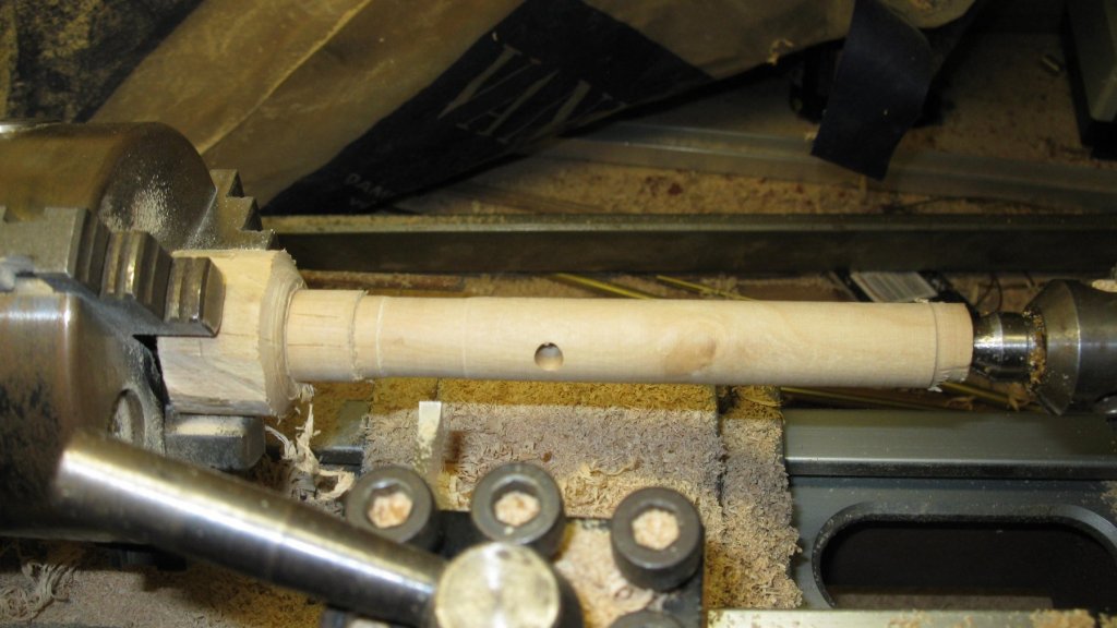
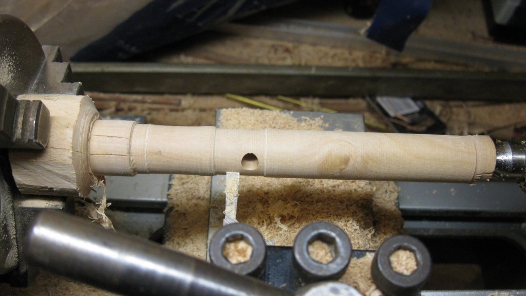
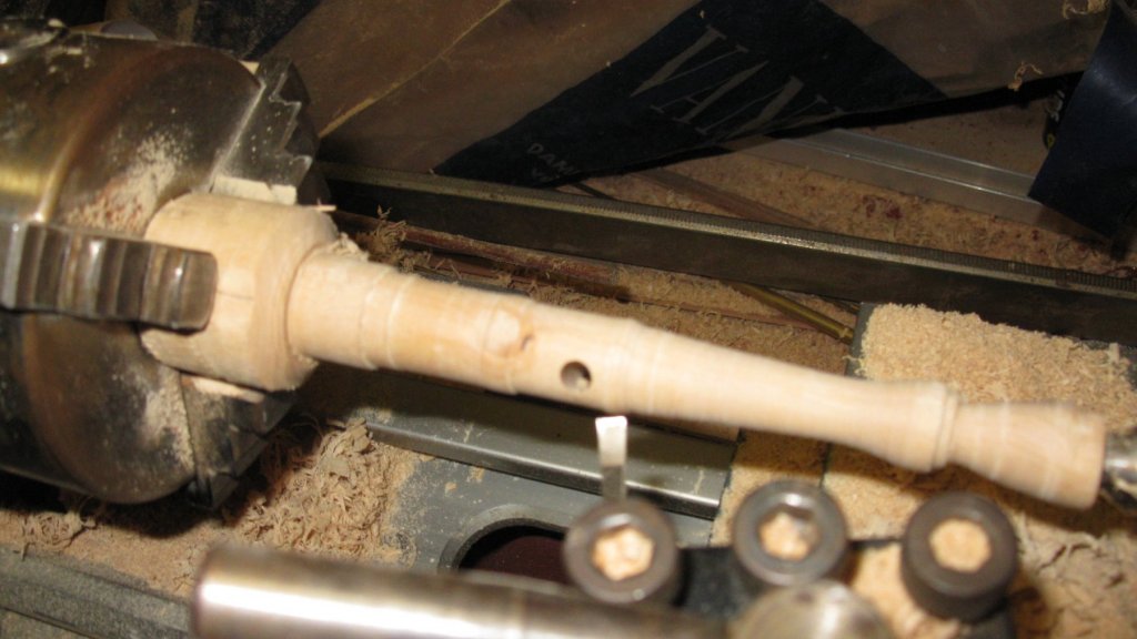
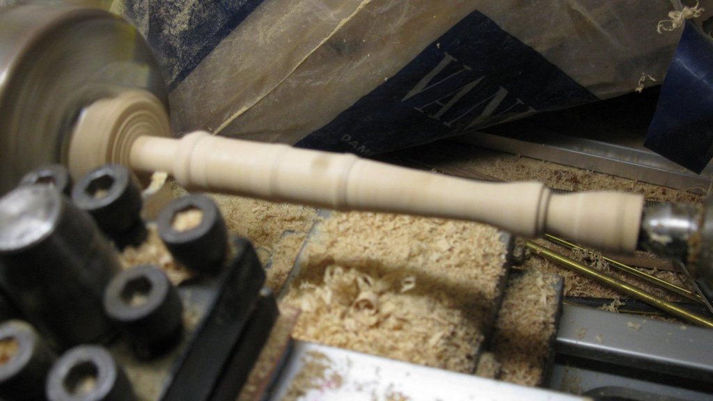
I leave a funnel-shaped appendix at the gun mouth. It will form the pouring opening in the casting mold.
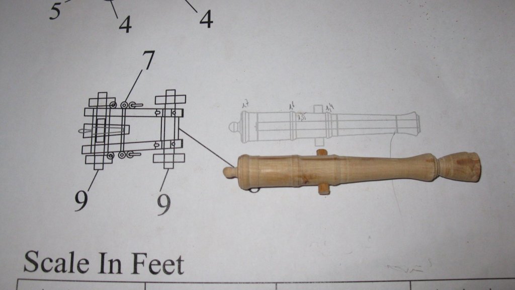
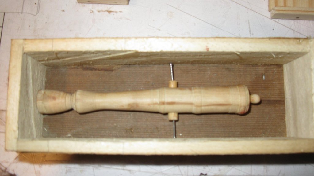
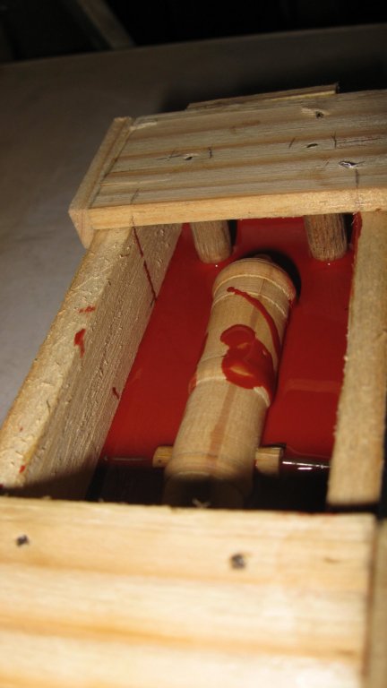
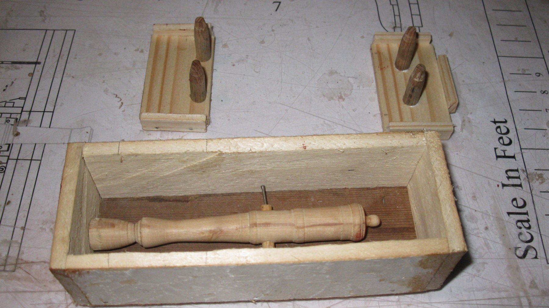
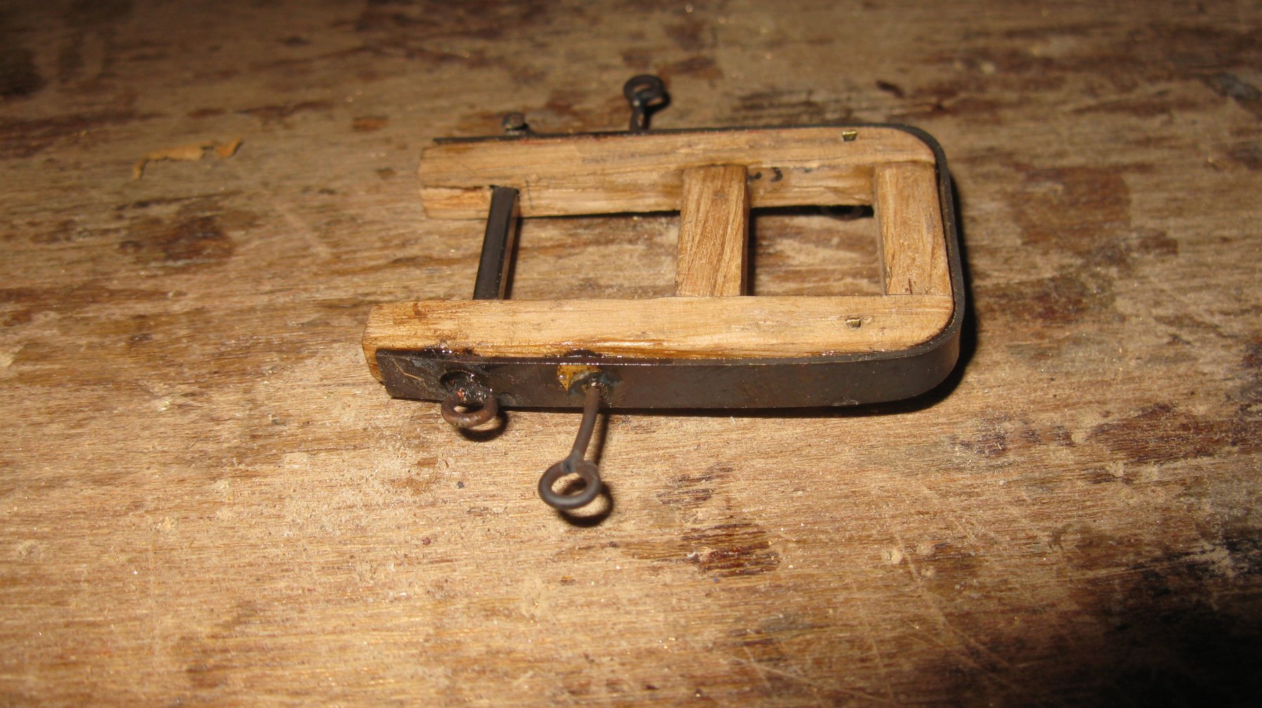
The mold will be made in a small wooden box in which fit the gun model. The purpose of the two small planks with the conical wooden pins next to the box will become clear soon. The two nails in the trunnions keep my gun model in the middle of the box and will also make two air tunnels in the mold through which the air can escape when pouring the melted tin in the mold.
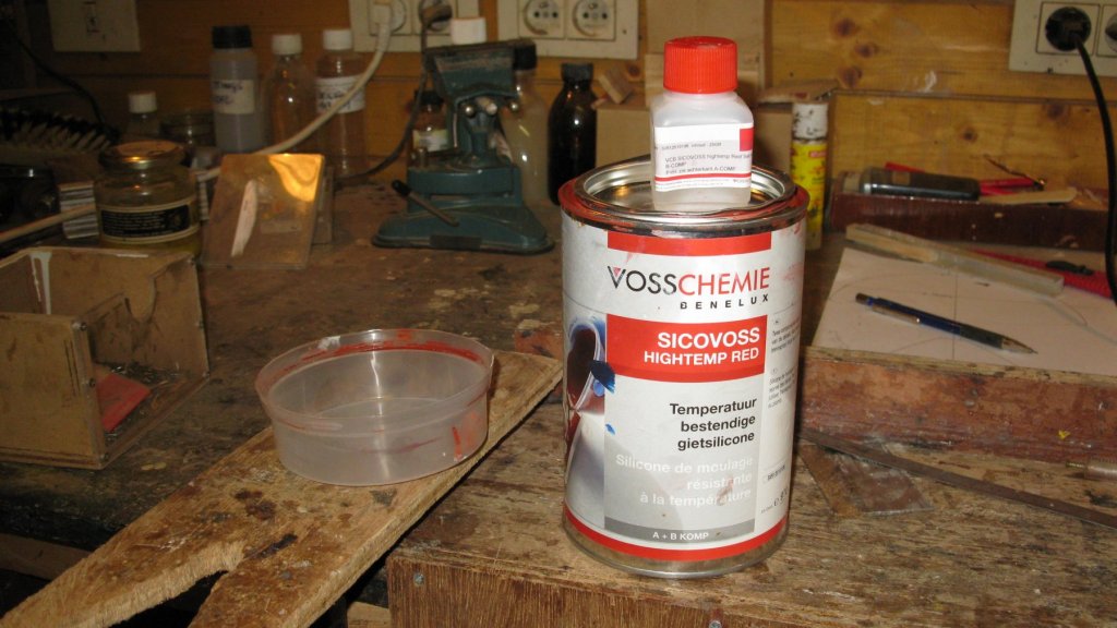
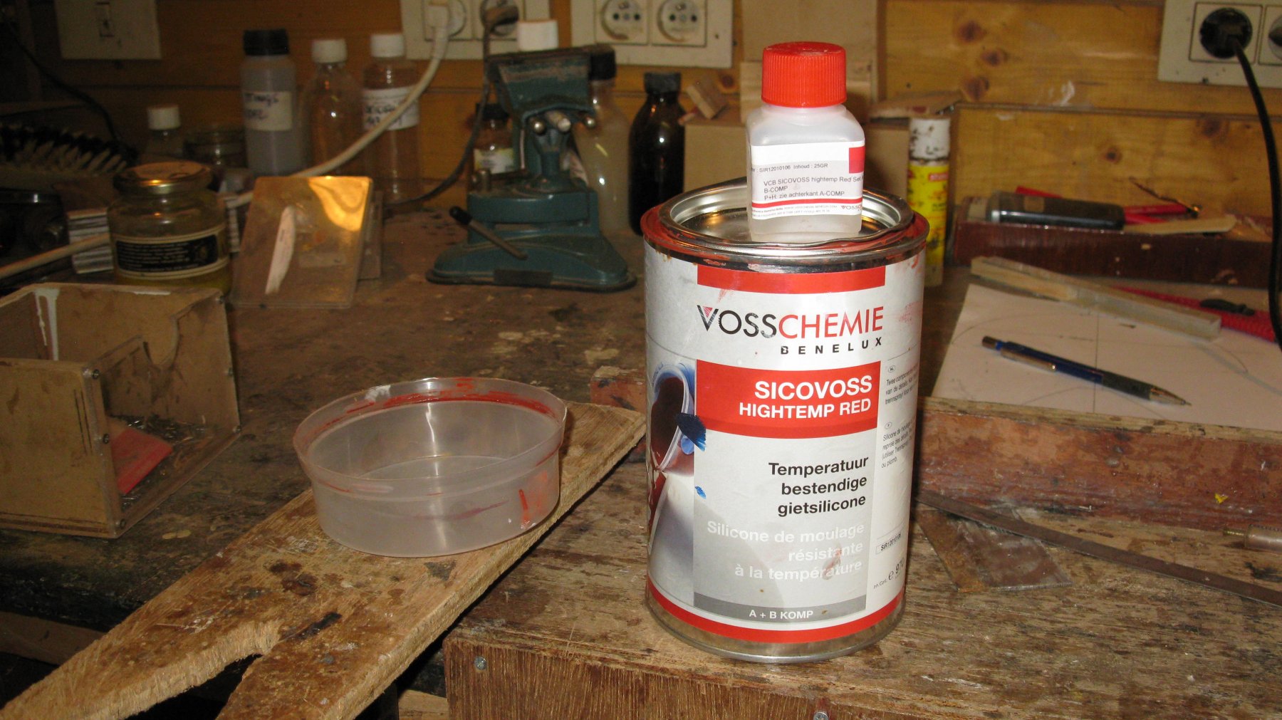
The mold will be made with a heat resistant silicone. It consists of a red colored raisin which has to be mixed with 2.5% hardener.
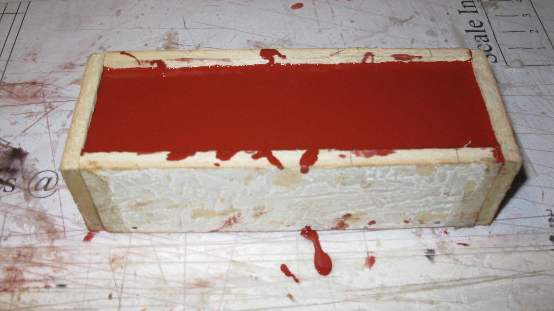
My box has a volume of about 22 cl. I start with making 10 cl of silicone and pour it in the box. I press the gun model in the silicone until it sits approx. halfway in the fluid.
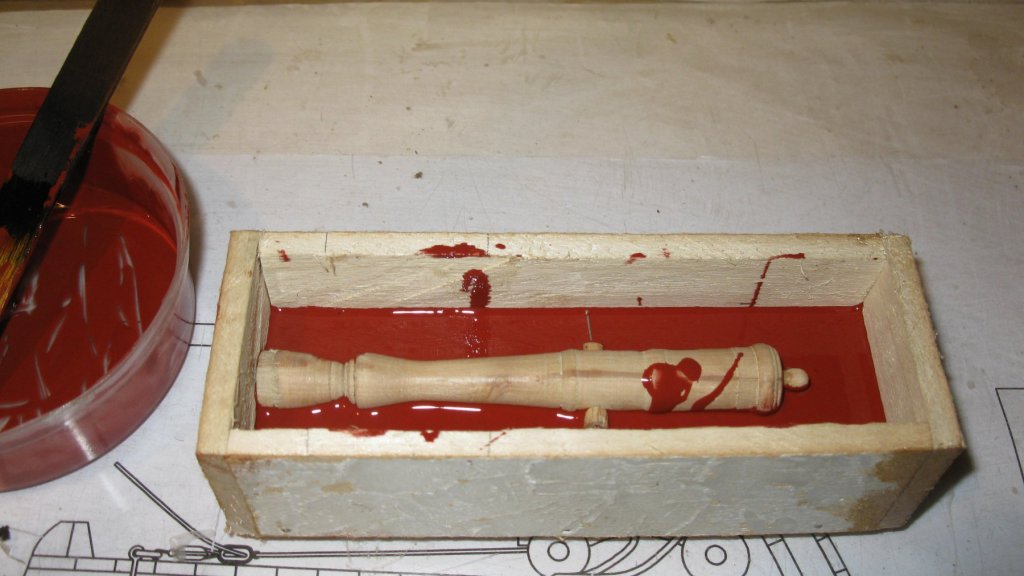
I lay also the two planks with wooden pins on the box in such a way that the tops of the pins are sitting in the silicone.
A day later the silicone is hard (or soft like rubber) and the pins can be removed. They form four conical holes in the top of the bottom half of the mold. All silicone spills on the wooden gun model are removed. I spray some release agent on it.
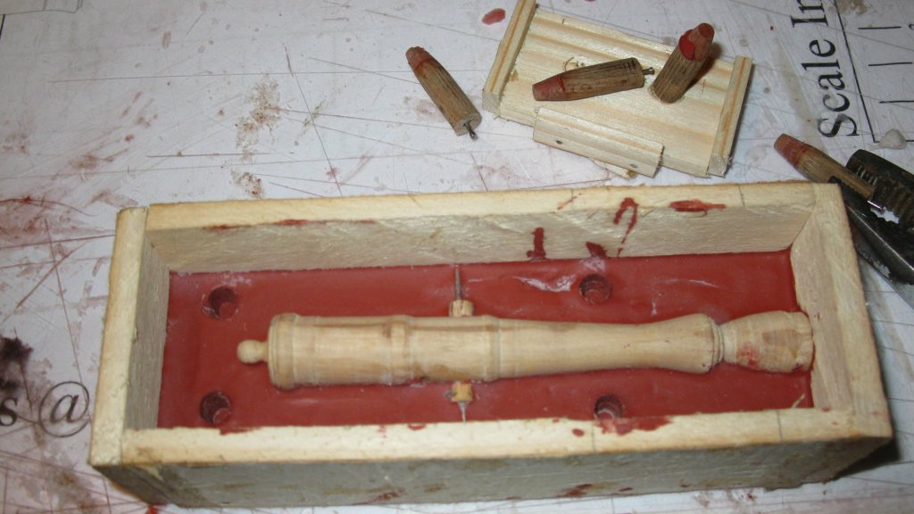
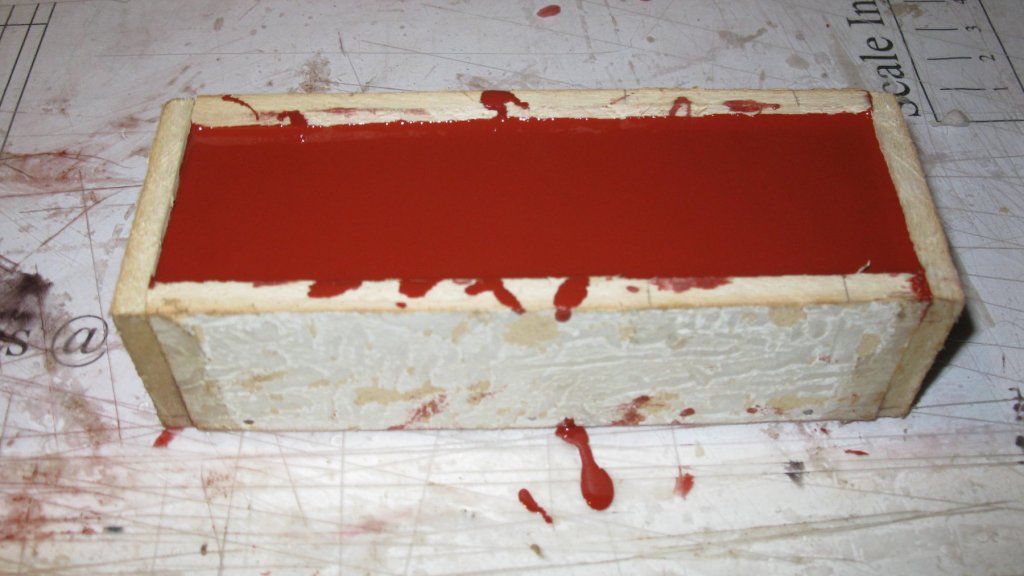
Now I mix again 10 cl silicone and fill the box.
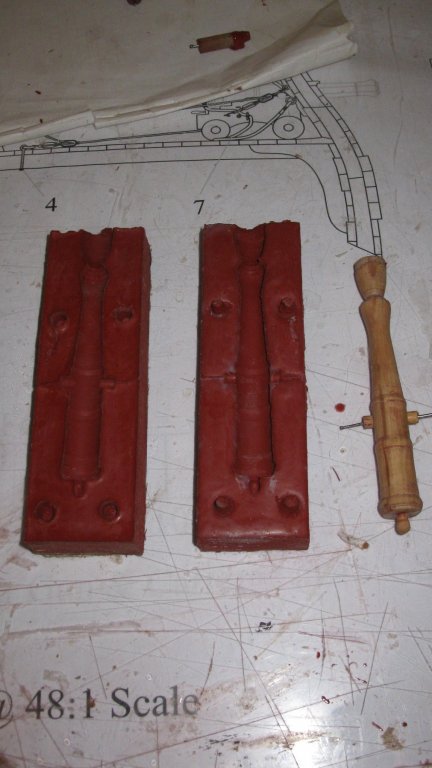
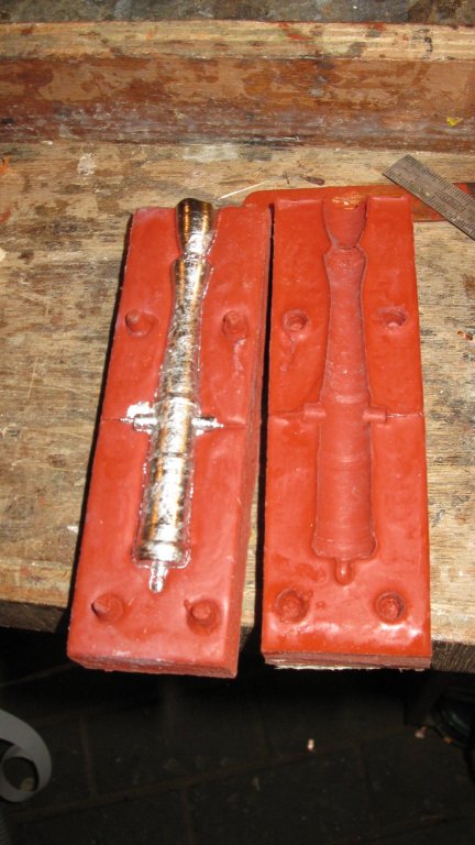
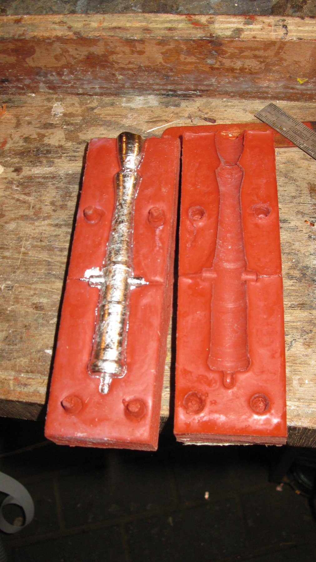
A day later the mold can be dismantled and the two halves can be taken token apart. In the bottom half of the mold are the four pits of the wooden pins and in the upper half four protrusions which perfectly fit in them. They make it possible to join the mold perfectly.
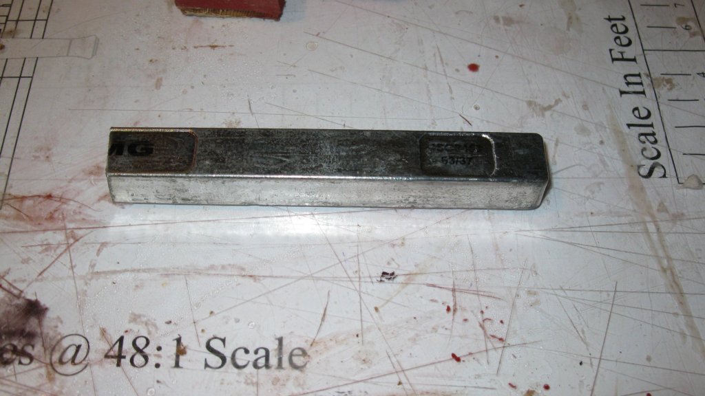
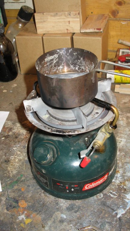
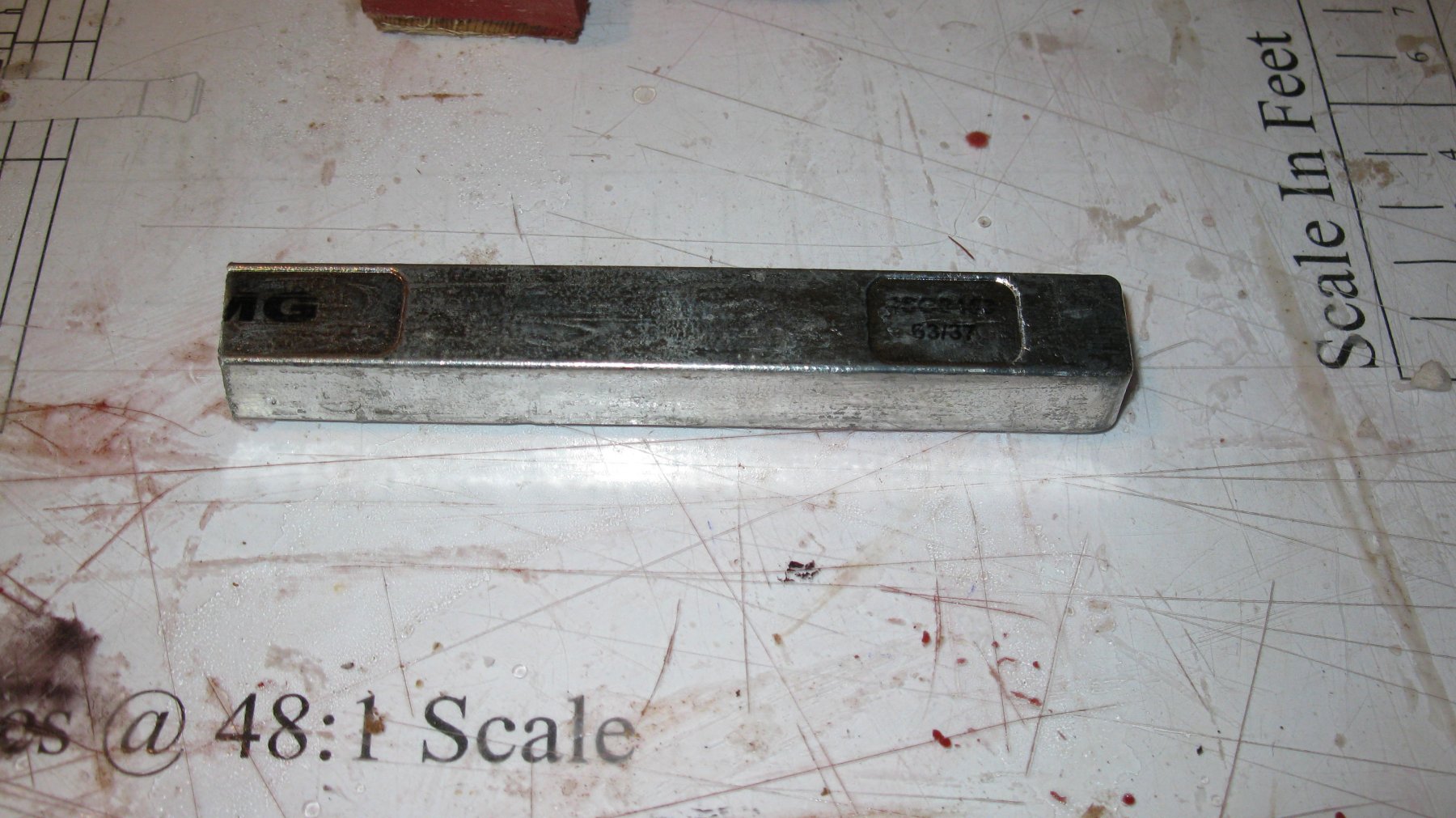
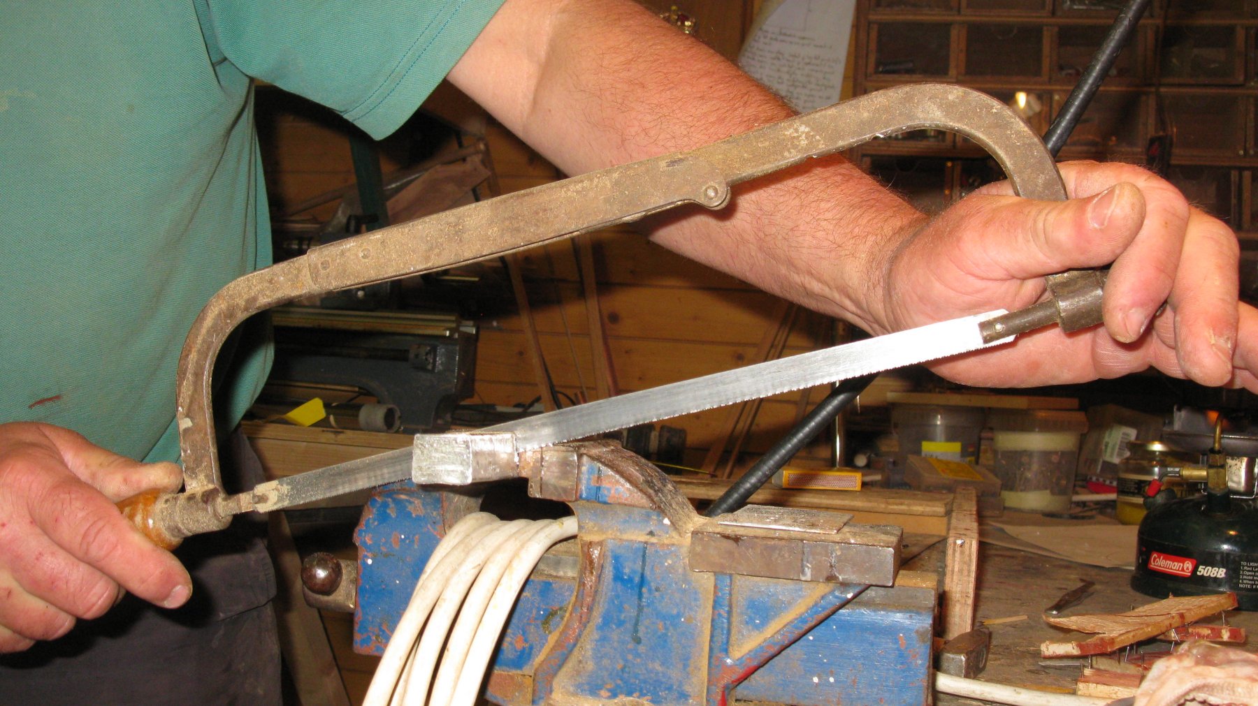
I use tin for plumbers to make the guns. It is sold as rods of about 30 cm long, pieces can be sawn of with a metal saw. My melting furnace is a simple spirit fire and a small sauce pan.

The melted tin is poured in the mold.
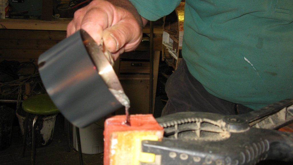
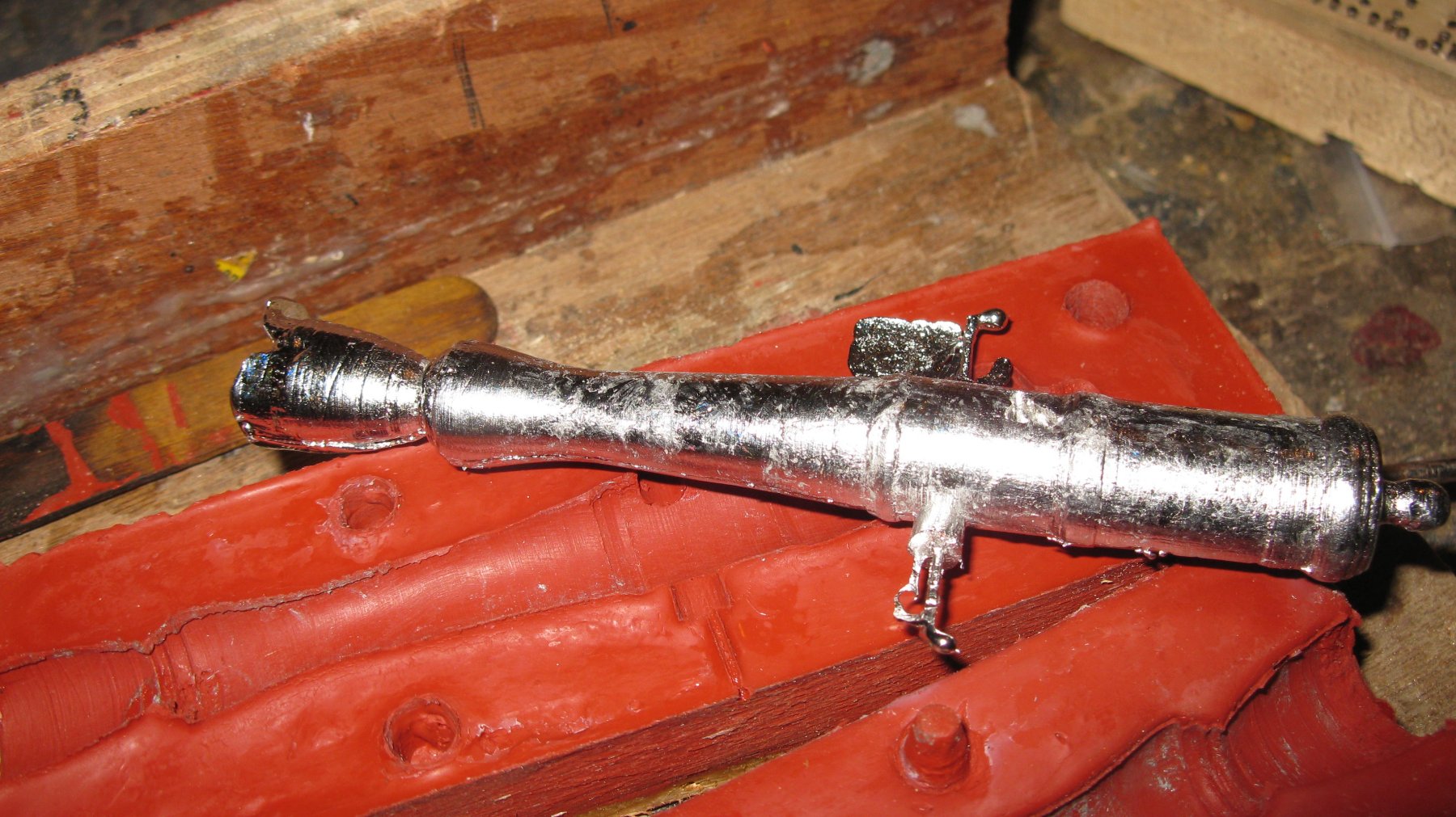
Some ten minutes later the mold can be opened. Be careful because although the tin has solidified, it is still very hot.

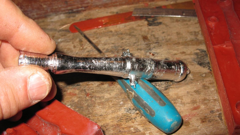
The pouting funnel is sawn of and I drill out the mouth of the gun.

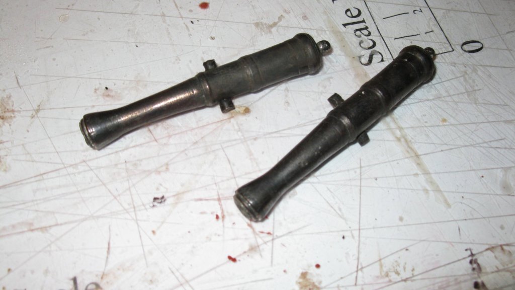
All the mold seams are filed and the barrels are blackened.
- Pete38, Mike Y, jablackwell and 11 others
-
 14
14
-
-
-
Thank you very much Aviaamator, I think I understand your method. I am grateful to you that you wanted to share it.
Many regards,
G.L.
- mtaylor and aviaamator
-
2
-
-
Aviaamator,
I will follow your sail making with lot of interest because I am preparing to make sails for my shrimper as well. I have also never worked with a sewing machine. I could certainly use an assistant like Jung.
The small metal rings to sew around the holes seem me very handsome. Can you show how you put them in place?
I wish you a speedy recovery,
G.L.
- aviaamator and mtaylor
-
2
-
-
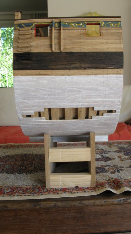
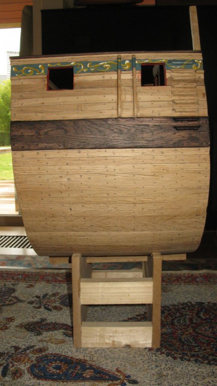
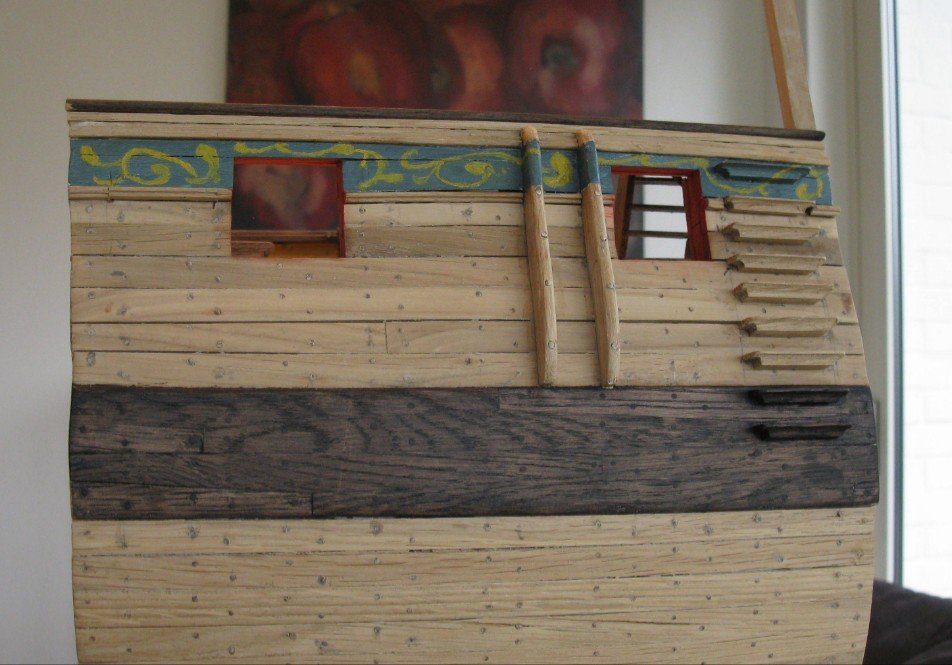
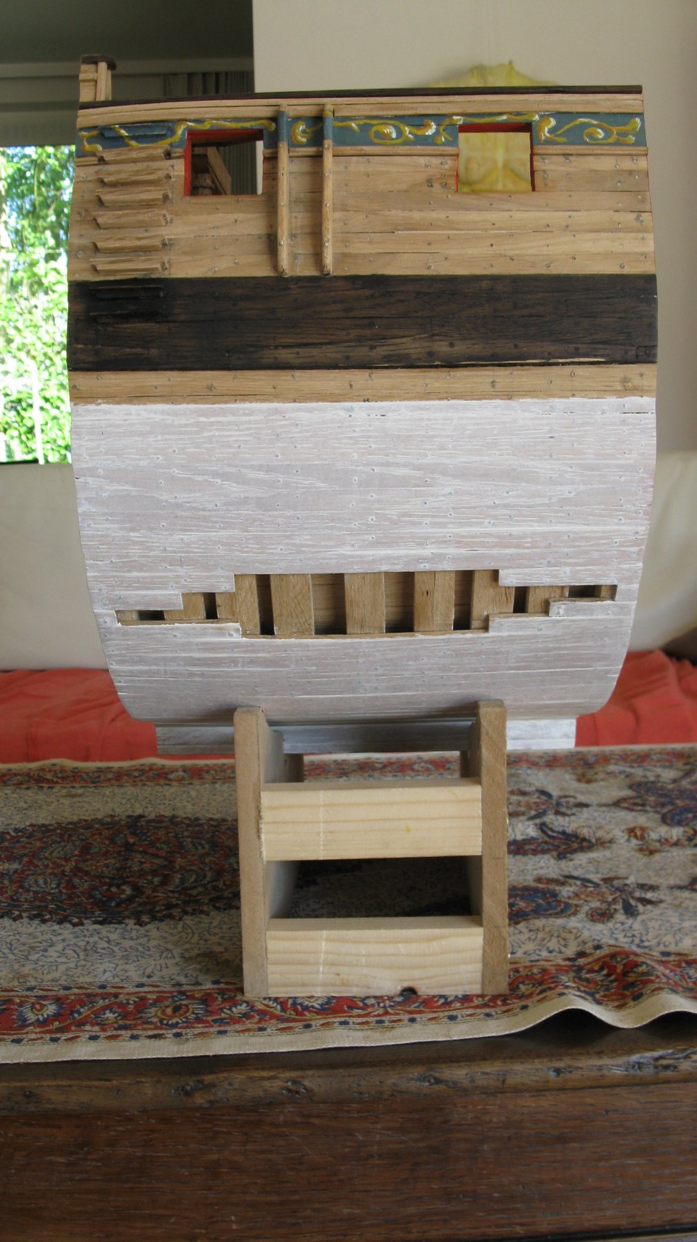
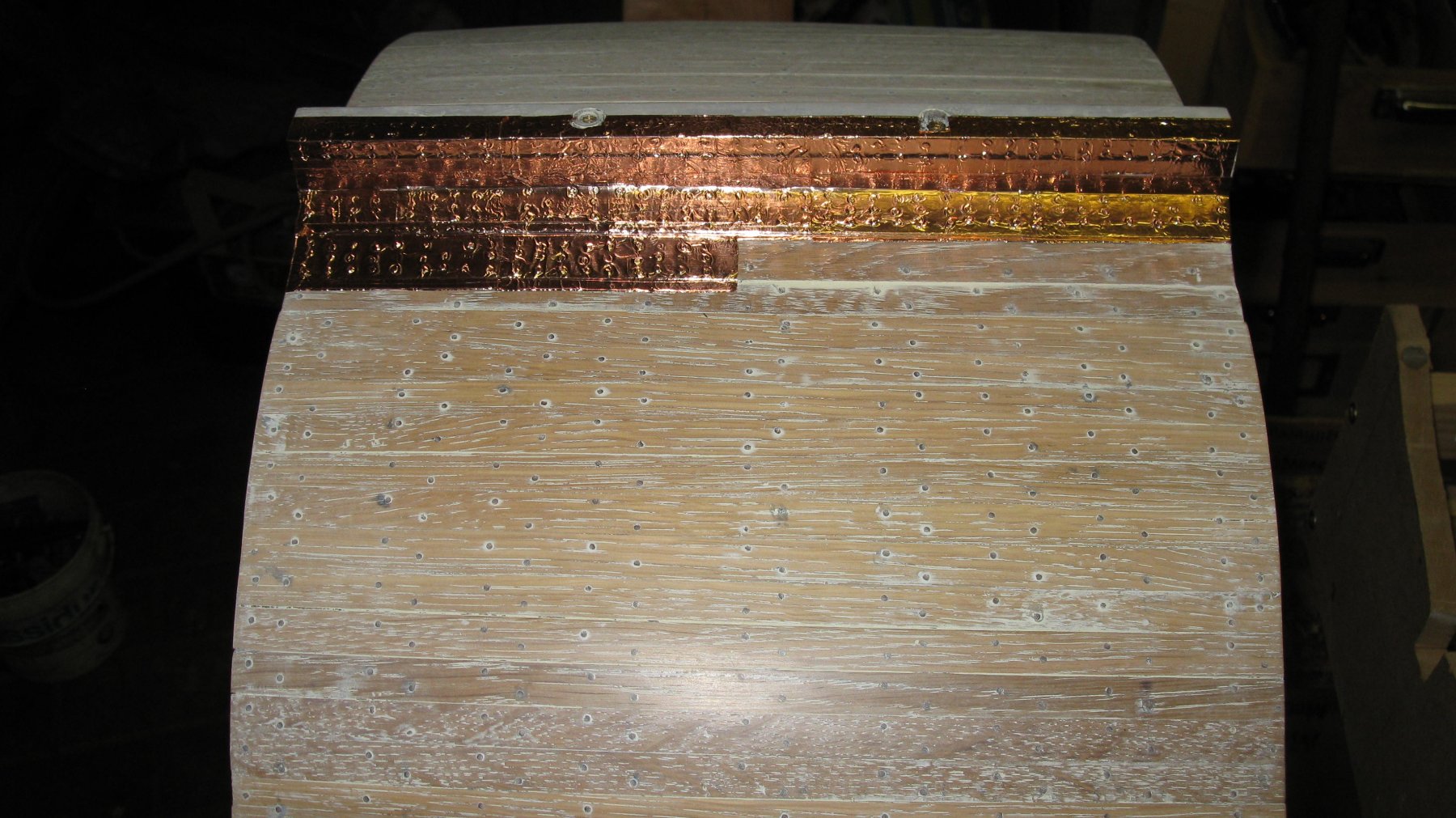
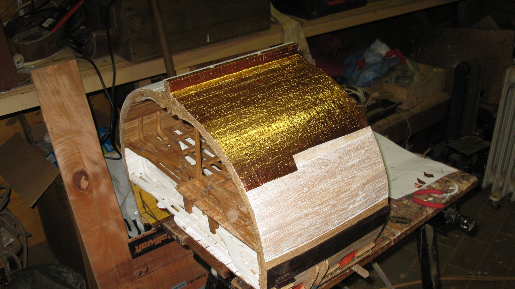
I read on this forum that the Mermaid class frigates underwater hull were painted with white stuff and later (for HMH Triton in 1779) were coppered. Some of the cross section builders show both versions, one side white and one side coppered. I decide to follow their example. Starboard side will be white and port side coppered. Here you see starboard side:
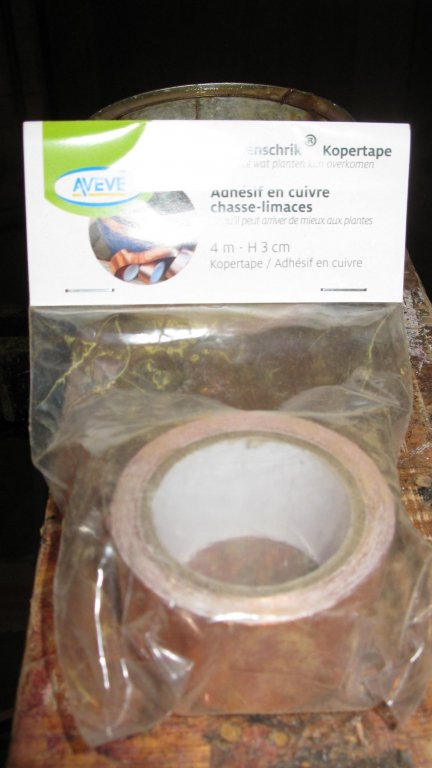
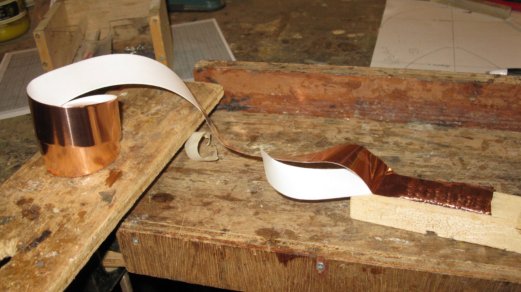
In our local garden center I found copper strips to protect vegetables in the kitchen garden against snails. It consists of a copper foil strip which is self adhesive. Probably effective against snails, but certainly effective for ship modeling.
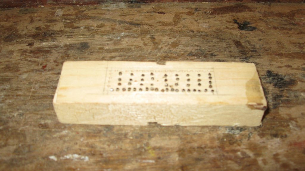
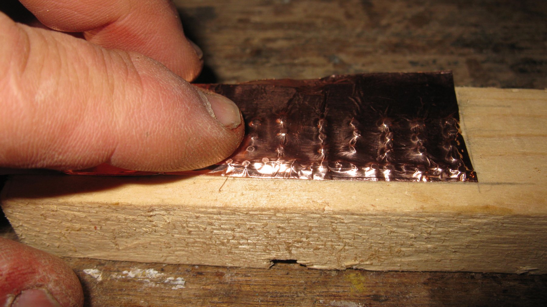
To obtain a nail pattern on my copper strips, I draw the pattern on a piece of wood and drill the nail holes (ø 1.5 mm).
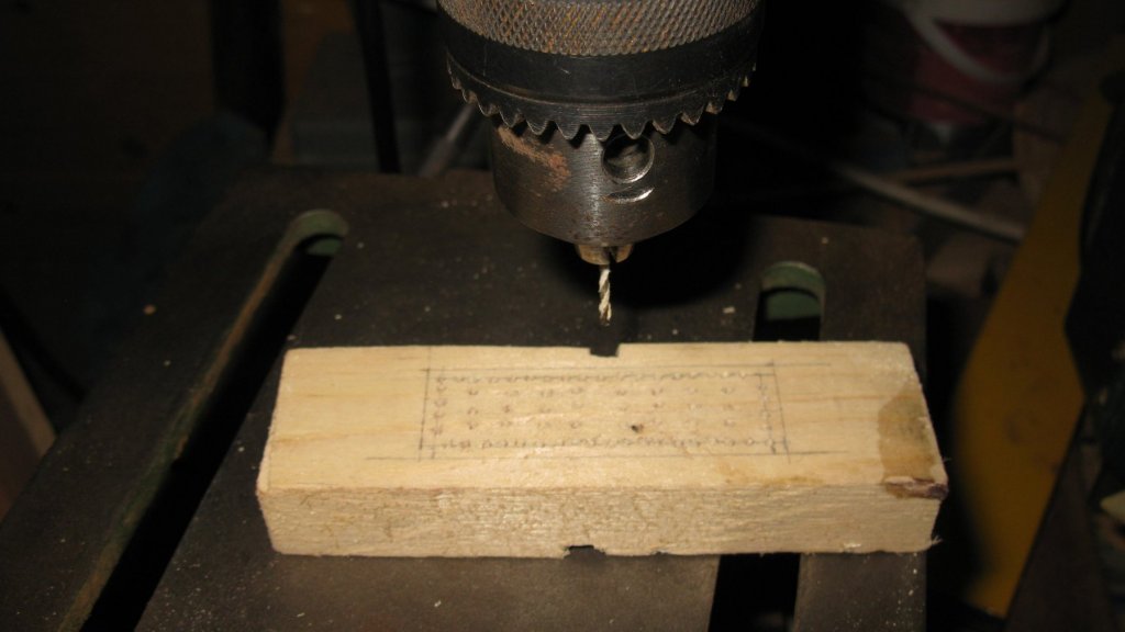
In each hole I put a 1.5 mm nail of which only the head sticks out of the wood surface. As I will glue the copper sheets from under to above and from aft to forward, I wait to place the nails of the upper- and left edge. They will be each time covered by the previous layer. When gluing the upper layer, the upper edge will be nailed as well.
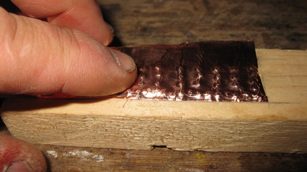
To imitate the nail heads on the copper plate, I lay the copper strip on the nail bed and rub with my finger over the copper sheet until the nail heads are embossed in the copper foil. Thereafter I cut the copper to the right dimensions, in this case 2x6 cm).

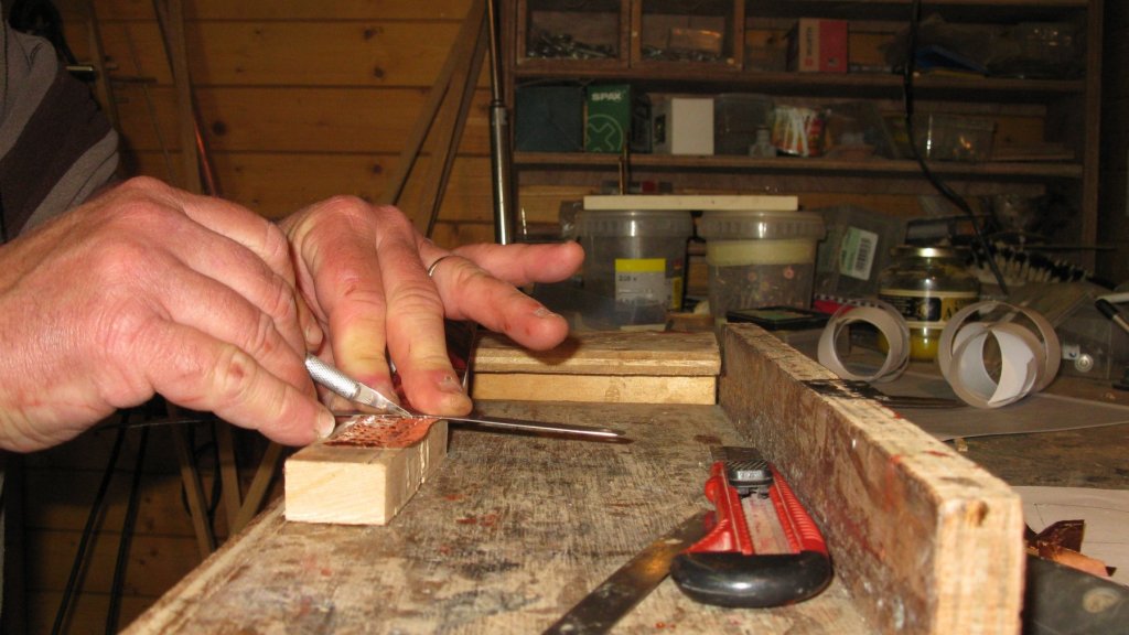
As the copper foil is self adhesive, the fixing on the hull goes easily.
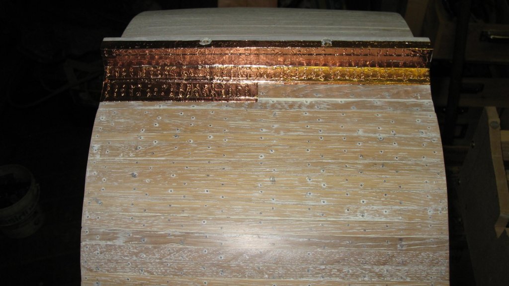

Coppering finished!
- Jolley Roger, Duanelaker, Canute and 6 others
-
9
-
-
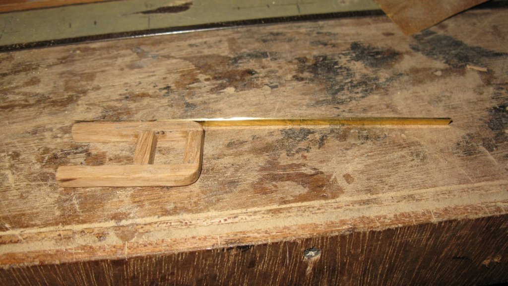
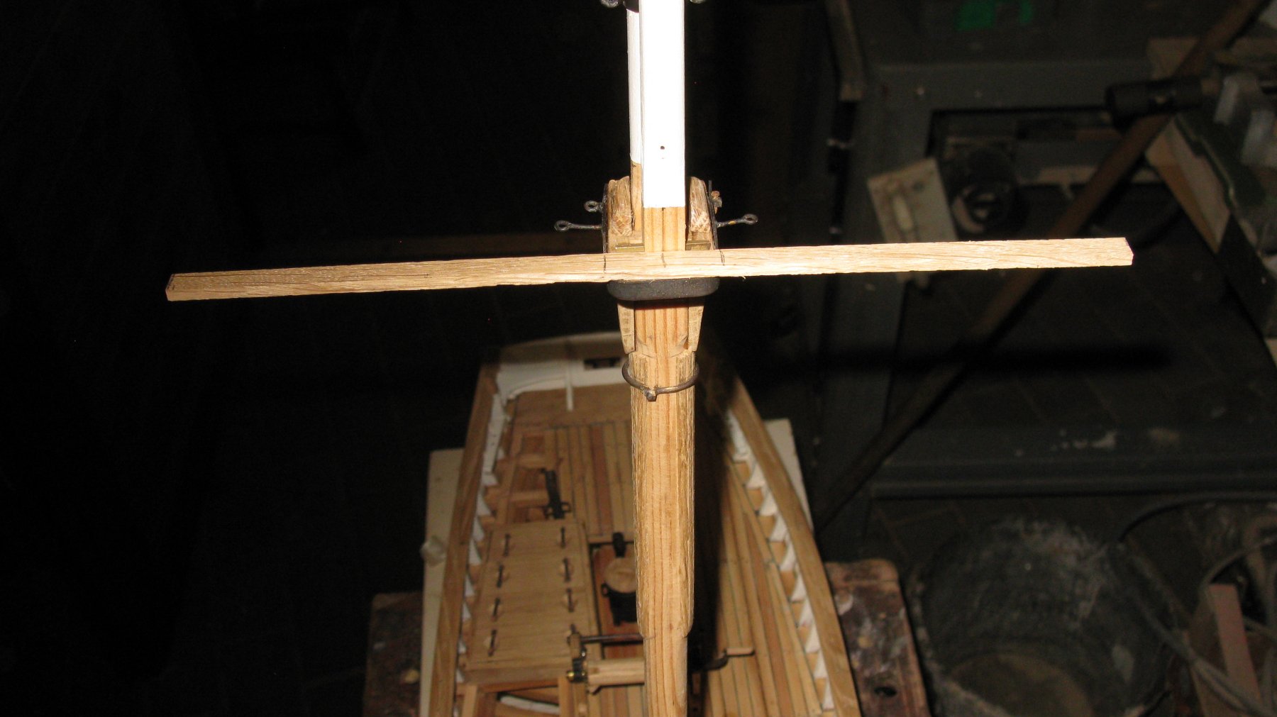
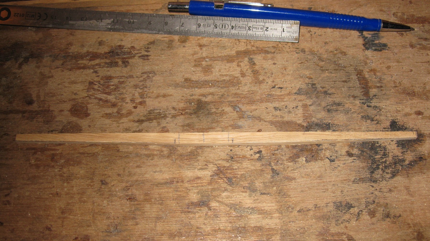
17.5 Mast. Spreader:
The spreader is as long as the ship is wide. Taking the measurements. On this picture, the maintop is already painted in white.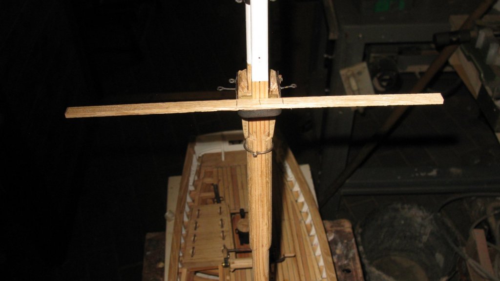
The spreader.

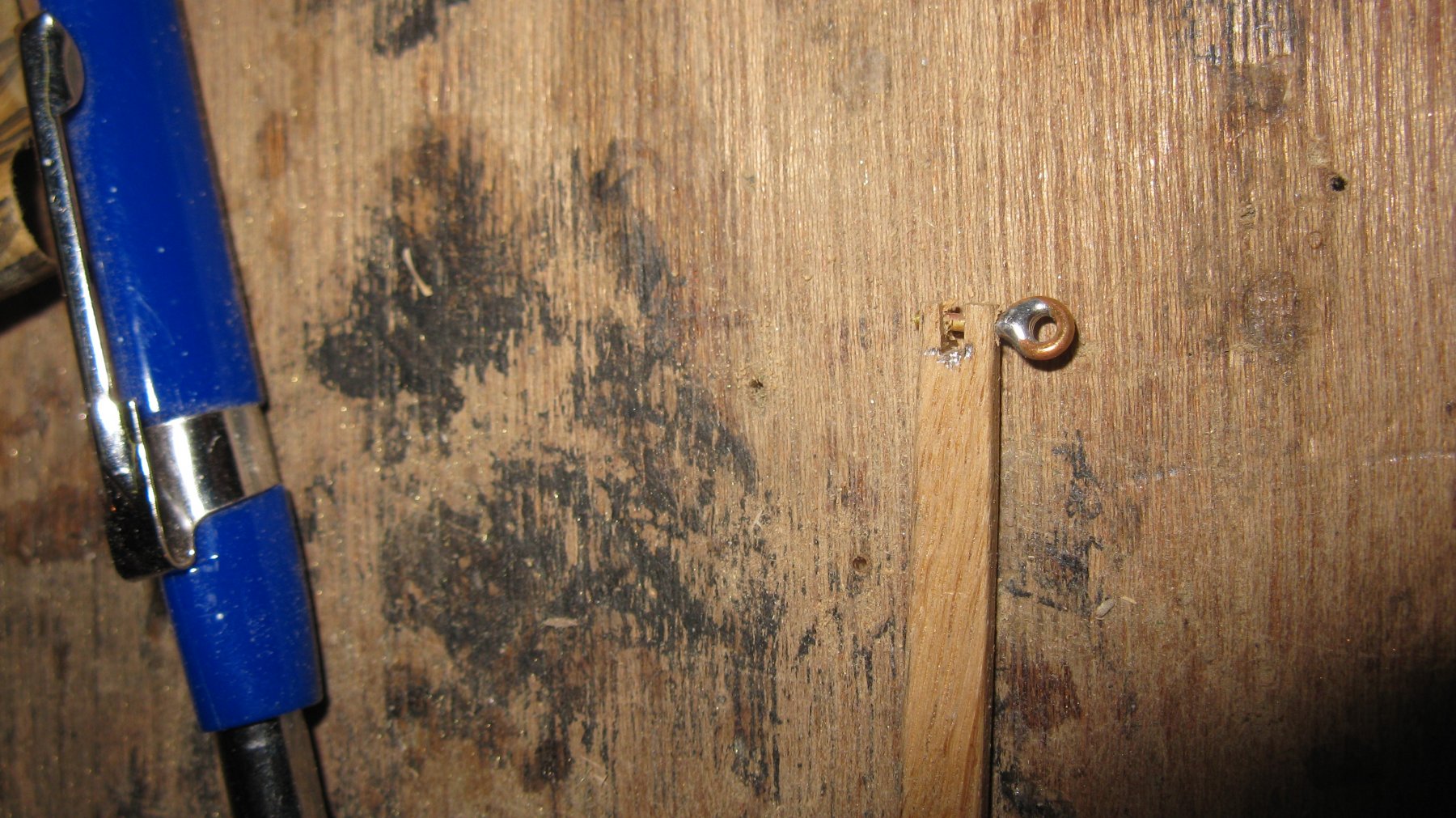
At both sides there is a slot in which the shroud will fit. The shroud is prevented from popping out by a small metal pin.

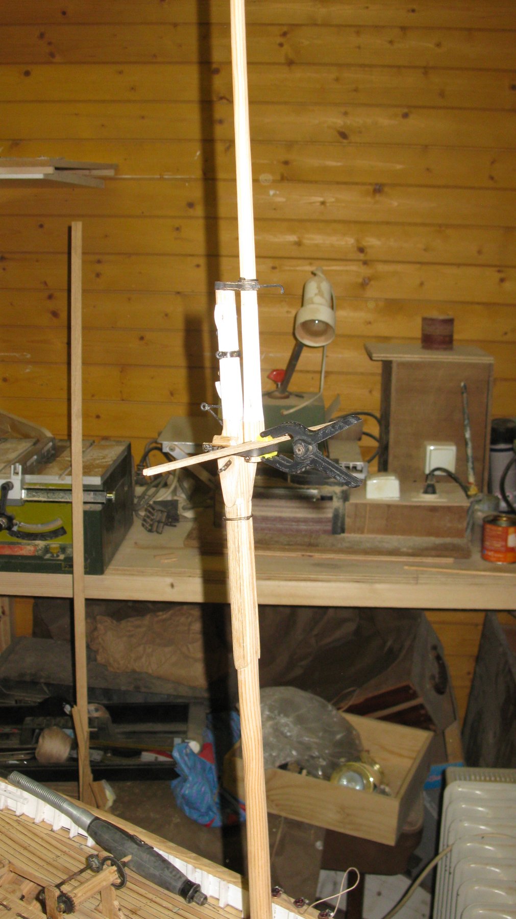
Gluing the spreader on the crosstree.
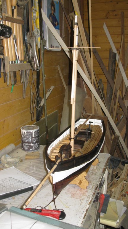
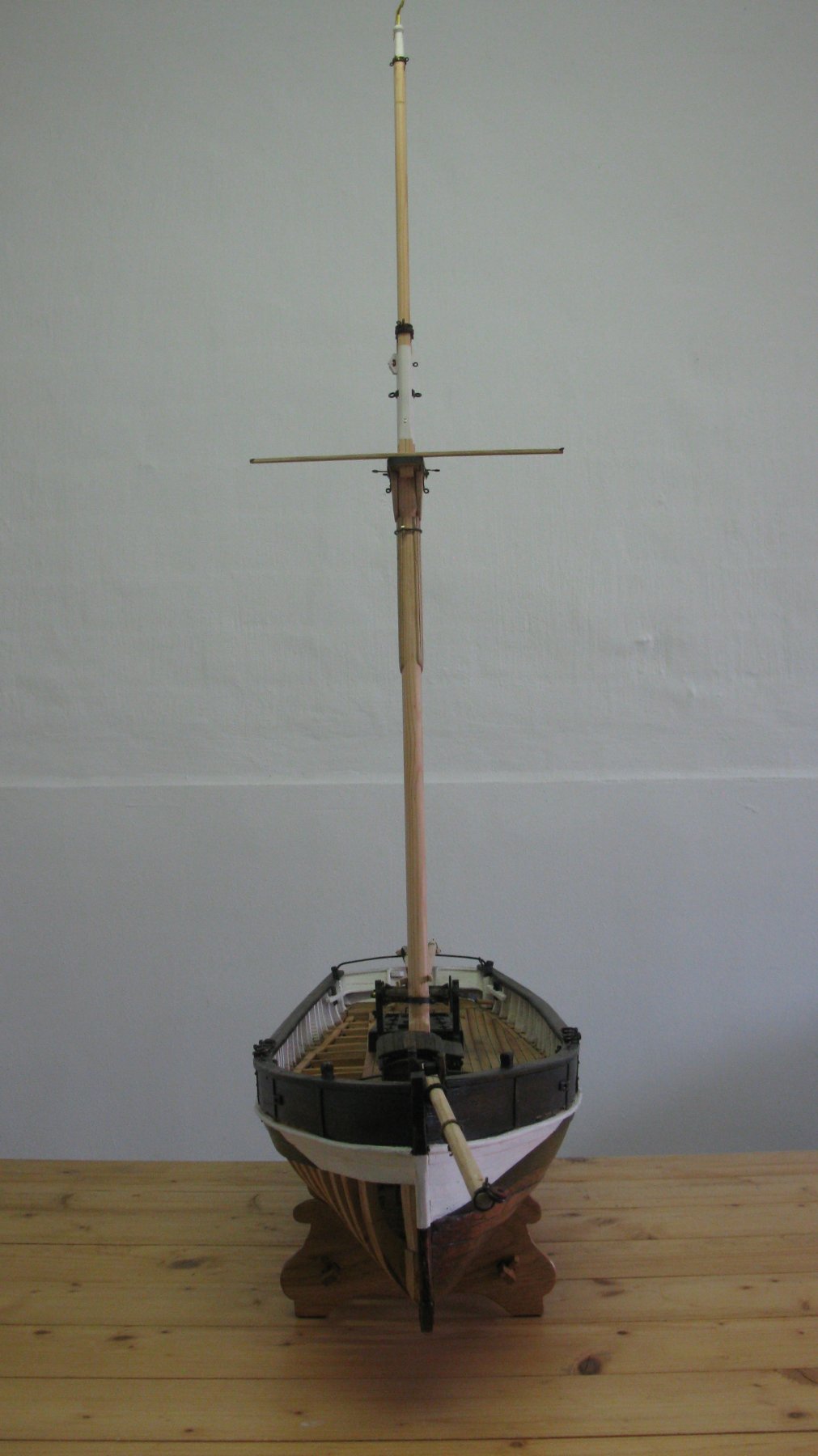
The boat with spreader and lowered top gallant.
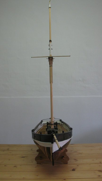
The boat with top gallant up.
-
Hello Nils and Patrick,
I learned a lof by reading all of your logs, guys. I think that still have a lot more to learn when I see all beautiful pieces which are produced on this forum. Keeping on trying to improve.
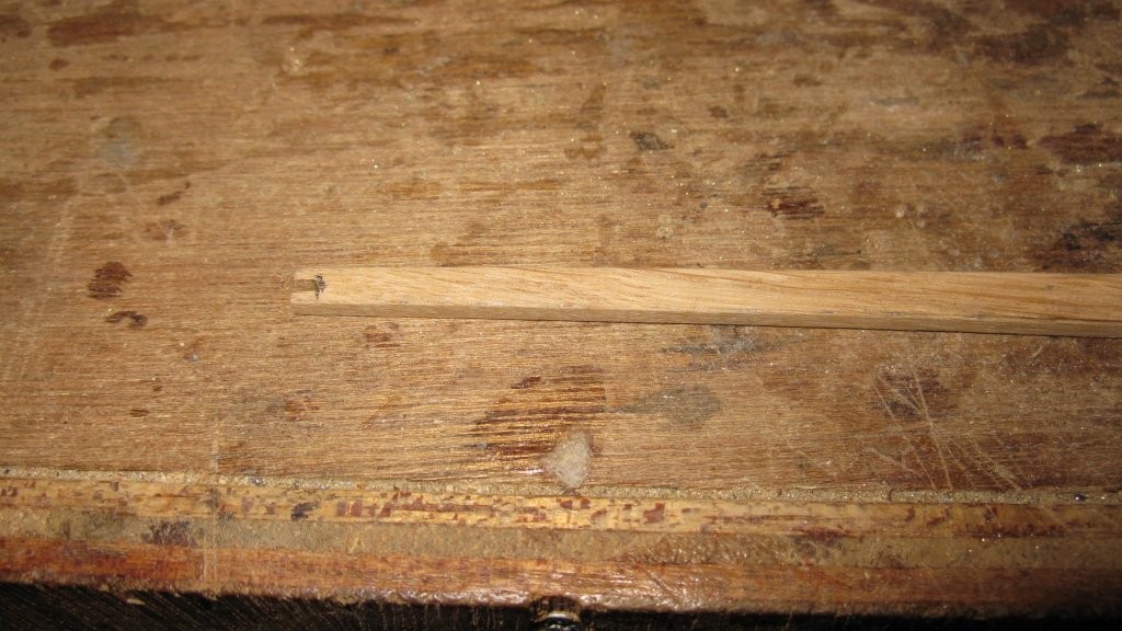
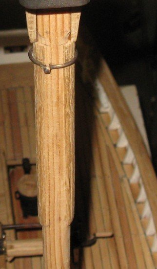
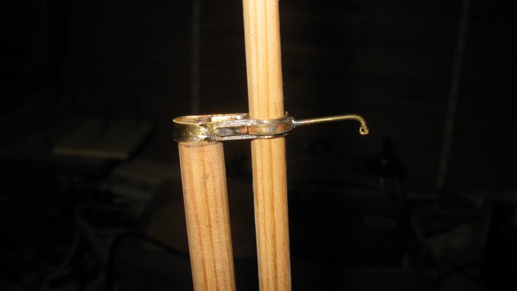
17.4 Mast. Mast laths:
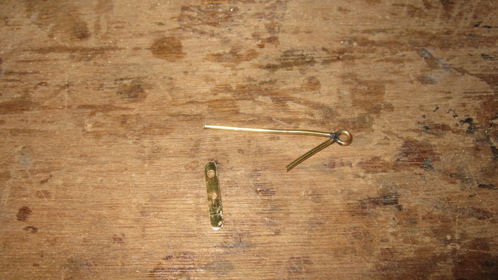
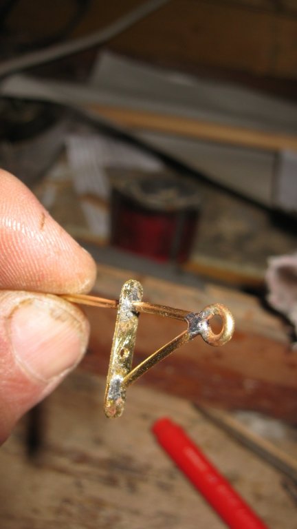
Up to 2.20m downward from the hound pieces the backside of the mast is protected against the scraping of the gaff fork by oak mast laths. The laths are glued next to each other to the mast. In the upper end I file a groove to place a metal fastening ring.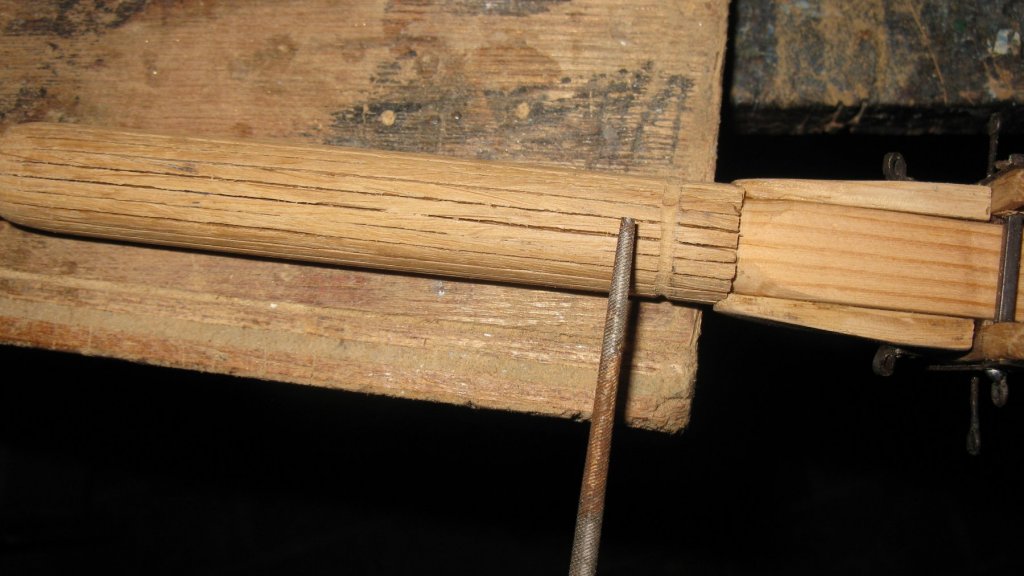
-
-
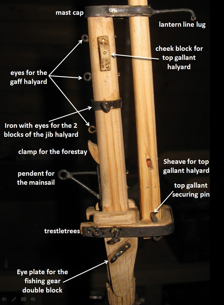
17.3 The maintop, cap and other parts
Making the cap

All the parts soldered together.


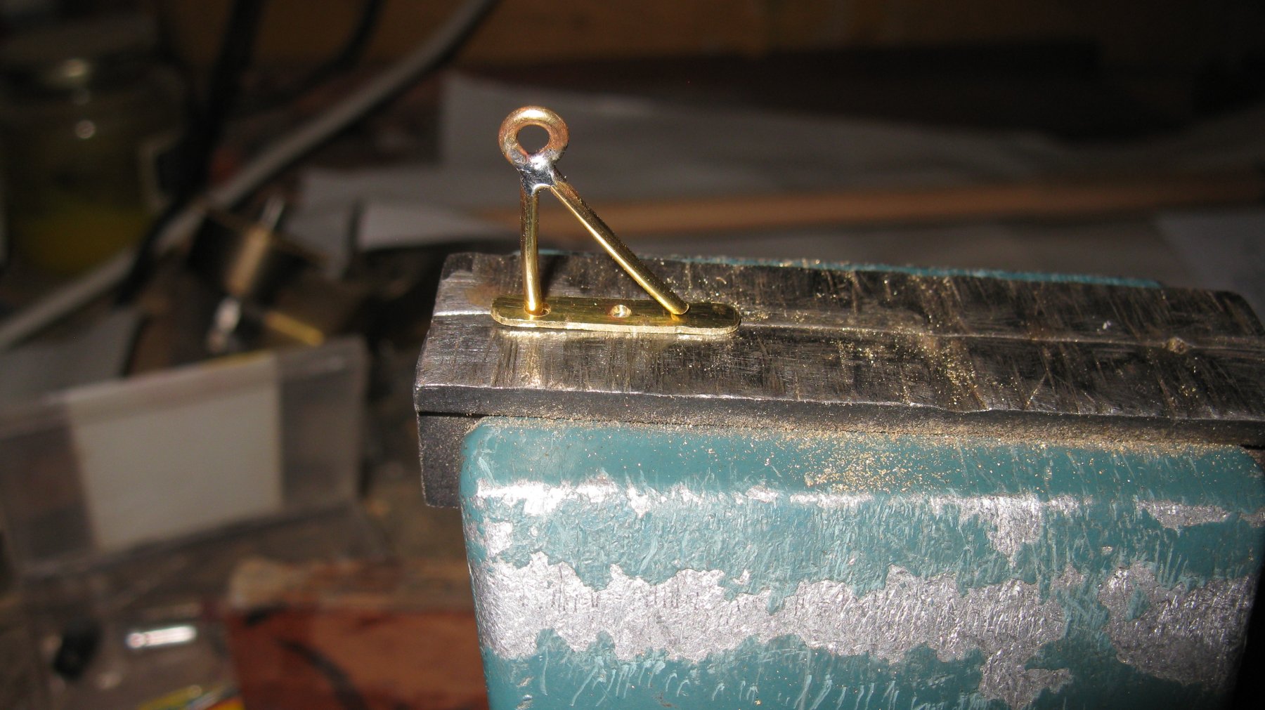
The cap on top of the mast, holding the top gallant in place. The lug with a small hole in front of the cap will keep the block for a lantern line.
Making the pendent for the mainsail.

The maintop gear.

- John Allen, Tim Curtis, Mirabell61 and 9 others
-
12
-
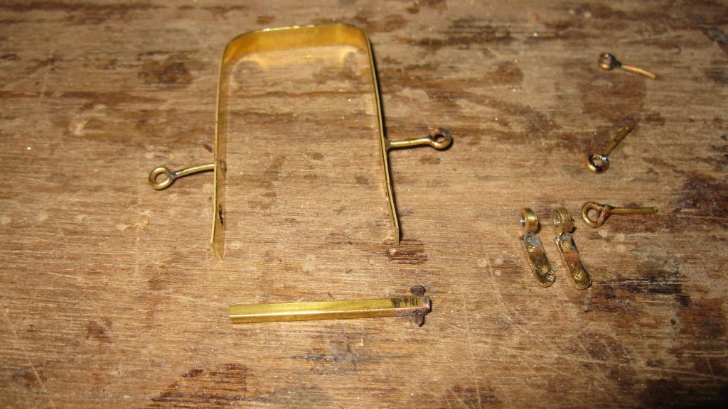
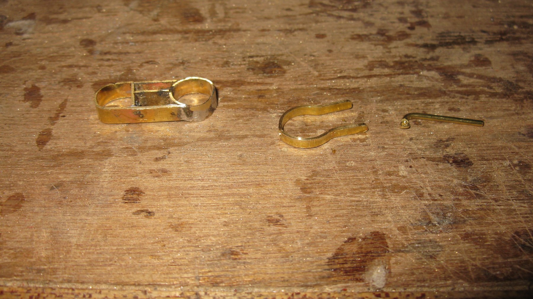
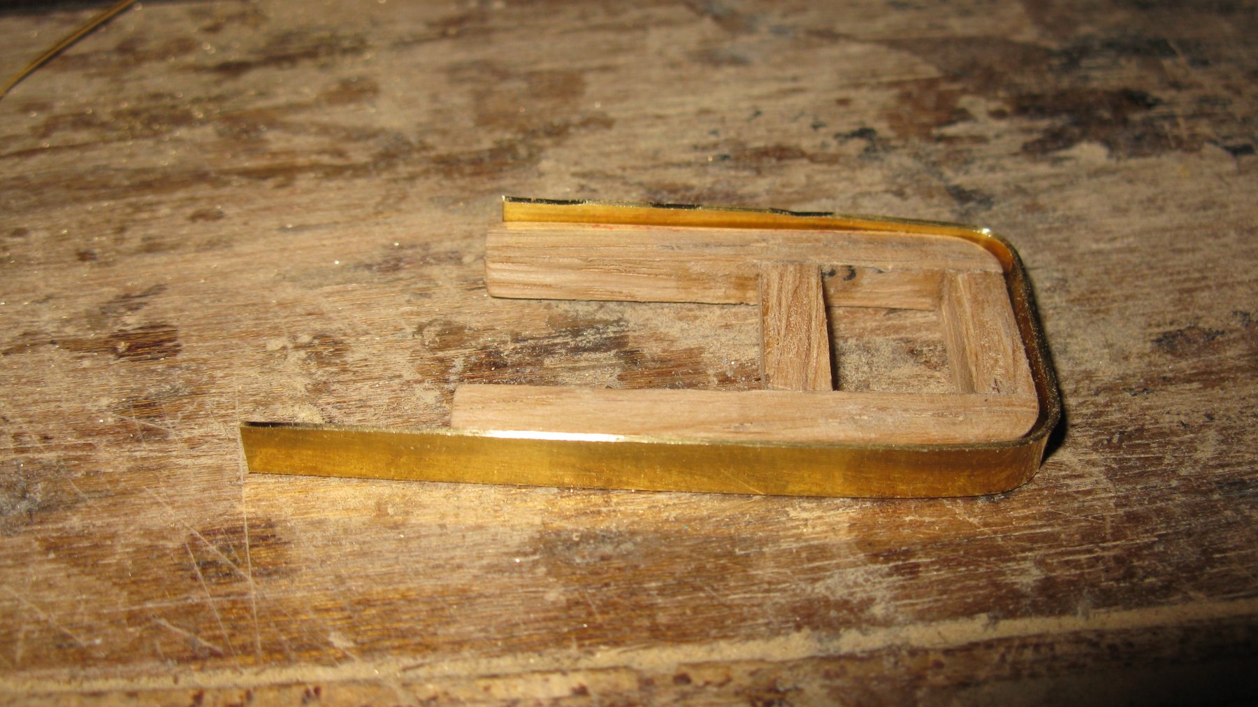
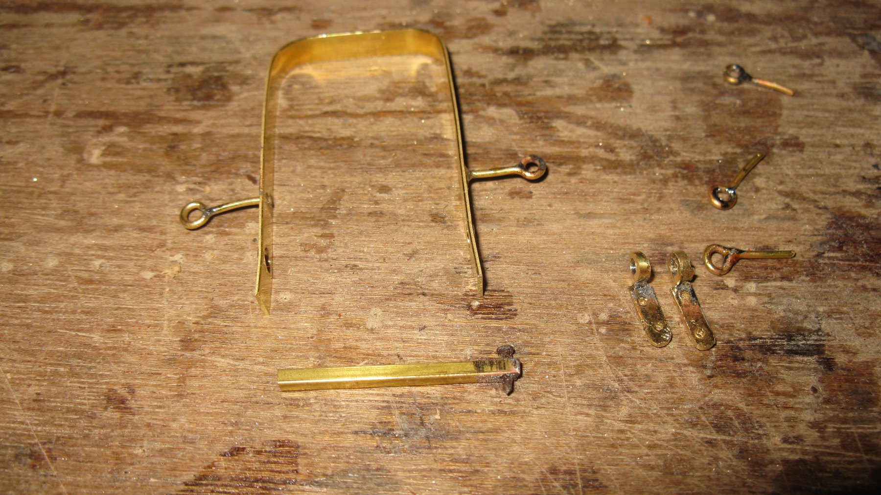
17.2 The Maintop, Trestletrees and crosstrees
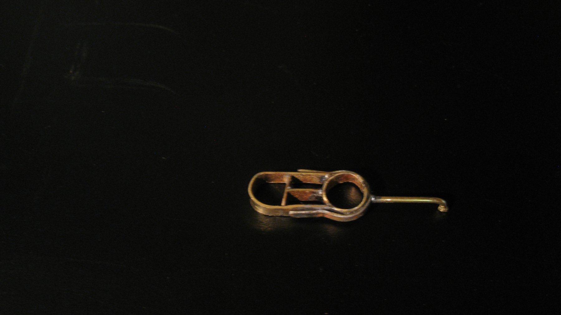
I hope I use the correct English terms for all the parts. Round the trestletrees comes a metal band.

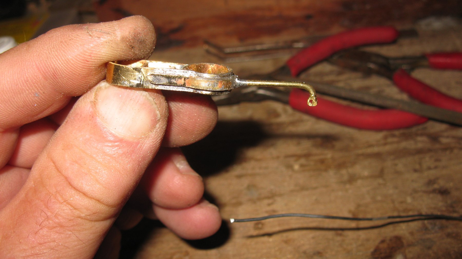
The band is equipped with a fairlead at each side. I didn't check yet what will be their use. Below lays the pin to secure the top gallant. To the right you see the eye plates for the hound pieces and 3 eyebolts which will be secured in the main top.
Gluing the protection band into its place...
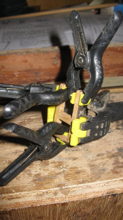

... and fixing it onto the mast.

-
Thanks Django 56 and Nils!
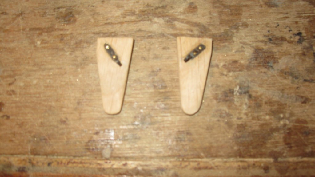
17.2 The Maintop , the hound plates
Making the hound pieces. On the piece below the paper template to saw it, is not yet removed

The hound pieces become thinner towards the underside.

Each hound piece receives a plate with an eye. At starboard side it will have a double block for the fishing gear and at port side a single block for the topping lift of the main sail boom.
- tarbrush, Captain Poison, mtaylor and 1 other
-
4
-
On 22-3-2018 at 10:09 AM, AnobiumPunctatum said:
Wow, the painting of the friese is looking great.
One suggestion: if you choose this kind of presentation, it should be good to paint the inner side wall red. this can be seen in contemporary models and also in the Marshall paintings. If it's not possible to change this detail it is also fine
Thank you for your appreciation Christian.
Thank you also to let me know the Marshal paintings. They are marvelous.
Your idea to paint the inside walls red is good, but I will not do it. With the gangways and the brackets in place it would be too difficult to do it. I used HMS Victory as an example, on the Victory The inner bulwarks are in ocher, so I believe that I am not completely wrong in my color choice.
G.L.
-
-
Thanks for your comments. Patrick, Hakan and Keith.
Part 17: Making the spars
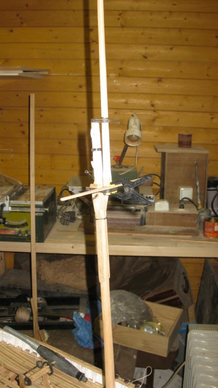
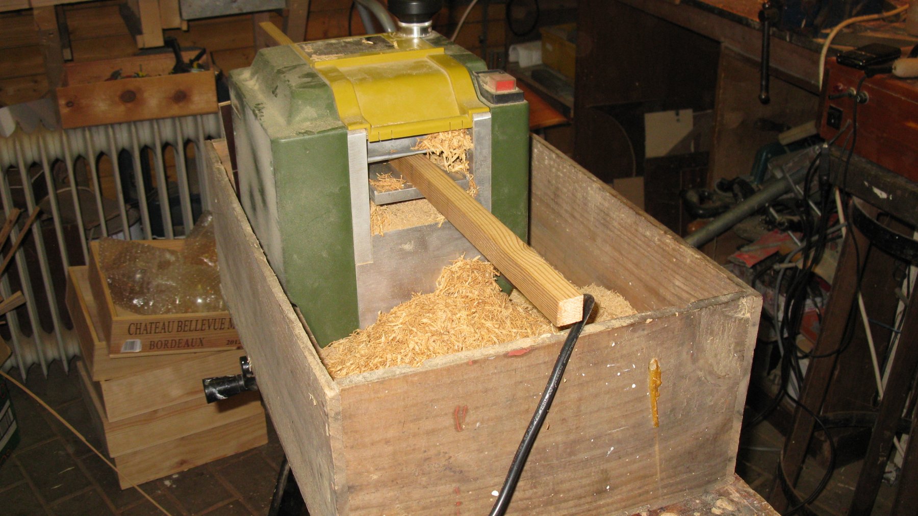
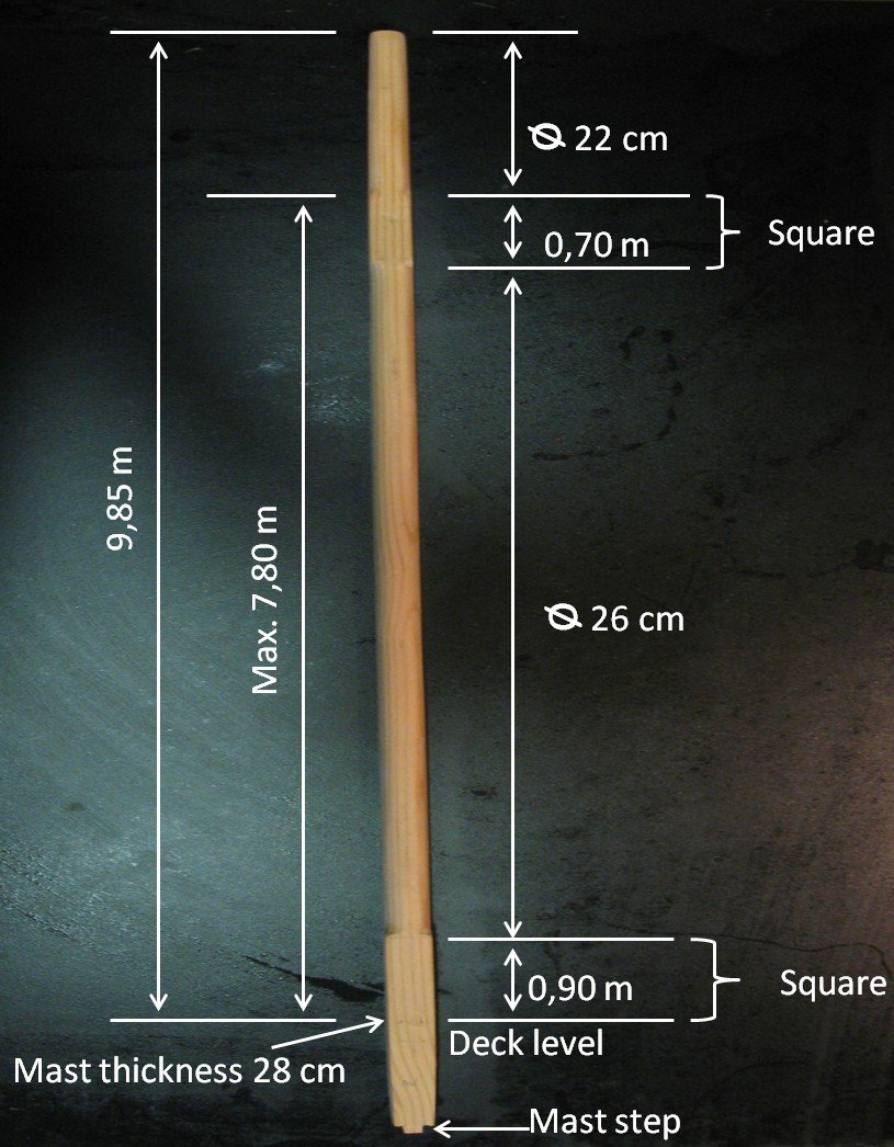
17.1 Making the mast. I make the spars from a recovered pine floor plank from the 19th century house that my daughter and her husband bought some years ago. Once sawn and planed it is beautiful pale wood with long grains
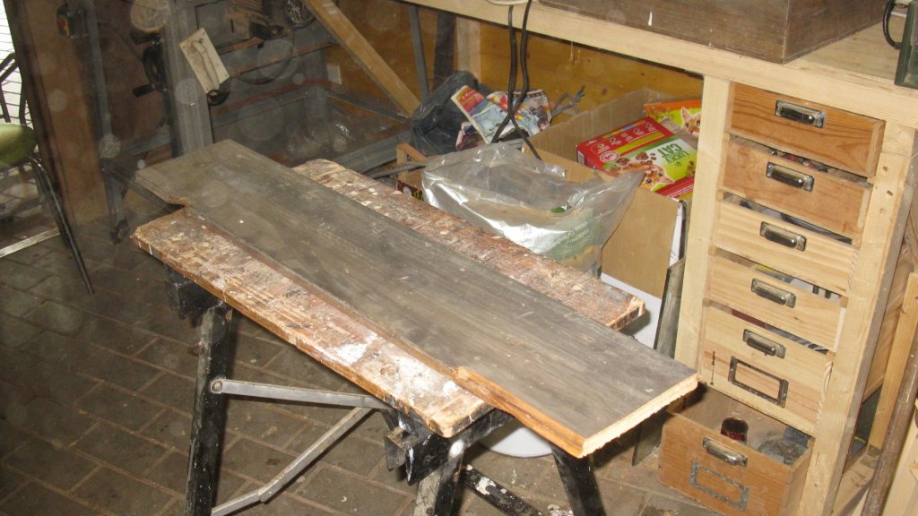
To make the spars, a description from an old revue of our modeling club (https://dedissel.weebly.com/) from the mid eighties is my guide. The description was made with help of a member modeler who was then one of the few still living fishermen from the sailing shrimper era.
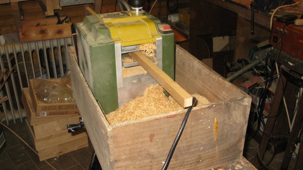
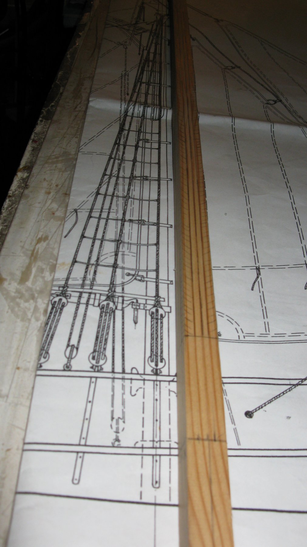
From about 90 cm above the deck height up to the top of the mast and below deck down to the mast step the mast is becoming thinner. I draw the mast width thinning with a pencil and sand the square mast to the right widths with the band sander.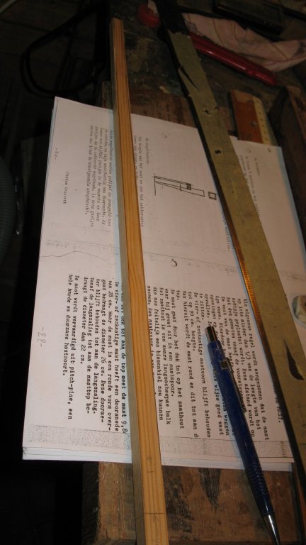

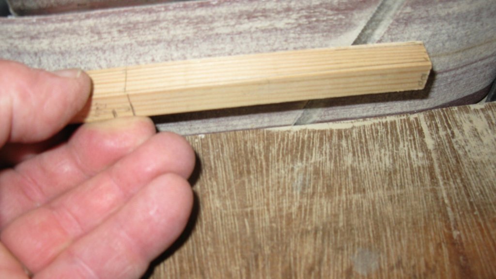
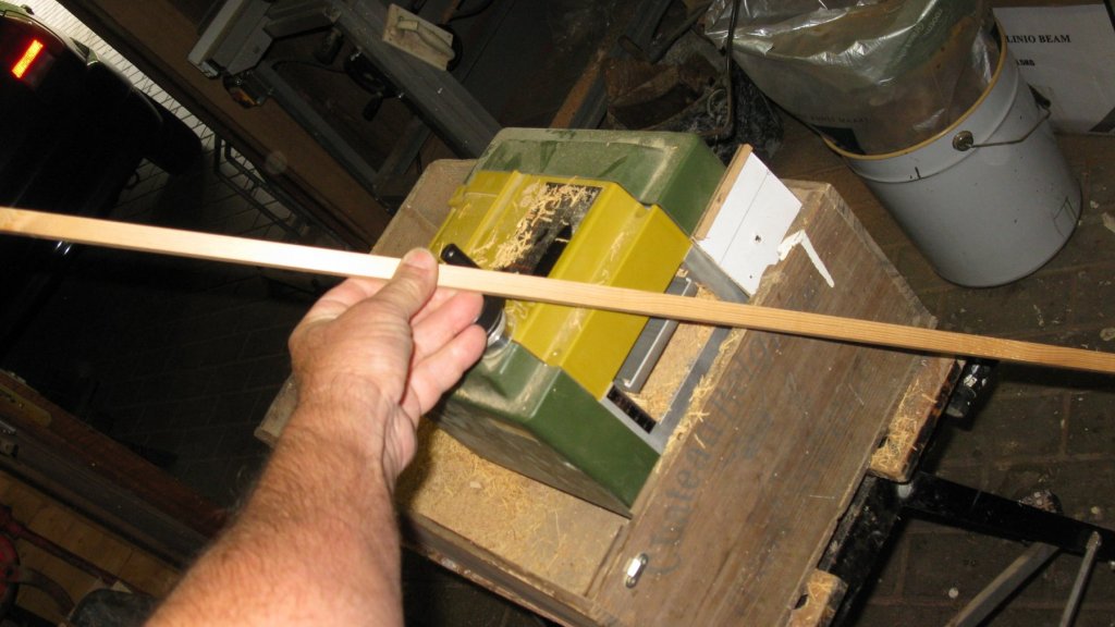
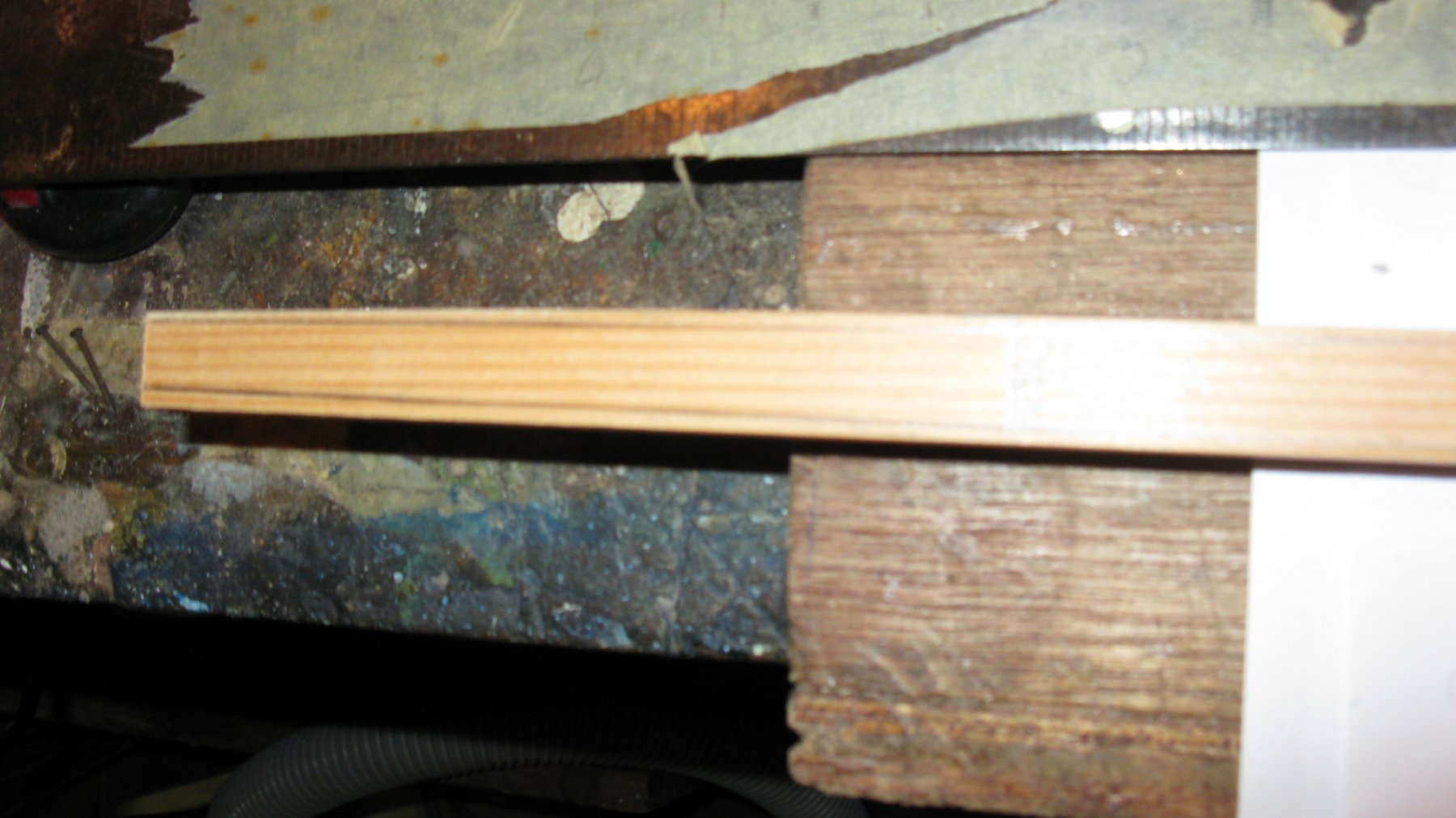
The spar now has now a more or less conical form. Now I divide each side in three with a pencil lines. Those lines help me to shave the mast in an octagon with the spoke shave.
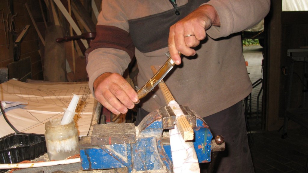

The last step is sanding the octagon round.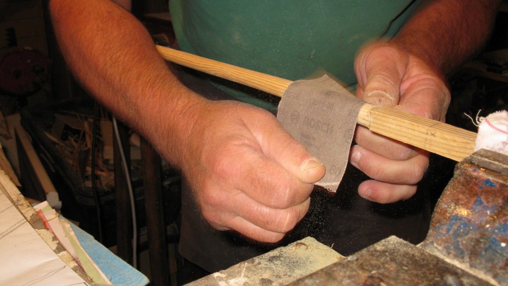
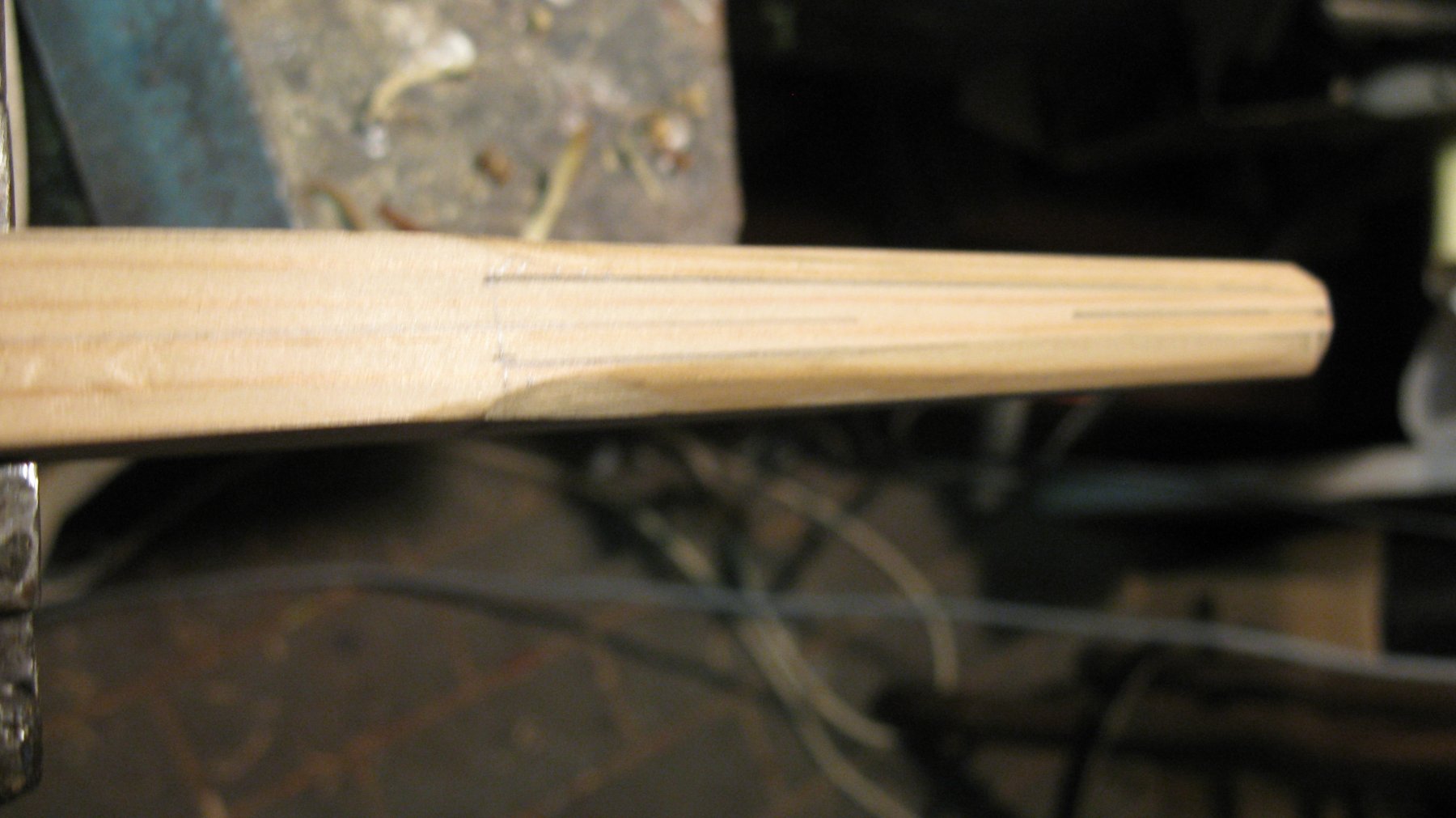
The mast is square on two places: at the height of the hound pieces and at the height of the deck to 90 cm above.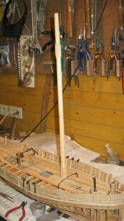
Shaping the transition between round and square with the Dremel.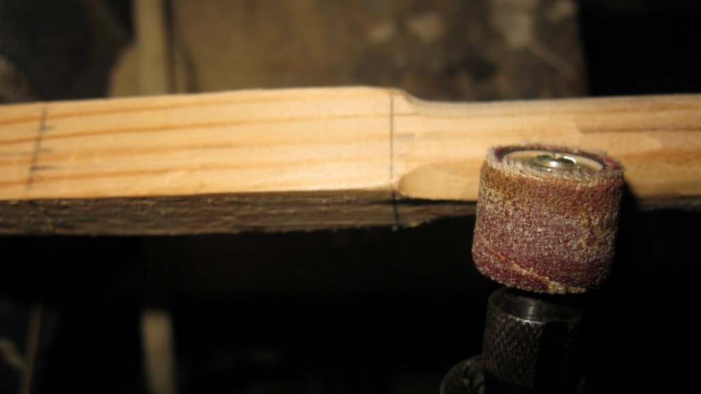
The scale 1/1 dimensions of the mast.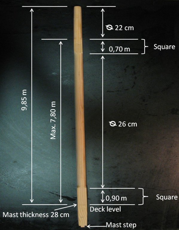
- DORIS, paulsutcliffe, mtaylor and 8 others
-
11
-
-
-
-
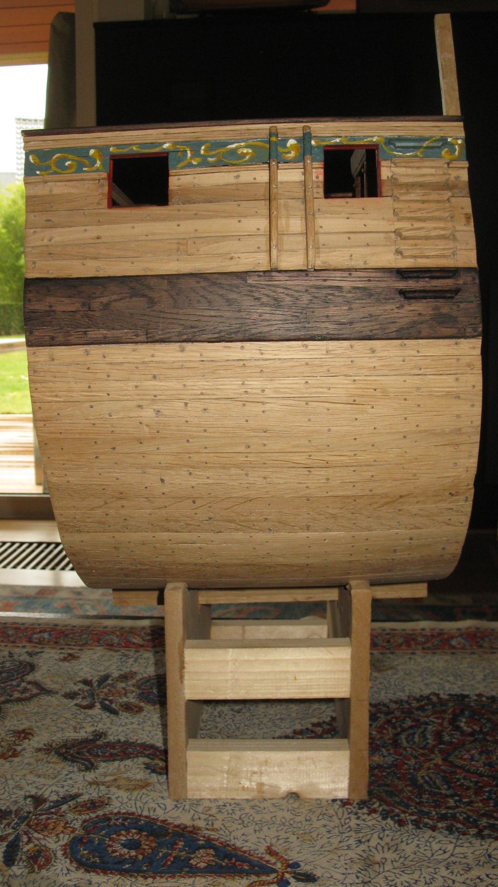
Shadow and white spots added

-
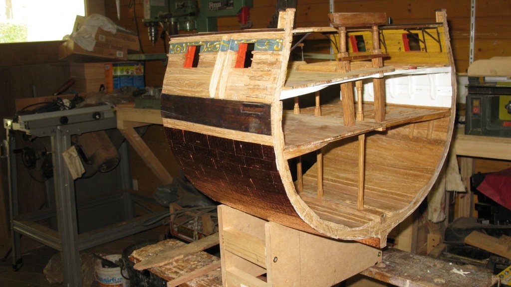
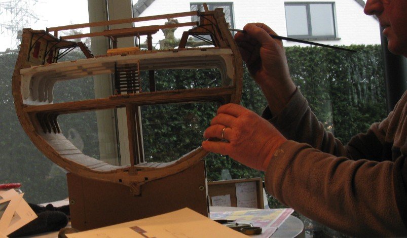
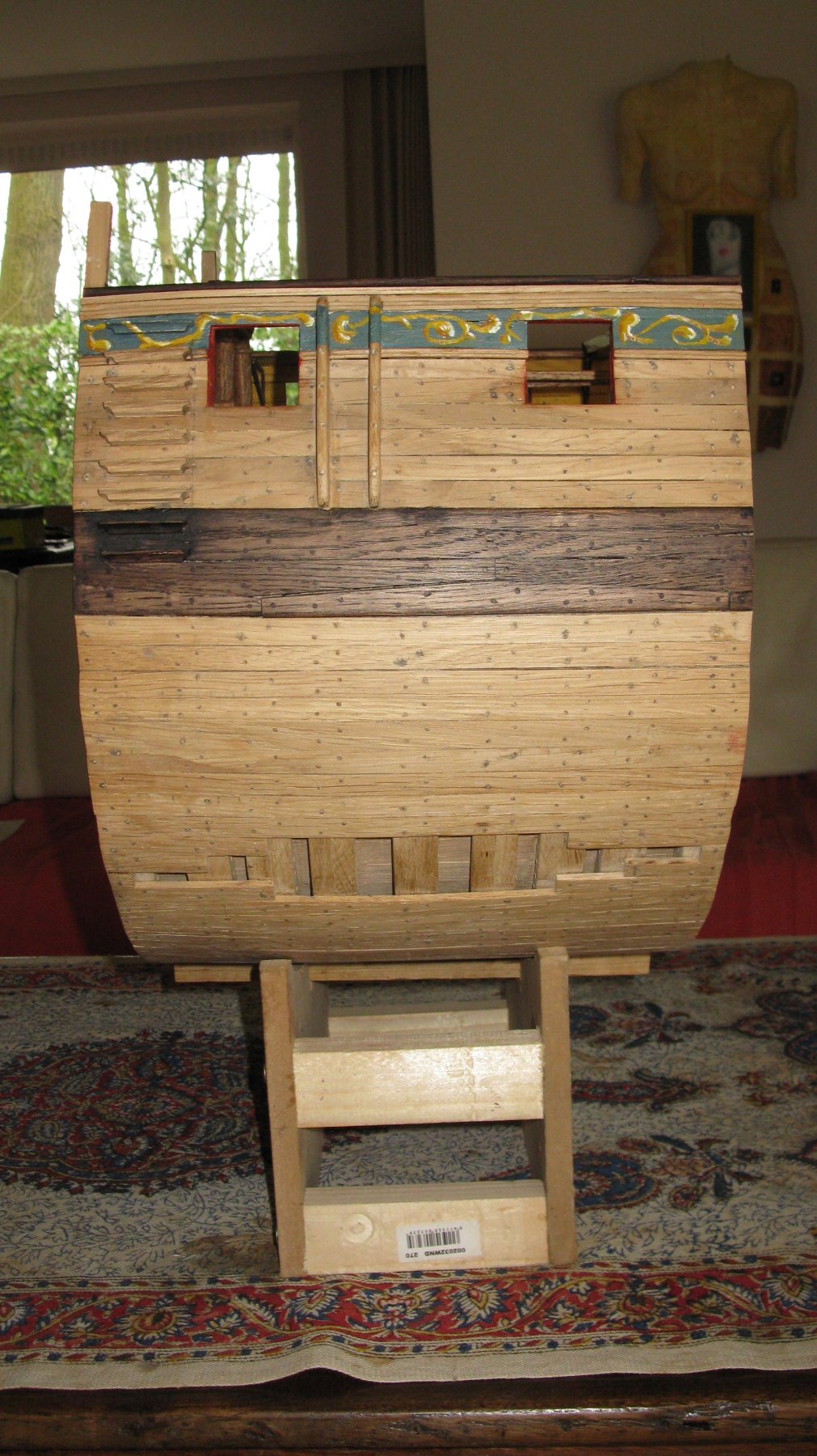
Now comes the most difficult part, the decorations. I am not an experienced painter. Painting the molding on a flat paper is not so difficult, but reproducing it on the model which has obstacles as fenders and ladder steps is a whole other story. With blood, sweat and tears and of course with yellow paint I can produce something that looks a bit like ornamental garlands. It still has to be finished with white light spots and darker yellow shadows.
On the second picture you can see that the gaps between the planks were not yet filled when I was painting the moldings.


Oostends schipje by G.L. - scale 1:20 - Ostend shrimper - first POF - Edition 2
in - Build logs for subjects built 1851 - 1900
Posted
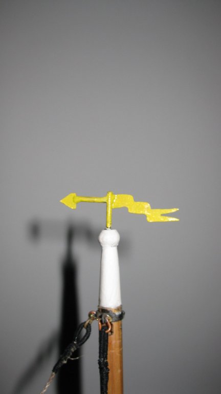
17.6. Mast. Weather vane.
On top of the top gallant comes a weather vane.
I paint it in yellow.