Chuck
-
Posts
9,703 -
Joined
-
Last visited
Content Type
Profiles
Forums
Gallery
Events
Everything posted by Chuck
-
 More pics? You should be getting so close close now. I think you will miss working on it.
 -
HMCSS Victoria 1855 by BANYAN - 1:72
Chuck replied to BANYAN's topic in - Build logs for subjects built 1851 - 1900
So how goes the research on the rigging details. Getting close to resuming work on her. Hope to see more of the model soon Pat.- 1,013 replies
-
- 2
-

-
- gun dispatch vessel
- victoria
- (and 2 more)
-
Oh almost forgot to mention......once you start making those port lid hinges you will be grateful there werent lids for every port!!! 😀
- 1,784 replies
-
- 8
-
-
- winchelsea
- Syren Ship Model Company
- (and 1 more)
-
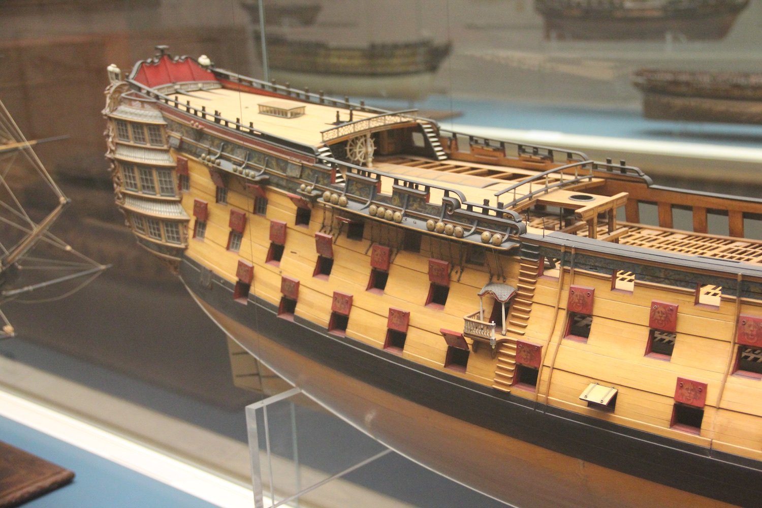
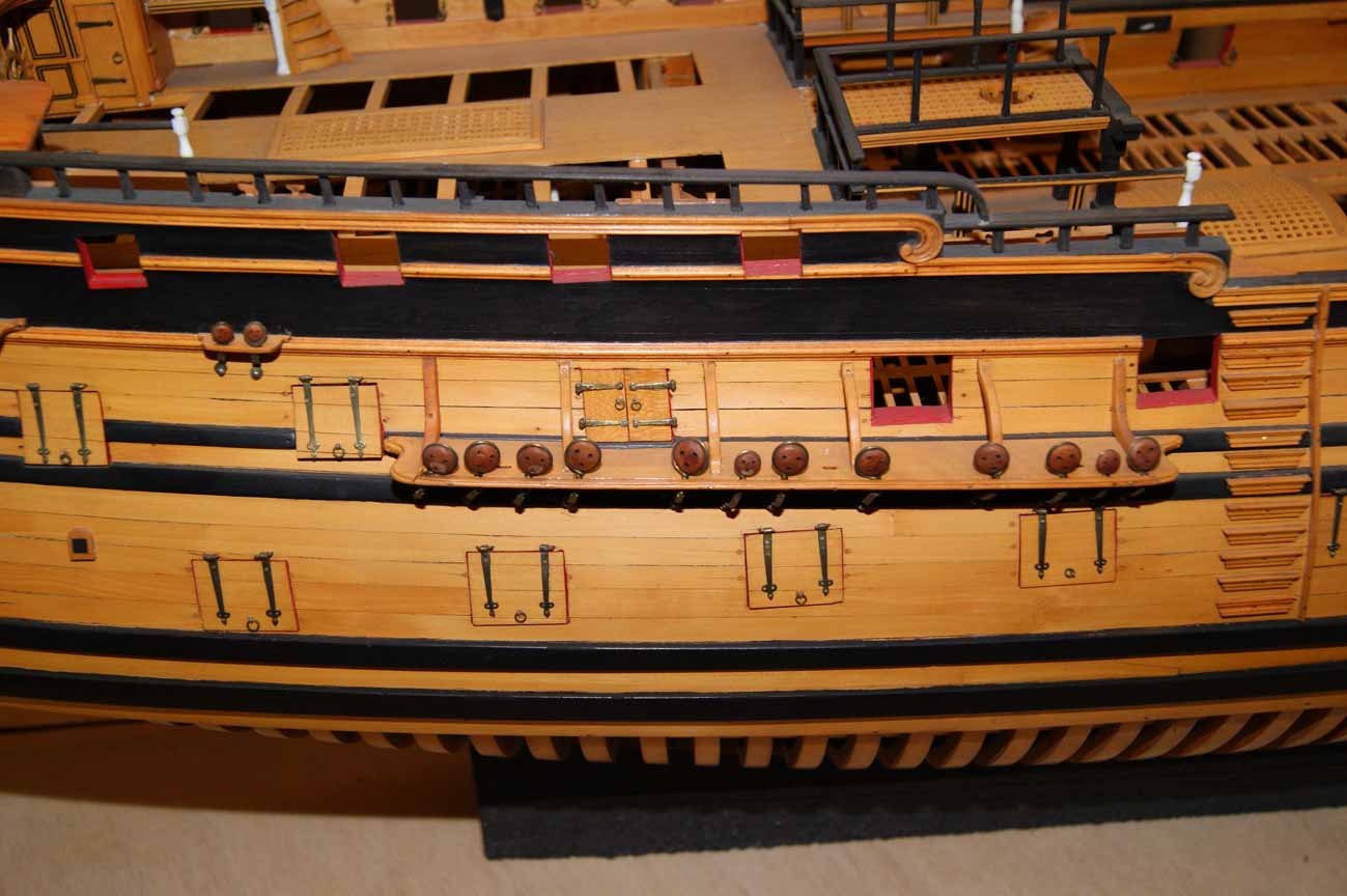
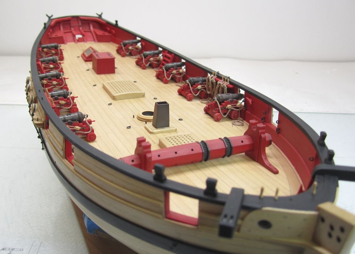
Thats the way they did it on these frigates. In reality they only had a few on the gun deck. Never did they have port lids along the waist on the weather decks or for all the ports. What would be the point. Just a few of them aft and one or two at the bow. Although there are rare exceptions. Just look at all of those photos of the contemporary models I posted....include those for other frigates and larger rates in our gallery. The gun deck always had the port lids omitted mid ship. Although some larger ships had a few more than just four aft because they were longer. For 32's they mostly had about four lids aft and just the one or maybe two forward including the bridal port . With all of the others left open. For Winnie specifically.....its just the five. Here is yet another prime example. In this case two ports up front.....and three aft. A slightly older example in the 1750's. But a shorter smaller 32. Chuck
- 1,784 replies
-
- 6
-
-
- winchelsea
- Syren Ship Model Company
- (and 1 more)
-
Nicely done!!
-
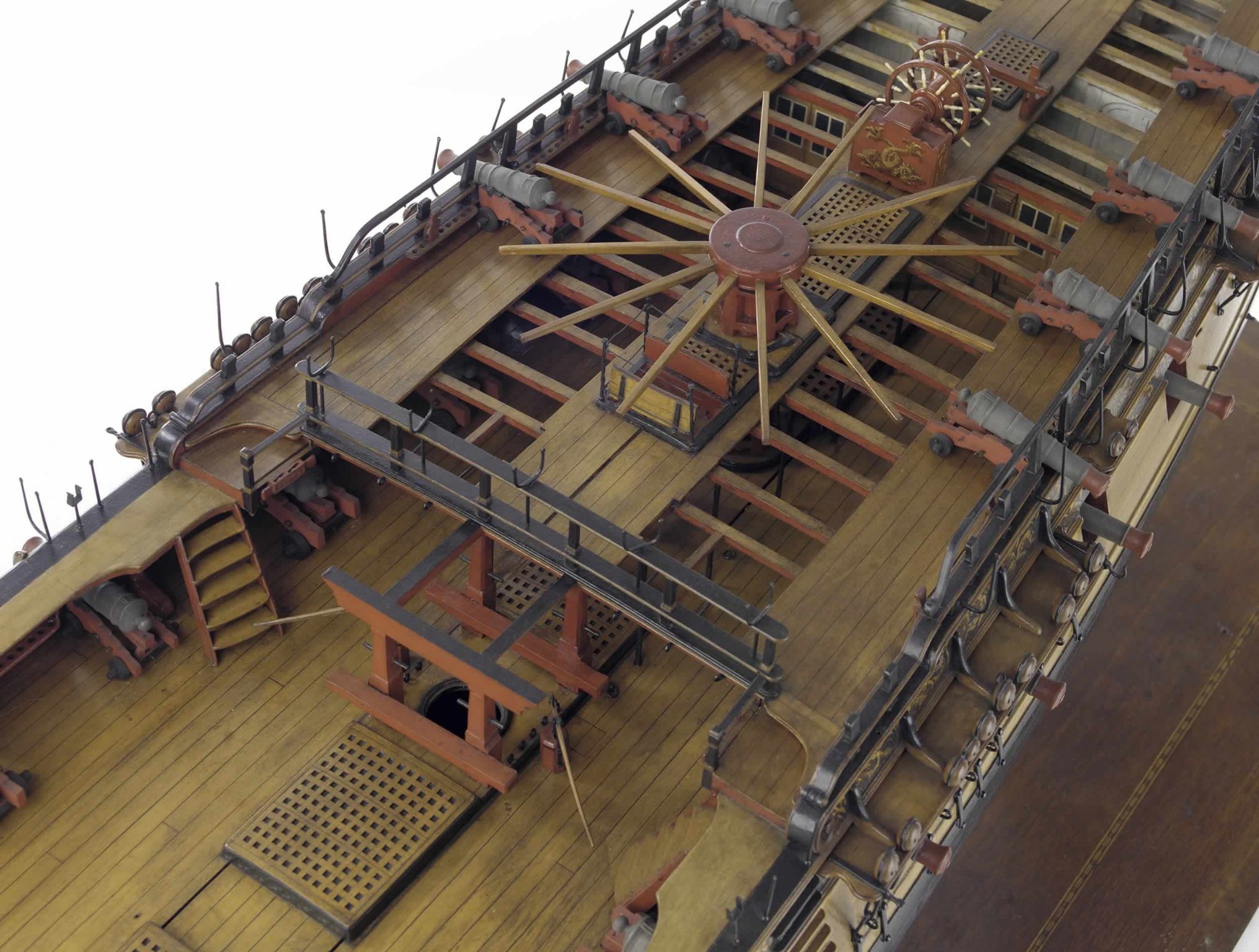
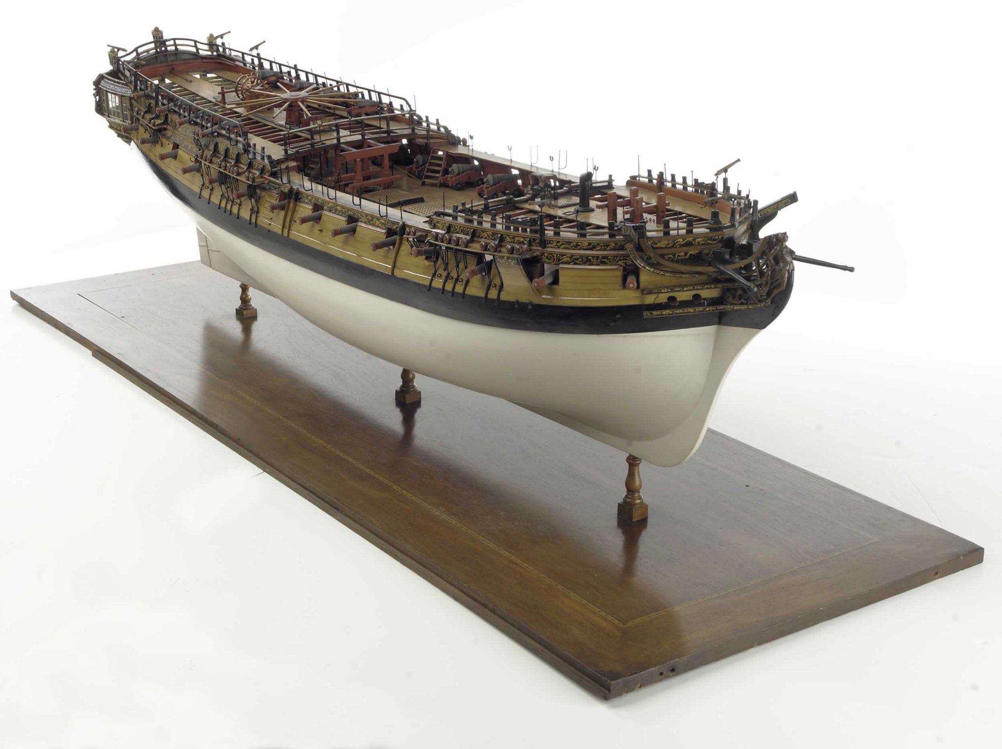
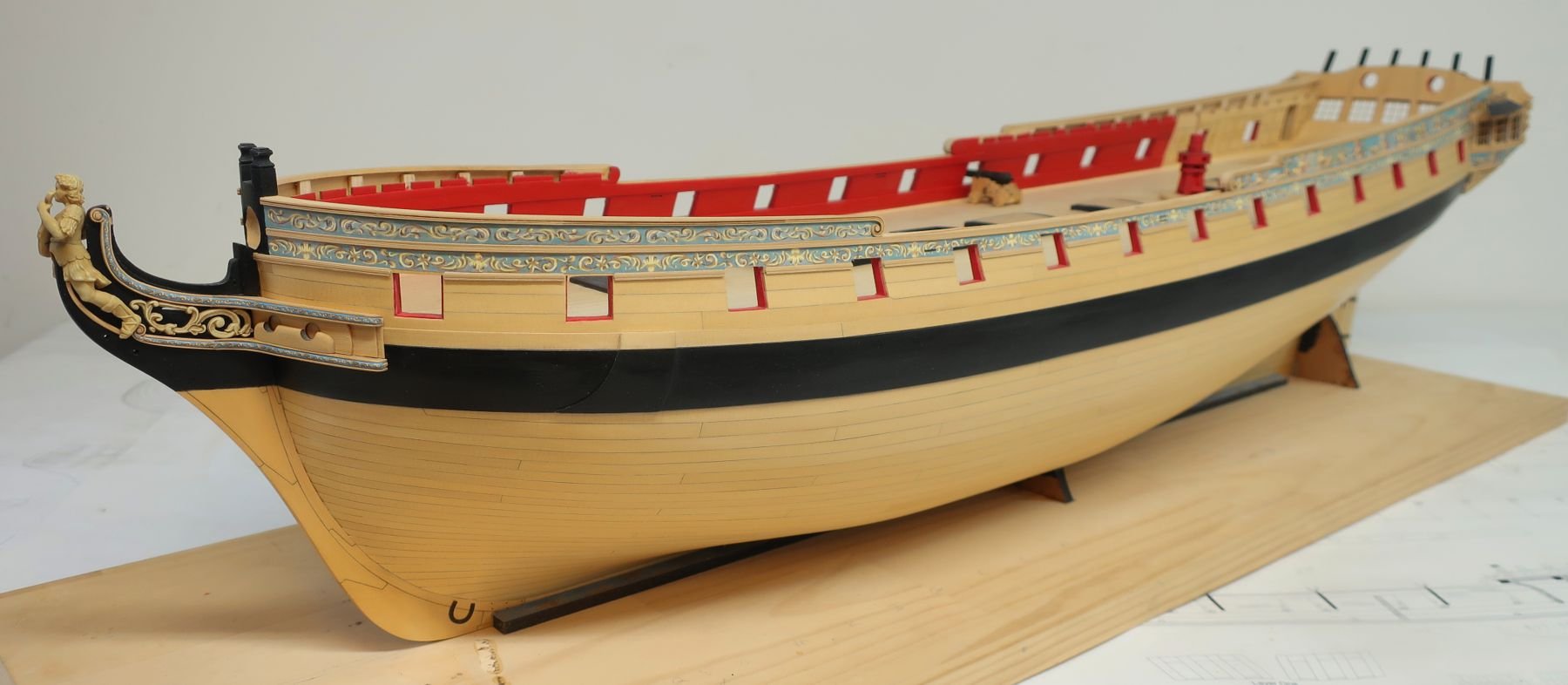
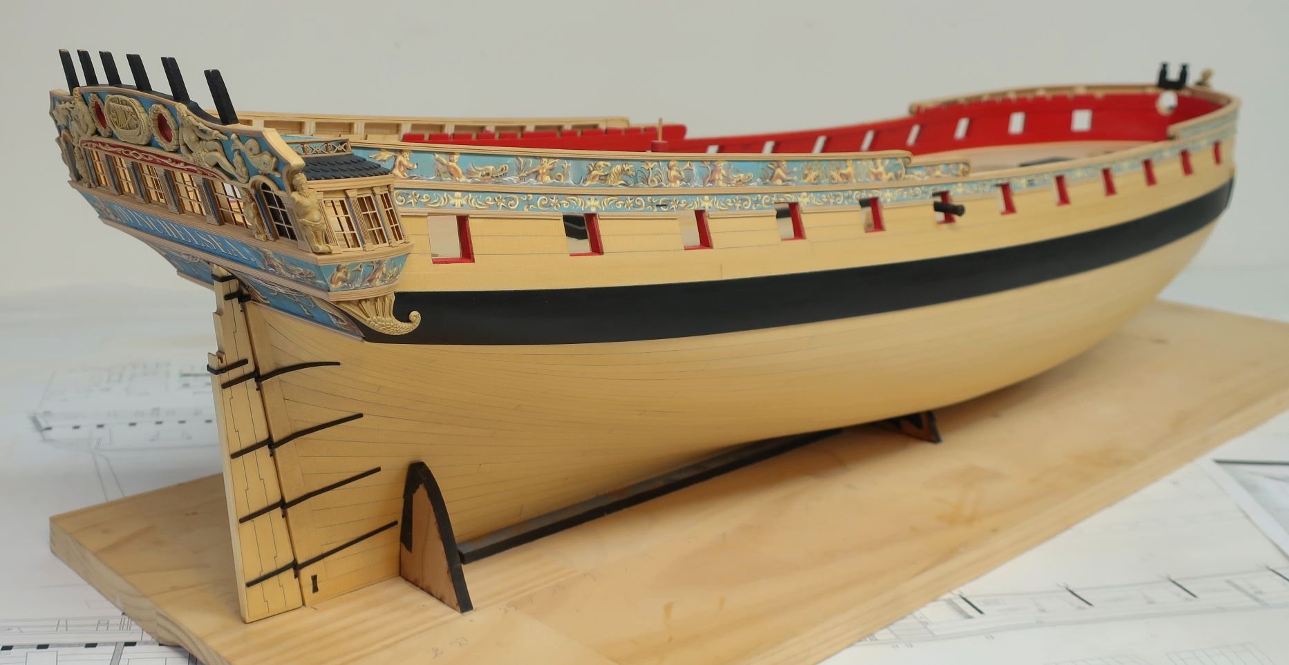
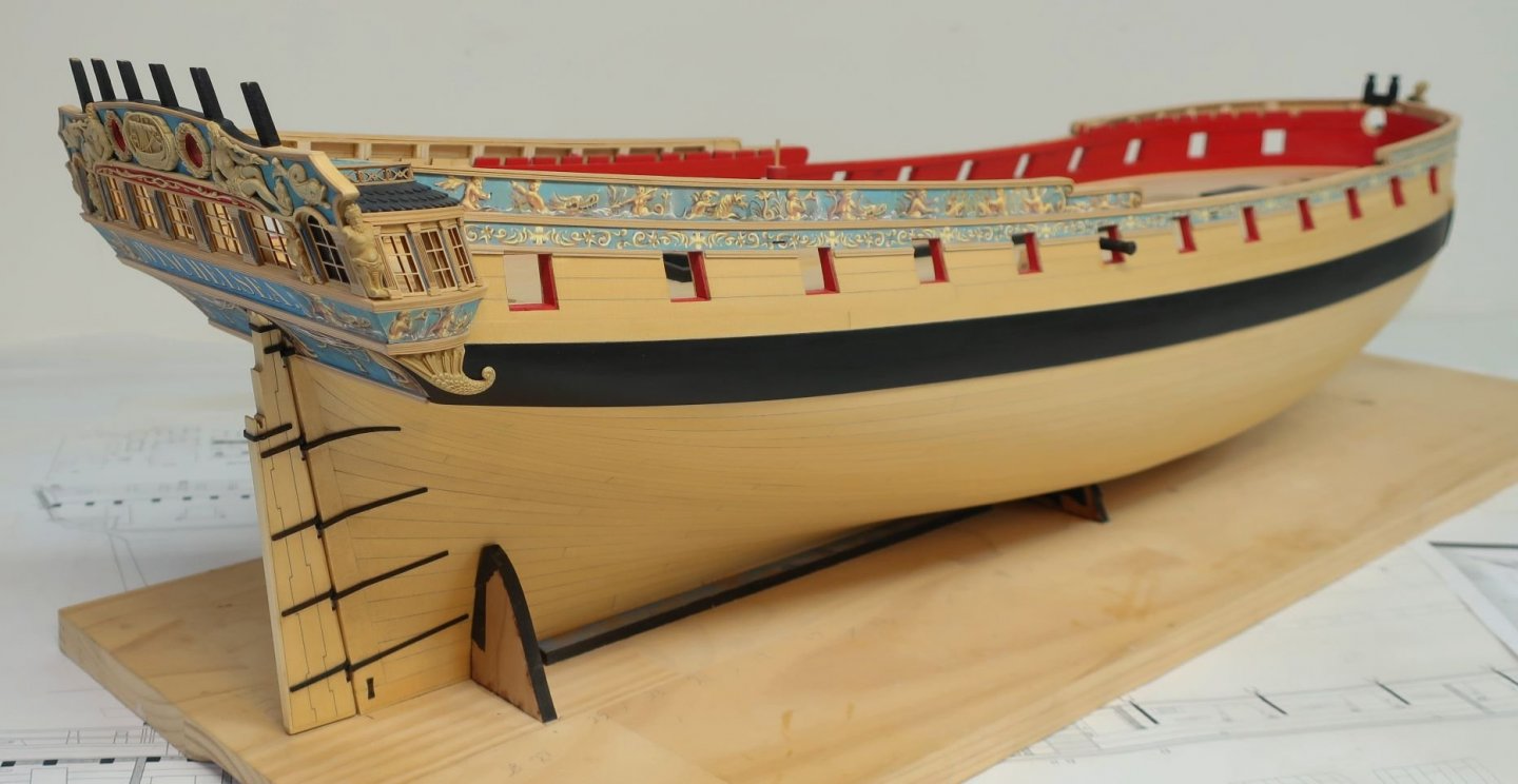
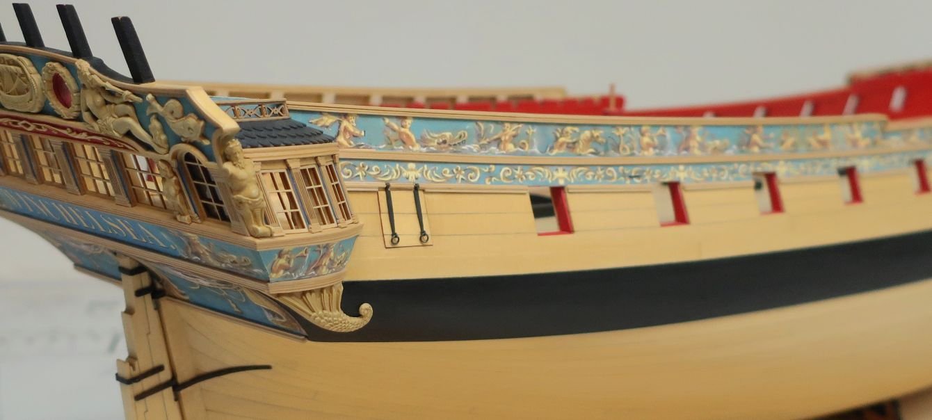
You do have to look extra hard for contemporary hull models that show guns. But they are out there. Here is my favorite. Its Amazon....not one instance of rope on this model. Again this isnt meant to discourage any of you guys from adding those details but I do want to explain why I am doing what I am with my model. Its really my best attempt at a homage to the old time builders. It was a widely accepted practice to not show a lick of rope unless the model was fully masted and rigged. Not even on the bumpkins shown at the bow or hammock cranes or ship's wheel.


- 1,784 replies
-
- 20
-
-
- winchelsea
- Syren Ship Model Company
- (and 1 more)
-
Its really hard for me to tell with certainty. Best to wait for the parts to arrive and do a comparison to see if the printout is correct. Chuck.
-
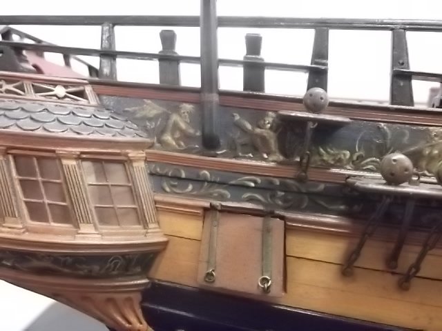
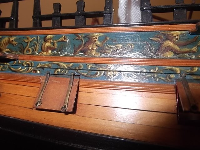
You can do that of course but they will stay open without them. Another interesting discussion is the fact that many or even most contemporary models that are not fully rigged, are completely without any rigging at all. Not a single rope of any kind on any of them. Most dont even show the cannon not to mention that the guns are rarely rigged. But in present times, builders have a kitchen sink approach which is fine and I fully expect most to show fully rigged cannon...ships wheel...and even port lids. Having said that, I will not be showing the lids rigged. Its too much for my tastes. I am still on the fence with regard to rigging the cannon etc. I will post a few pictures that will show contemporary practice. Its also good to leave some small details up to each builder so they can make their own models more unique...so builders choice! But I am still on the fence if I want to follow the common contemporary practice......to me it just looks so nice and less cluttered. Although I will at least fully rig one cannon to show folks how its done and then if I decide otherwise....remove it all. I know it seems crazy. But as many of you are aware, for me....my Winnie model will be my best attempt to build a POB version "or homage" to the most beautiful Contemporary hull models. With the end goal being if set side by side any of them my model might hold up beside some of them shown below. The first examples are of Winnie.

- 1,784 replies
-
- 16
-
-

-
- winchelsea
- Syren Ship Model Company
- (and 1 more)
-
Thats gonna be a while. I want to concentrate on getting Chapter 5 out first. Chapter 5 will be a shorter chapter so it shouldnt be too bad... Next, It will include finishing the port lids, adding the bulwark details, the cheeks at the bow, the stairs, possibly getting all the deck beams made and temporarily positioned. Then of course all the cannon on the gundeck. I remember what was involved when I made the guns for Cheerful......There are so many more on the Winnie (24 on the gundeck). Thats gonna take a while. There will be so many carriages to build, LOL. So I will prob offer them as a stand alone so as to not hold up getting Chapter 5 parts ready for delivery. Having flashbacks to when I did them on Cheerful. Chuck
- 1,784 replies
-
- 17
-
-
-
- winchelsea
- Syren Ship Model Company
- (and 1 more)
-
Everything is looking really good Ryland. Almost there!!!!
- 263 replies
-
- 4
-
-

-
- Medway Longboat
- Syren Ship Model Company
- (and 1 more)
-
Thank you Bruce... I must say its nice to work on the model with regularity now. I forgot what that feels like.
- 1,784 replies
-
- 5
-
-
- winchelsea
- Syren Ship Model Company
- (and 1 more)
-
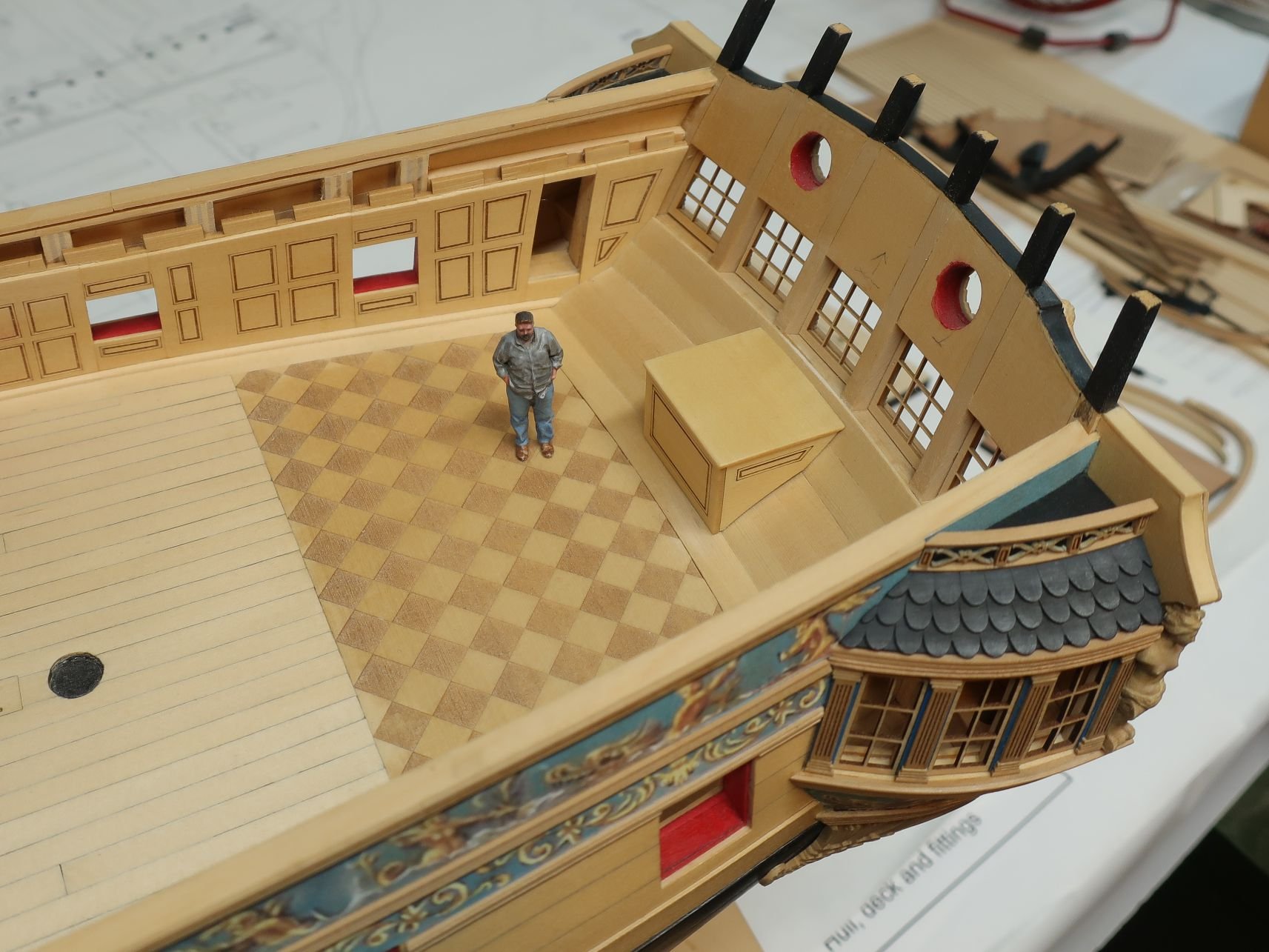
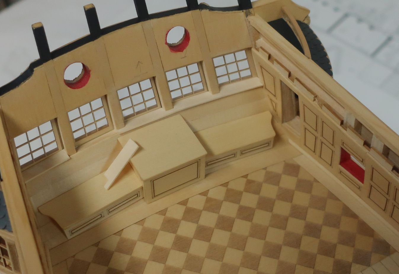
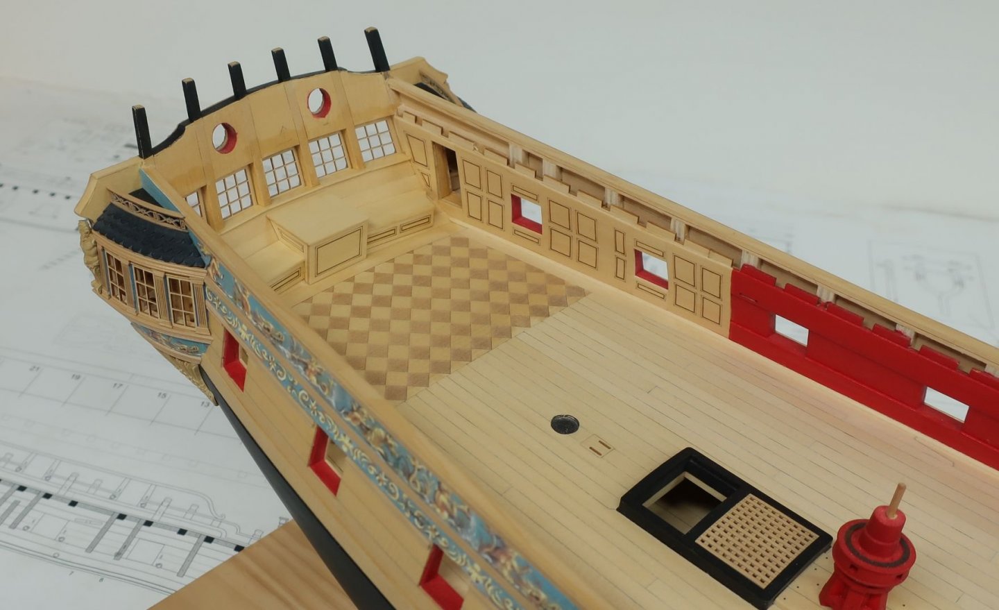
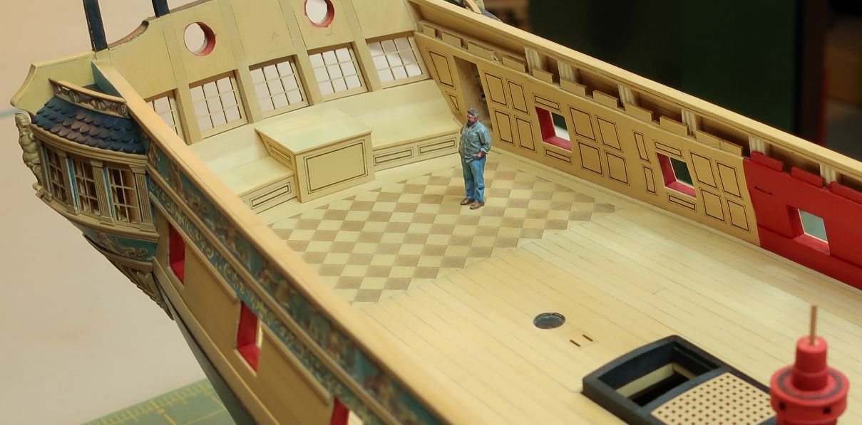
With the benches all done, its finally time to permanently glue those stern windows in position. This includes the acetate for the simulated glass. Just a tiny drop of glue was used to glue the wooden window frames in permanently. Then the acetate... For these as you might know, you cant use CA glue. It will fog up the acetate awful and look pretty bad. You want to use as little glue as possible or even no glue at all. We will be positioning window sills inboard to finish off the look. They will also hold your acetate in position. With the acetate in position I proceeded to cut lengths of 1/4" x 1/32" strips to fit between each window as a sill. This is tricky slow work but well worth the effort. It gives the whole stern bench area a clean look. You will cut these to shape just like we did for the transom cap. Just notch them out and leave a slight over hang. You can see my final piece yet to be positioned below. To complete this area sand the forward edge after all of these pieces are glued in place to even out the overhang. Then apply some wipe on poly. I am quite happy with the results even though most of this detail will be hard to see at all once the quarter deck is framed and planked. I also thought I would mention that the way I like to work is from the stern forward with all the deck details etc. Next I will start adding the ringbolts, cleats and other features to the bulwarks and get the cannon in position. But first there is something else that can be done and you guys dont even have to wait until chapter 5 comes out. You should be able to gather up all the materials you need. I am referring to the gun port lids. You will need five per side. There are many ways to make these of course. In this case I will be using brass strips blackened. But its easy metalwork. No soldering!!! I made one port lid today just to go through the process. I will detail how I am going to make these so you guys who are waiting, can do these ahead of receiving Chapter 5. They are working port lids. I will show the aft lid closed on my finished model but you guys can do otherwise. I will keep them all closed while I am working on other stuff to protect them. So the port lids are next to be made before I start the bulwark details.

- 1,784 replies
-
- 28
-
-

-
- winchelsea
- Syren Ship Model Company
- (and 1 more)
-
Im not sure what accommodations you are referring to. I am sure there was something however. No I am going to leave the sliders off the model. I preferto just leave those Qgallery entries open.
- 1,784 replies
-
- 1
-
-
- winchelsea
- Syren Ship Model Company
- (and 1 more)
-
Well that is a great start. Hopefully you will get those parts soon. Shipping is a mess right now just about everywhere. Welcome to the group.
-
Thanks Ryland. An O scale sleeping cat would be the perfect addition on top of that rudder trunk. Maybe I can find a decent one out there. Chuck
- 1,784 replies
-
- 7
-
-
-
- winchelsea
- Syren Ship Model Company
- (and 1 more)
-
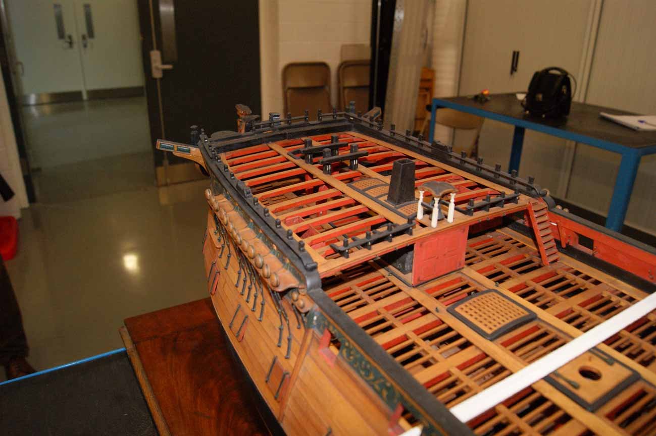
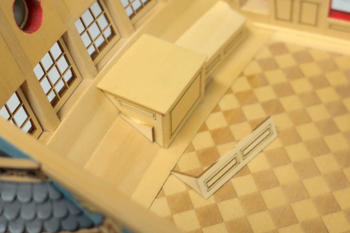
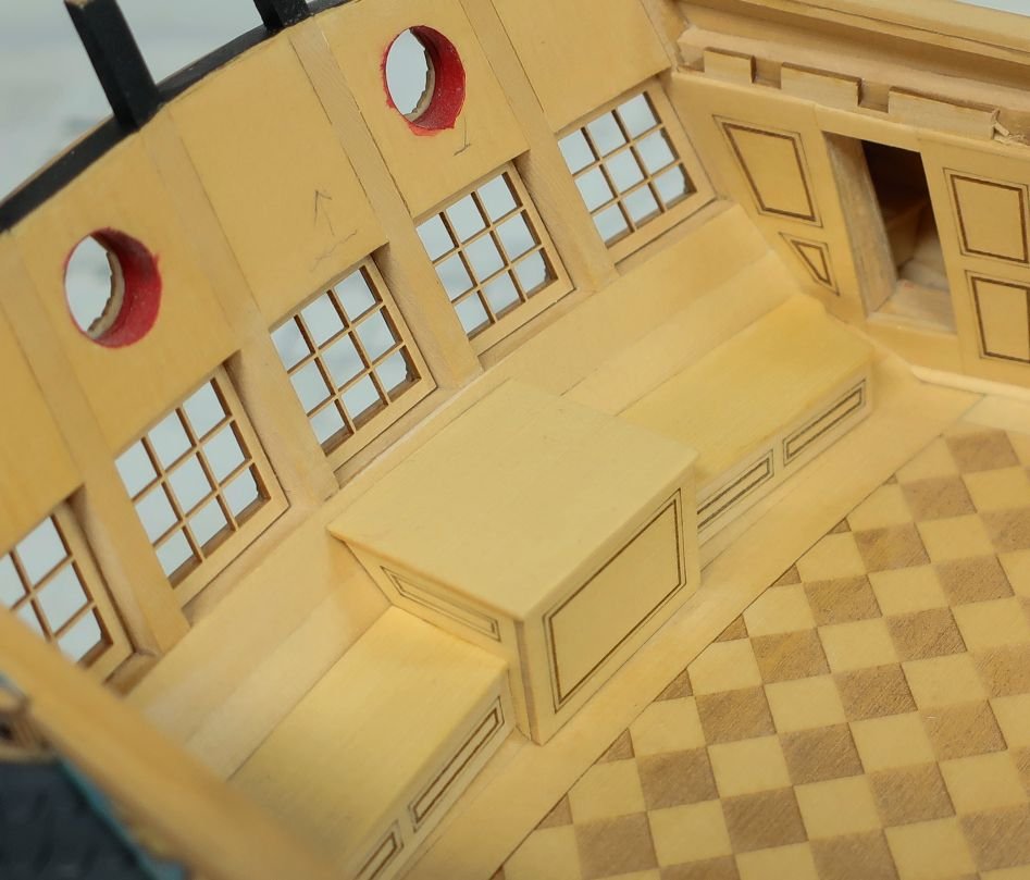
The benches are pretty simple as well. You just want to follow the curve of your transom. This might be different slightly from model to model. First, you add one of the bench sides to the side of the rudder trunk. See below. Note how the top aft point of the side is even with the break along the inboard counter. At the same time, assemble the front panel for the bench with the other side. Have it ready to glue into position. It will sit on top of the lower counter. But you can see how the front panel is actually up on the lower counter and not actually on deck. This is correct. The benches will not extend all the way to the bulwarks. keep in mind that the bottom of the front panel is beveled so it will fit snug along the forward edge of the bench on top of the curved counter. To finish it off, add the tops of the benches. Bevel the back edge so it fits the counter. It really finishes off the great cabin nicely. The bench tops overhang ever so slightly along the front edge and of course the ends as well.
- 1,784 replies
-
- 38
-
-
-
- winchelsea
- Syren Ship Model Company
- (and 1 more)
-
It would have but I like to try new stuff. These are also a lot longer than on Cheerful. But in the end when done carefully and cleanly it looks the same. Just another way to do the same thing.
- 1,784 replies
-
- 5
-
-
- winchelsea
- Syren Ship Model Company
- (and 1 more)
-
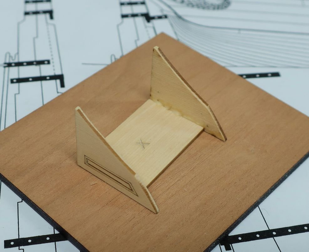
Thanks The rudder trunk is pretty straight forward. Parts are all laser cut but will probably require minor tweaking to fit everyone's model perfectly. There is a laser cut rectangular build jig marked with an X. This is to help you build it squared up. The two sides are glued to this first as shown below. But before you do....test fit each side panel at the stern to make sure it fits. Make adjustments to get it snug against the inboard side of the counter. Then glue them to the side of the base jig.....keep the sides at right angles. Then add the front panel....easy - peasy. Then add the top. Keep in mind that the aft edge of the top is beveled so it fits snug against the counter planking. The top also has the slightest overhang and the edges were softened a bit. No hard edges. Its not glued on yet. There will be two benches on each side of the trunk which I will make next.
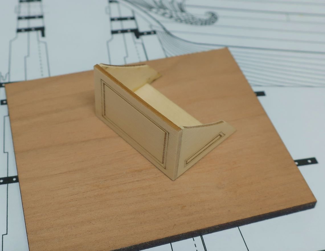

- 1,784 replies
-
- 35
-
-
-
- winchelsea
- Syren Ship Model Company
- (and 1 more)
-
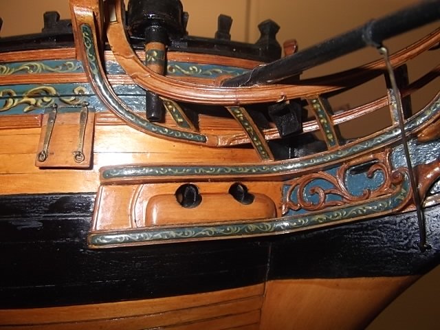
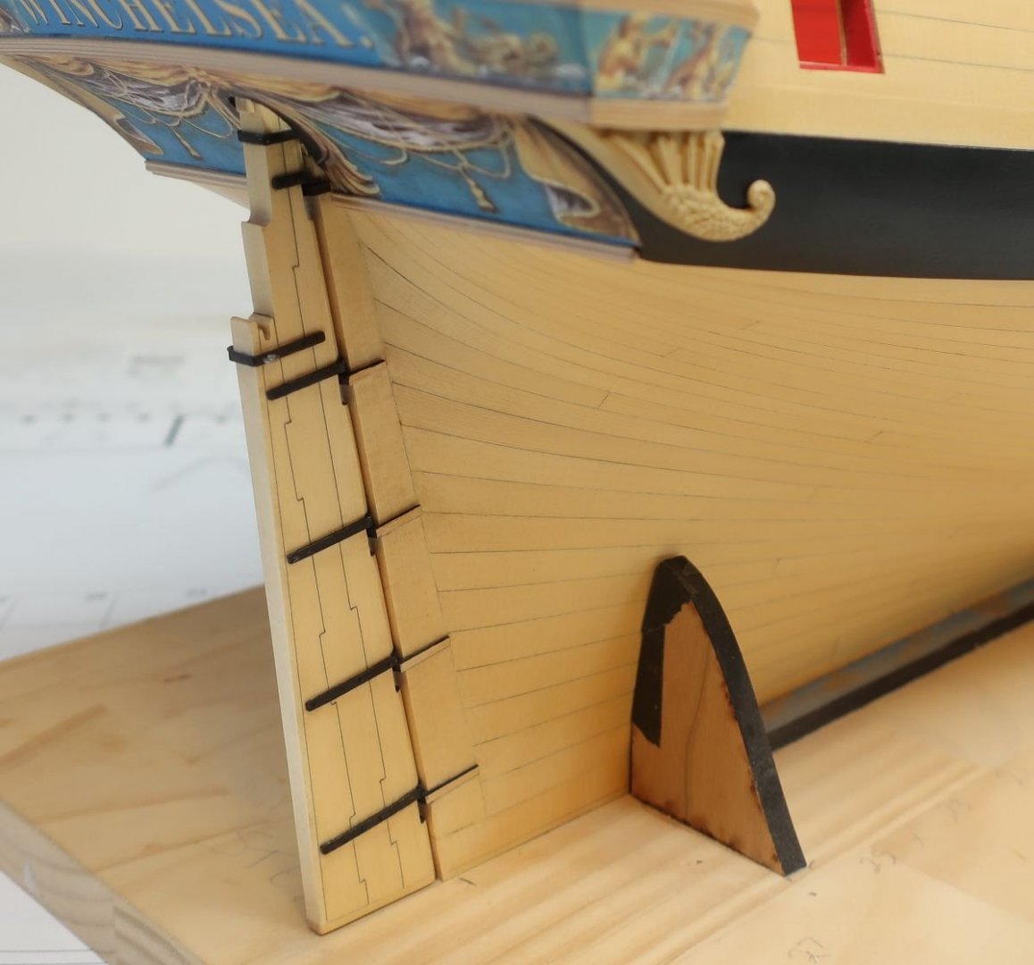
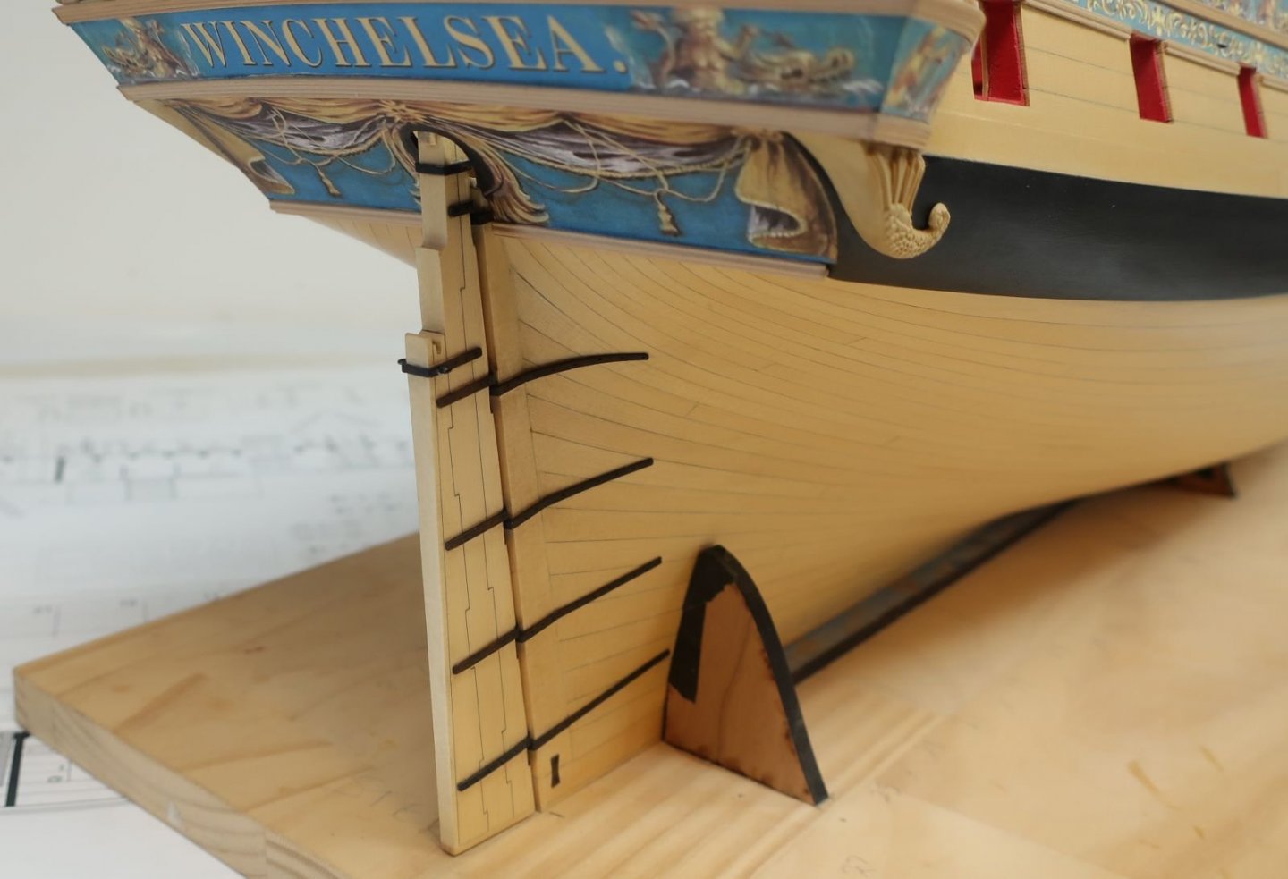
To finish up the rudder and get it installed, it is just a matter of repeating the process of placing the hinges on the rudder post. They are also wooden and laser cut from boxwood. Just make sure you are carful to line them up with their partners on the rudder and angle them properly. See below. Once again the edges were painted black ahead of time. Interesting is the fact that you will have to line up the holes in these so you can hang the rudder in place. That is not an easy feat. But here is a good cheat or trick. You only really need two pins on the rudder to engage the hinges on the hull. Just the top and bottom really need the pins engaged. So you can literally snip them off the other hinges or not add them to begin with. They are not seen and on a scale model dont really serve a purpose. I did this and I bet you cant tell!!! Then add long strips of 1/16" x 1/32" boxwood just ahead of the hinges to use as the straps. Take their lengths from the plans. This is just as we did on the rudder itself. Paint the edges of the strips black first. Once glued onto the hull with the angles all matching, you can sand them all down thinner so they look in scale. Again, once painted and weathered they will look like metal pintels and gudgeons. But look at the photo below. At this stage I marked in pencil where the bolts should be. Then I drilled holes for the black monofilament. I used a #73 bit. Insert the black 20lb fishing line into the holes and snip the ends off leaving them stand proud to simulate the bolt heads. Here is the finished rudder with bolt heads. Its painted black and weathered a little bit. Also notice the small bowtie plate under them. This is laser cut for you out of laser board. Bolts were simulated on this as well. I also added the horse shoe plate at the bow along the gripe. This is also laser cut for you. A bit of weathering powders were used here also. That is it for this update and now I will start on that rudder trunk and benches inboard in the great cabin.


- 1,784 replies
-
- 46
-
-
-
- winchelsea
- Syren Ship Model Company
- (and 1 more)
-
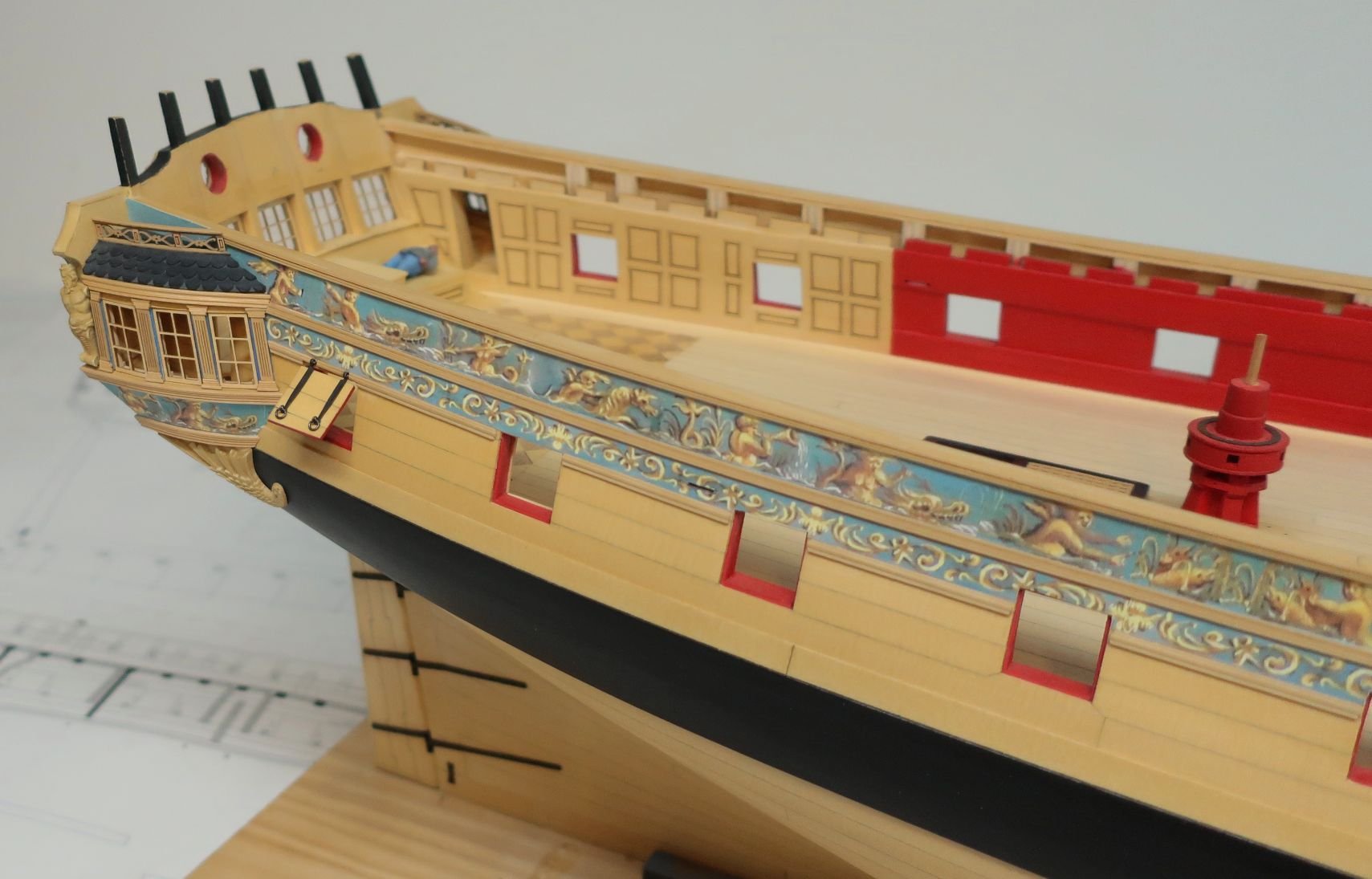
Thats coming along fine.....There is a PDF of the friezes in the downloads forum. You can print out as many as you need. Just print them on plain printer paper. Same is true for the flags and other details and templates.
-
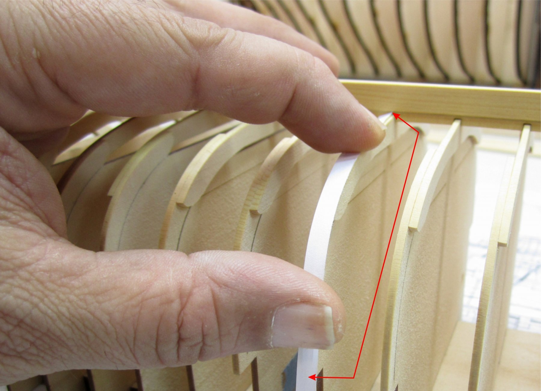
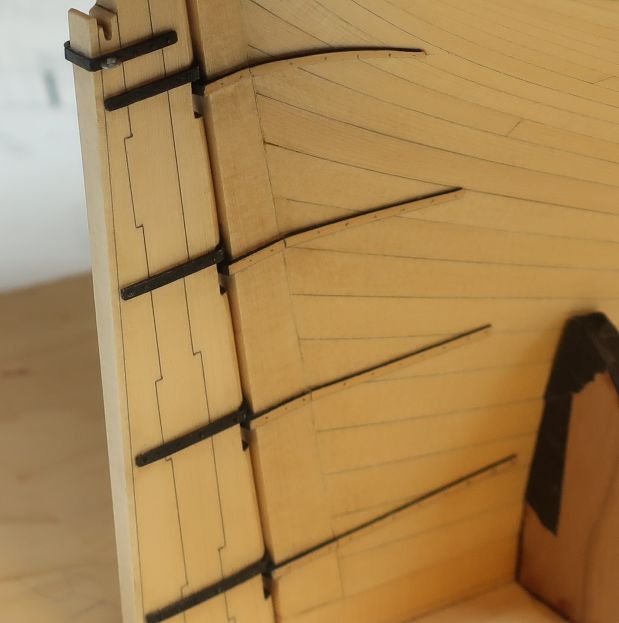
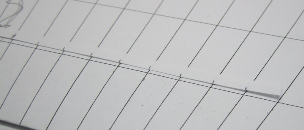
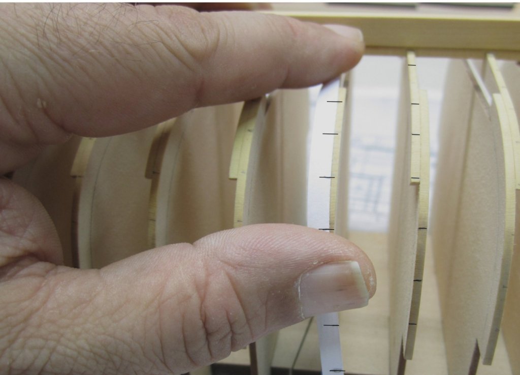
Nope...its 9 planks. With the end of the tick strip also falling on a line....see below. Cut some thin tick strips from paper. Hold them along the edge of the frames with the end of the tick strip against the keel rabbet. You will need to mark the overall length of the frame from the keel rabbet to the sheer. Its very easy to do. ...Take that tick strip and lay it on top of your planking fan. Because we know that this area will need to be split evenly into nine planks, its just a matter of sliding down the fan until it fills the space up. Then mark the strip with 9 tick marks. with one end of the strip against a line. The black horizontal lines on the planking fan were just put there so I have some reference to help me keep the strip level rather than angled. ..Take that strip back over to the same frame and transfer all those tick marks onto the frame edge. All of the frames have been marked except for the three frames at the bow and the three frames at the stern.

-
That is too soft in my opinion for ship models. Even softer than basswood.
-
Looking excellent!! A very nice Syren. 😀
-
Looks good. Cover the stem with heavy tape or some painters tape to protect it while planking.