michael mott
-
Posts
5,200 -
Joined
-
Last visited
Content Type
Profiles
Forums
Gallery
Events
Everything posted by michael mott
-
 Bob, I read somewhere that it is to reduce water hammering. i cannot find the reference right at the moment though. Thanks to all for your kind remarks and for all the likes. Michael
 -
ancre Le Coureur 1776 by obi - 1:48 - lugger
michael mott replied to obi's topic in - Build logs for subjects built 1751 - 1800
Hi Robert I just came across your build today, your hull and blocks are very nice. Michael -
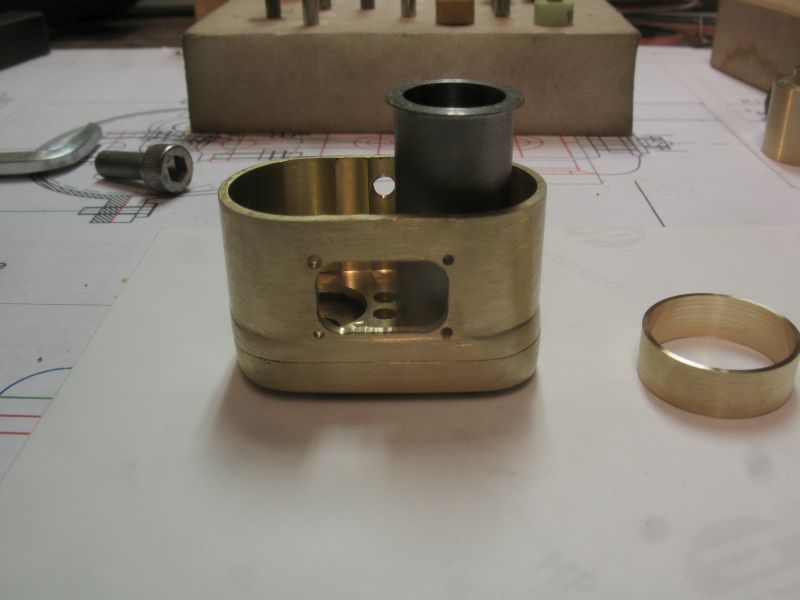
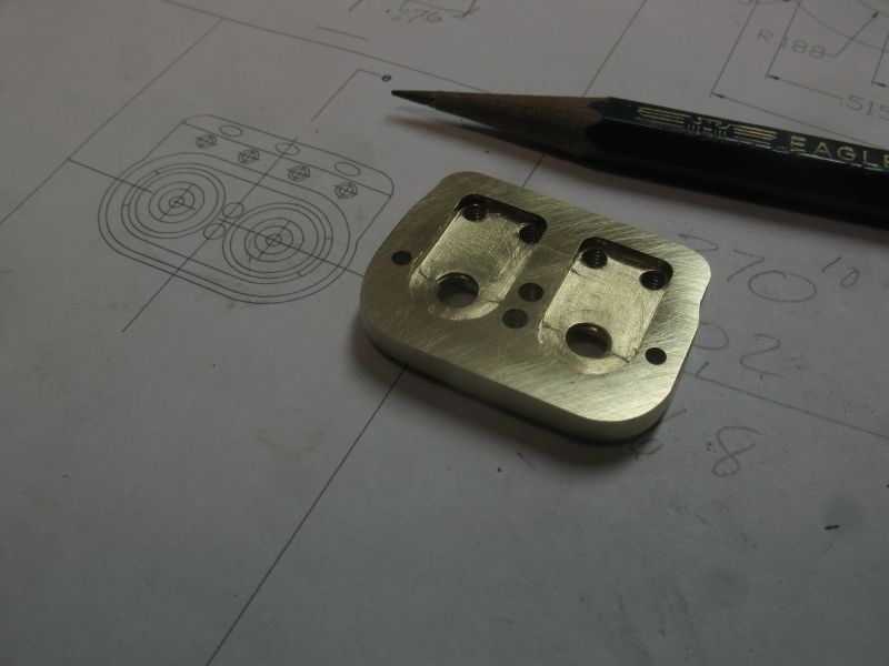
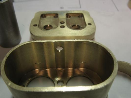
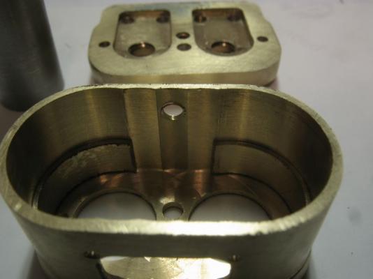
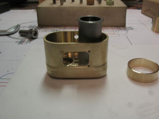
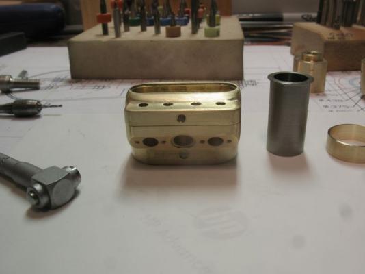
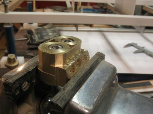
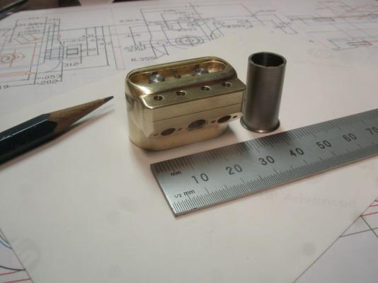
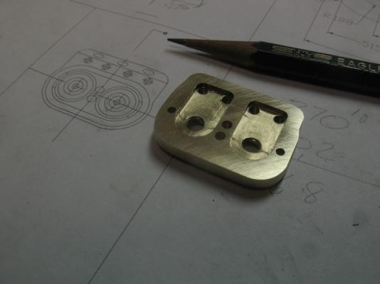
Thank you all for the likes. Brian, Jack, Mark thanks for the kind comments. Ed the more I think about laminating the ribbands the more I like the idea. I discovered that at this small scale there is little room for error. When I removed the support plugs today after finishing the shaping and a few more holes for the water inlet and inspection hole in the front side, I saw that the port holes had in fact penetrated the wall of the water jacket. the space inside the jacket is large enough that I decided to add a plate that will get sweated in place. the first picture shows the two crescent shaped holes from the port drill breaking through the wall. The sleeve insert is machined from some hard 3/4 brass rod the wall thickness was .020" I sliced off two rings then cut those further to just fit enough that the curve is slightly greater than half the diameter inside. By doing it this way they are snug enough that they do not fall out. The next picture shows the inspection hole which still need cleaning up and the cylinder liner positioned to show the water circulation cavity. I will make the base plate before the liners are finalized. It has occurred to me that I will need a pretty good filter system to keep any debris out of the water system. The next photo shows the top of the cylinder with the head removed the holes still need to be reamed 13/32 for the stainless liners. I am still contemplating making these two parts able to be separated I think I have enough space to add some small long bolts up through the water jacked that way they would be hidden. I think I need a break from metalwork and do a little whittling of the boxwood stem and sternpost. Michael
-
Remco The tabled joint is what sets your work a cut above, and demonstrates excellent craftsmanship. Michael
- 1,215 replies
-
- 1
-

-
- sloop
- kingfisher
- (and 1 more)
-
Steve just plain old "elbow grease" files , wet and dry 400, 600, and steel wool. The files are what do bulk of the work. The hard brass might also contribute. I notice that some brass is more yellow and gummy. This brass is nice to machine and work with hand tools. Michael
-
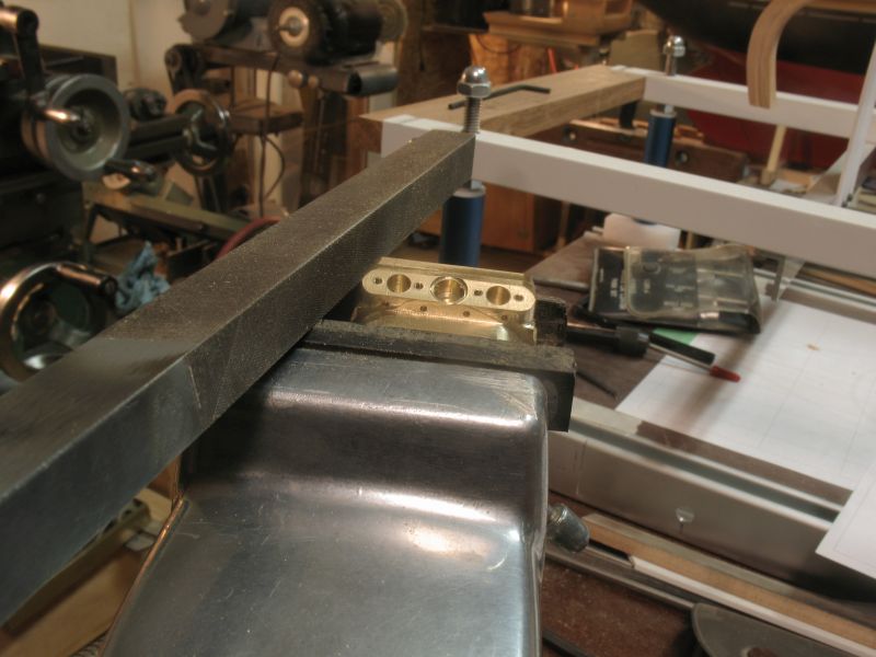
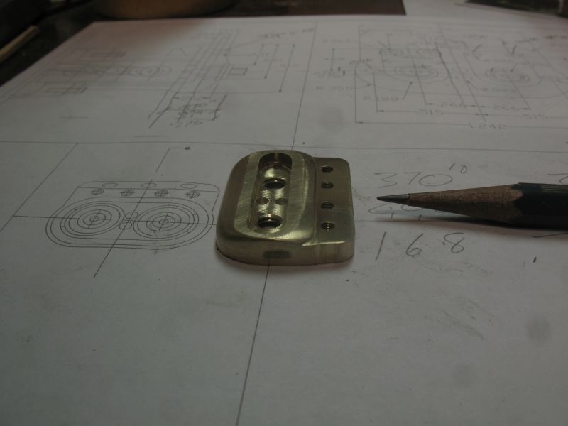
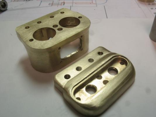
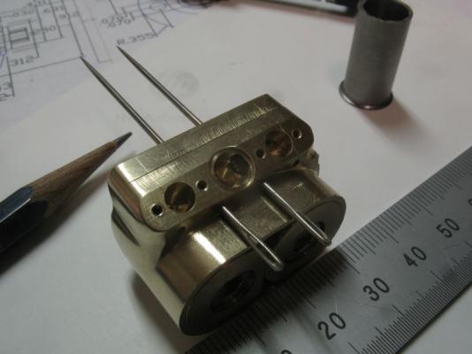
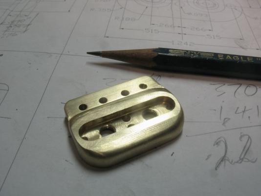
Thank you for all the likes, And Bob and Steve for your comments, its been a long couple of days fiddling with some finicky numbers, I had to make a couple of small modifications to my Mill Drill so that I could use some dial verniers as read out dials for the table travel. I had already set up the depth one a few years ago and because I have slip dials on the mill I have been able to manage up until now . However machining these tiny dimensions with a centre Zero was challenging to say the least. so now I can clip in the vernier and use it as a poor mans DRO (digital read out, only this is an Analog read out ) First I cut a piece of 1 inch square brass and then re cut it to 1.375 x 1 x .625 inches the first task was to bore the main holes to form the inside of the water jacket shell these are .625 diameter and almost 5/8 deep. then bored the holes that will mate with the combustion chamber in the top piece. After the big hole were machined I flipped it over to reduce some of the metal and then machines the small holes for the valves and water passages to the top part of the head. Next I made a couple of support keepers out of some 3/4 diameter brass rod to fill the bore holes and reduced the diameter at the top to use as location stubs for the top part this also allowed me to thread some 10 - 32 cap screws through the spark plug holes to hold the whole shebang together. after the inlet and exhaust ports were machined which seemed to take forever, I was finally able to get on with some finish filing. I like to have a ground safe edge on some of the files it really helps to keep things square The parts are beginning to look like the top of the engine. The valve rods will be fabricated from some largish sewing needles these are .046 inches in diameter which works perfectly, they obviously need some work yet. Time for a break. Michael

-
Jeff you need to look for images of ships moving through the waves like these Michael
-
Good to see that you solved the stanchion issue. The hull does look very nice with the extra keel and the fairing. Michael
-
Very nice Gaetan, your work looks so sharp and clean. Michael
- 728 replies
-
- 1
-
-
- le fleuron
- 64 gun
- (and 1 more)
-
I am finding it difficult to come up with the right words to describe my admiration of your fine work Ed, not speechless but darn close. Those last two photographs show just how fine an Artist with wood you are. Michael
- 3,618 replies
-
- 2
-
-
- young america
- clipper
- (and 1 more)
-
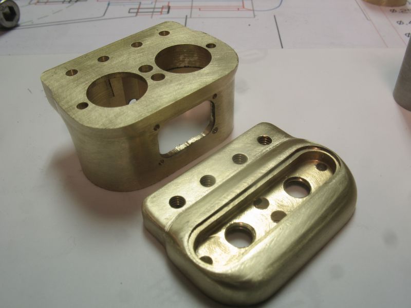
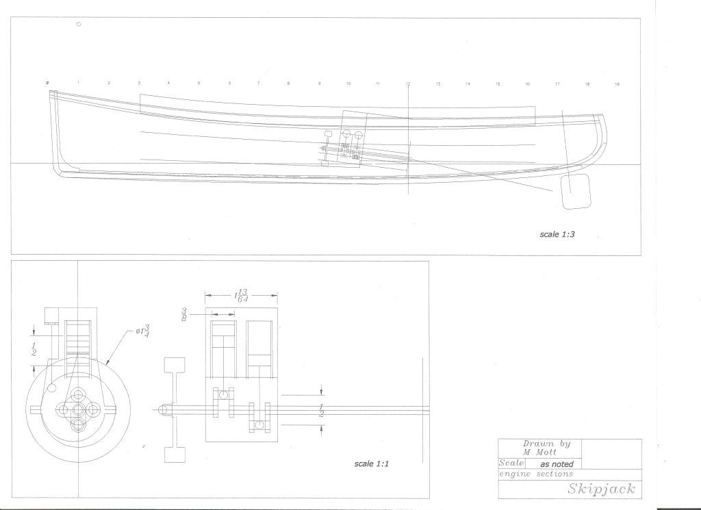
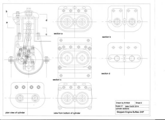
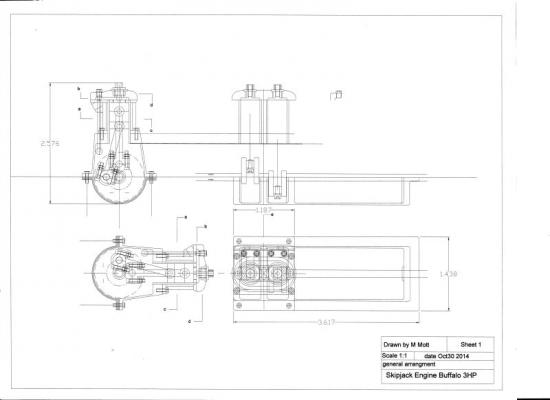
I have been doing some research into the whole engine building aspect of this little launch. I made the top part of the engine this evening it still need a bit more work to add the top plat to seal in the water cavity the spark plugs will thread through the plate into the main body thereby allowing water to circulate around the part that goes through the cavity. This drawing shows the section through the engine and sections through the cylinder head. Buffalo 3HP sheet 1.pdf this is the top part of the head Buffalo 3HP sheet 2.pdf And the brass part I made today Michael

-
Tricky bit of work there Jeff. Michael
-
CAD software
michael mott replied to cog's topic in CAD and 3D Modelling/Drafting Plans with Software
Jud Thanks for the info I shall have a look. although I have been using my Auto-Cad LT 2000 for 14 years now. Michael -
CAD software
michael mott replied to cog's topic in CAD and 3D Modelling/Drafting Plans with Software
Jud Brought back many memories of my frustrations with the first version of Autocad Light. I really likes the simplicity of Generic Cad it was too big a competition for Autocad so that is why they took it over , they had 2 updates if my memory serves me correctly, them stopped because they introduced Autocad LT 98, which was an absolute dog to use in my opinion, One day I overheard some chaps talking about the new Autocad Lt 2000 and how easy it was to use, I tried the newer version and found it to be much better. and because the generic was not being supported I switched. I still miss the simple two finger commands of Generic though "rd" was one I used a lot it is fading from memory now though. Michael -
Omega that is a sweet looking hull, could easily be a launch for a bigger three master ya know!
-
Bob my understanding from Steward is that as the planks are going to be placed the ribbands are removed one by one as the planking proceeds. the link is to a series of pictures showing the method. Michael
-
Hi Bob I must have been writing when you posted. Yes it will definitely pose a few challenges but isn't that what these hobbies are really all about. Research, figuring out how something was built, testing materials for our models, choosing a method to make some small item, sharing our discoveries. the joy of completing a part that meet our expectations. While I have been researching this engine piece I have been ruminating in the back of my mind the specific choices and way that the ribbands will be made, even though they will be temporary they need to be strong enough to withstand the pressures of the bent ribs. One thing that I am contemplating is to use thinner ribbands but laminate a few layers, because the outside dimension can be larger as long as the inside one conforms to the inside shape of the planking. If they are too flexible it will make fitting the ribs much more difficult. In my "Boatbuilding Manual 4th edition" by Robert M Steward book, in the section that covers the preparation of the molds for building the hull it recommends that the ribbands be full length of the hull if possible and only use a join if needed at the least curved part of the length. My ribbands can be cut from material that is only 32 inches in length so the joining longitudinally is not an issue. I do not want to put a lot of bending stresses on the thin plastic bulkheads so by making them thicker by laminating layers might prove to be the best option. I will be tying them to the bulkheads with very fine copper wire which should not interfere with the layers. Michael
-
Hi Steve, yes I am going to make my own, yesterday I went to the city to a large model supply store, I was disappointment with the answers to the questions I had regarding spark plugs and basic information about model engines. I also asked about book and was told that there is this thing called the internet. I did save the trip by purchasing some 3/8 dia 6061 aluminum alloy and some 1/2 inch diameter stainless steel rod. came home and looked up "how to make miniature spark plugs" on the web that was how I found that model engine site. I stayed up way too late reading as much as my eyes would allow but now feel much better about the decision to build a proper engine for Skipjack. Thanks for all the likes. Michael
-
Carl, Steve thanks for stopping by. Steve I think that you are correct but I need to learn more about these old engines. This site has some interesting engines the one I linked to has cylinders that are 3/8th bore by 1/2 stroke which is very encouraging. Michael
-
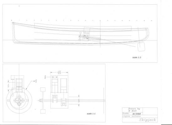
A small update The concept drawing of the size of the engine and location. Michael
-
Steve all that electronics and wire just baffles me, the sails look great and that you can now controle them well is very good news. Michael
-
Mark Taylor, Dan, Mark, thanks for your kind remarks, and to all who are following along with likes. Today I learned a little bit more about the engine, and will be getting more pictures and measurements in November from Roger. The Engine is a 4 cycle with Buzz coil ignition just like the old Model "T" This will make the build easier because I will be able to use simple fuel and not fuel with oil added as in a 2 cycle. Michael
-
Mark those scrolls will be exquisite. Nice drawing, and thanks for the kind words in Skipjack. Michael.
-
I will be following along. Michael
-
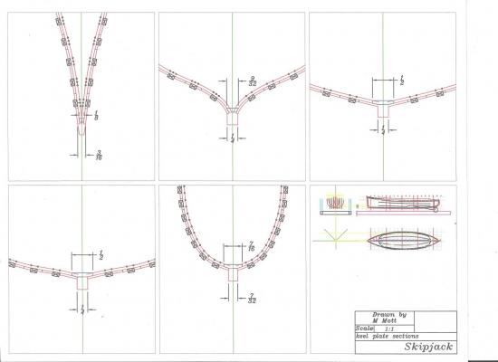
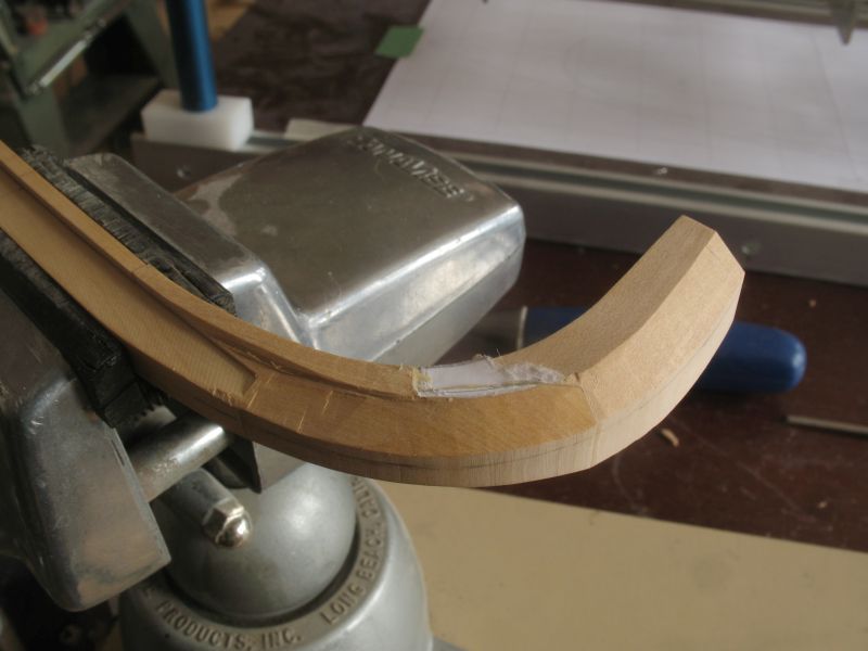
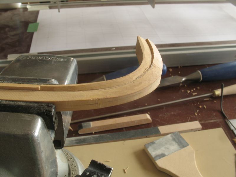
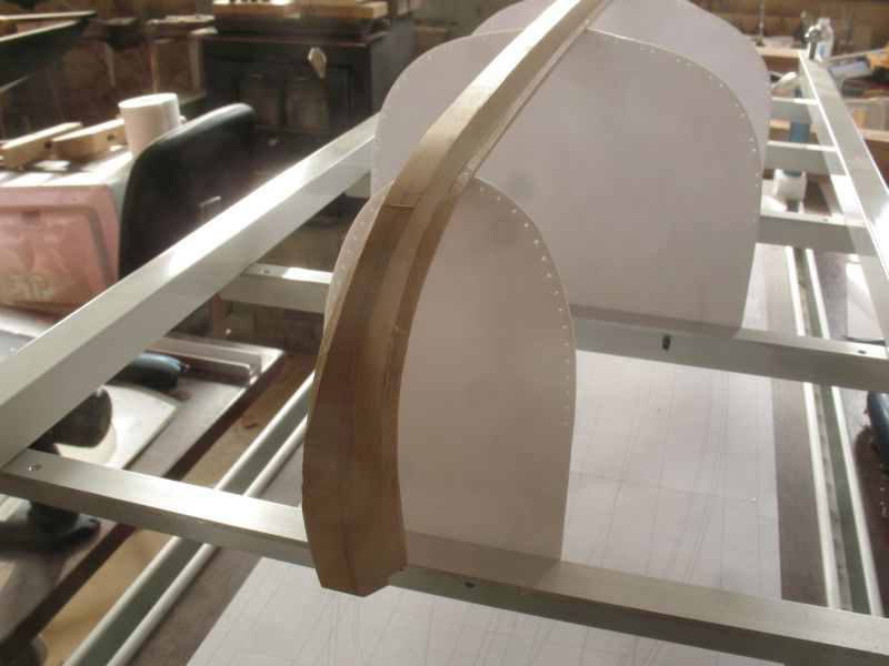
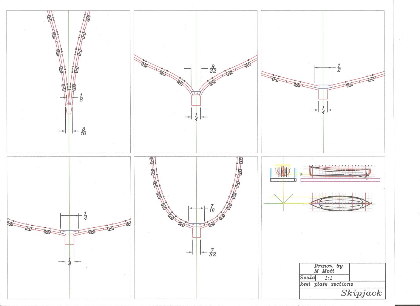
Just a little more progress carving the sternpost on the port side, I am taking this very slowly. This feels like a tricky detail but to all you full keel three mast shipbuilders it probably looks like child's play. this is much more difficult than the keel on the pilot cutter. Here is a drawing showing the keel at each of the building stations A sincere thank you to all who have pushed the like button, I really appreciate it. Michael