Check out our new MSW Sponsor Innocraftsman
×


michael mott
-
Posts
5,195 -
Joined
-
Last visited
Content Type
Profiles
Forums
Gallery
Events
Everything posted by michael mott
-
 Hi Steve that is a great solution to the keel issue. I find it interesting that we all seem to have these "if I had to do it all over again what would I do" conversations going on in our minds. Ask any builder on this site that same question and there would no doubt be some very interesting answers and solutions to the challenges we set ourselves. Michael
 -
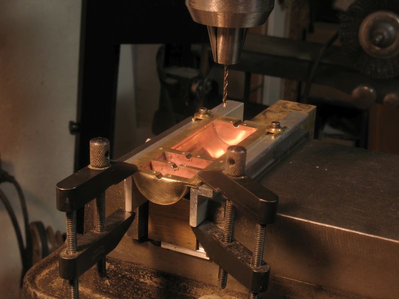
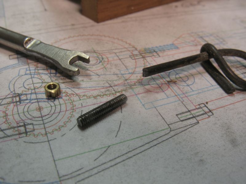
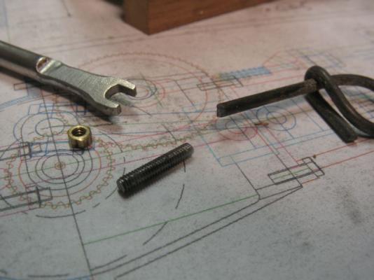
Thanks to all the builders who pushed the like button. Denis, I am learning a lot about engines myself at the moment. Steve yes I am going to make the reverse mechanism as well. Today this morning I was drawing up the feed-water pump, I ended up finding a good internal design in one of my old Model Engineer mags page 1265 October 1981 for a 3 1`/2 inch gauge Stanier 8F. I will need to make it smaller but the design will fit into the pipes that are on the prototype buffalo which pumps off the camshaft like this one on the Old Marine engine site I worked on the pan today and roughed out the half round bottoms for the crankshaft and drilled and tapped all the 0x80 holes for the studs. I looked at all my stashes of steel wire and rods looking for some .060 to make the steel 0x80 studs from. I could not find any that was exactly .060" I then came across a most unlikely source, the re-bar ties left over from building the house just happened to be .060 the stuff threaded up a treat. had to make a small open ended wrench to get to the valve side because of the overhang. Did a test fit of the crankcase and pan and water-jacket, it all slipped together nicely. It has really helped with the accuracy of cutting and drilling to set up the dial calipers on the mill, and working from a 0 centre Michael

-
Hi Steve the extra length serves as a housing for the reversing clutch for the prop. like this one on the old marine site Thanks for all the likes Michael
-
Sounds like things are going well Walter. I look forward to seeing the final results. Michael
- 208 replies
-
- 1
-

-
- meridea
- repair ship
- (and 1 more)
-
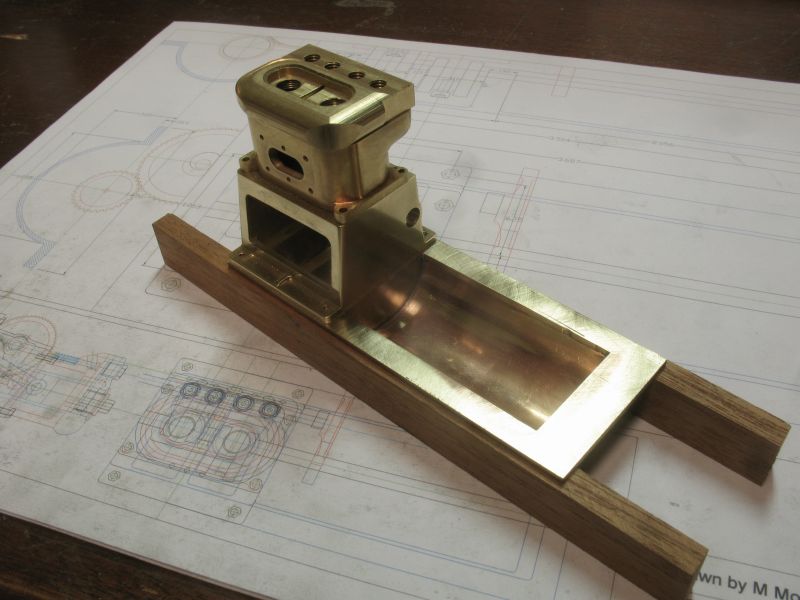
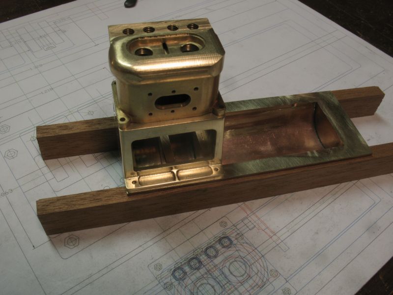
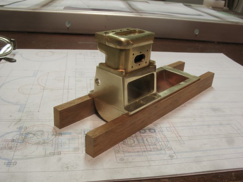
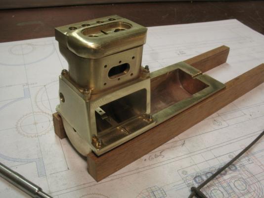
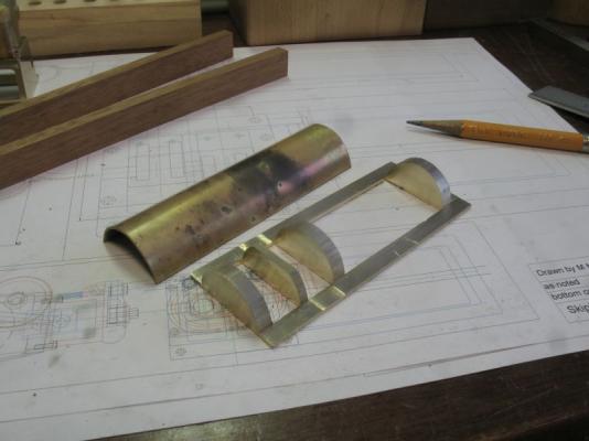
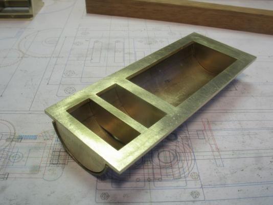
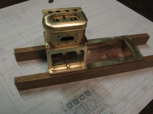
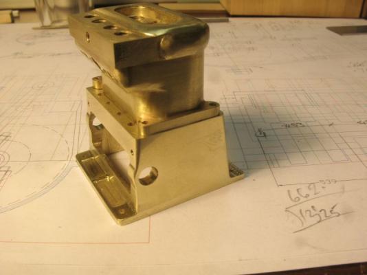
Ed hopefully the next set of pictures will clarify my description. Mark well it is not a complete machine job there is some soldering however I did not want to anneal the brass that has the bearings braces so opted for soft solder which will be more than adequate for the oil pan. The first picture shows the material being removes that will become the hollow areas'some parts were machined by the numbers and the bulk was just milled away by eyeballing it. Next the 1/32 thick sheet was annealed and curved over a steel bar. It took a while to get it fitted cleanly, the flat area on the middle bearing wall is to allow the oil to pass through to equalize both chambers. The next picture shows the assembled parts cleaned up a bit getting ready to do the soldering. Resting the upper part of the crankcase to see the overall scope of the whole engine. In the next picture you can see the central cross member. There is still a fair bit of cleaning up to do but I am generally pleased with the progress. Again thanks to all who have looked in and pressed the like button. Michael


-
Well Ed, you could have fooled me. I agree with Greg the like button have to give way for a comment regarding the quality of this build more often than not. Yes and enjoy the thanksgiving time, we all harvest what we sow. Michael
- 3,618 replies
-
- 1
-
-
- young america
- clipper
- (and 1 more)
-
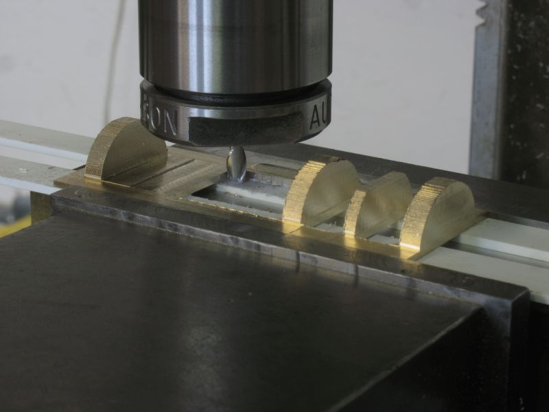
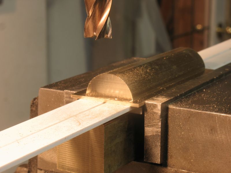
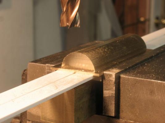
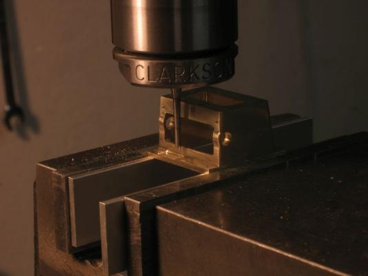
Set up the table of offsets to machine the curved inner surface of the oil pan, and after two hours of cranking the block back and forth the shape slowly emerged. I lowered the cutter .010" for each pass. Next I will cut away the negative areas where the cranks will rotate and either side of the bottom of the crankcase then flip it over to finish off the bearing recesses. then a brass shell will get soldered onto the cross members, creating the hollow shape. I made it this way because I was stumped as to how to get the inside shapes of the oil pan, I suppose I could have set up a boring bar and scooped out the recesses the only issue with doing it that way was being able to have an opening underneath the central bearing beam to allow the oil to move about in the bottom and equalize rather than being isolated to each recess. the other advantage to making it this way is is that I will be confident that the wall thickness will be consistent. Thanks for the likes. Michael
-
Nice recovery Chris, and a great job laying out the planking. Michael
- 144 replies
-
- 1
-
-
- corsair
- bermuda boat
- (and 1 more)
-
Nils I have to agree with Keith regarding getting lost in the amount of detail in those last pictures. She is looking rather spiffy. Michael
-
Seems that gears are in the air today, nice work Denis. Michael
- 956 replies
-
- 1
-
-
- andrea gail
- trawler
- (and 1 more)
-
John what lovely lines she has john and great to see an update. Michael
-
Thank you all for the very encouraging comments they are really appreciated., I have been doing a lot of calculating this morning because it looks like the gears for the timing are 64 teeth and 32 teeth respectively. I do not have dividing plates for my rotary table and so it makes sense to use divisions of 360 for making the gears. all the standard gears that are in the ball park for the diameters that I am locked into are not the correct ratio of 2:1. 64DP comes the closest,. I have decided to bite the bullet and make them to a DP of 75 which gives me 60 teeth and 30 teeth for the diameters that I need so now I also need to make the gear cutters for both sizes which means a number 3 cutter and a number 2 cutter. My 48 DP cutters which I made a few years ago are just too big. There is a great article in the Model Engineer October 1 1971 issue by D J Unwin on how to make gear cutters with all the formulas for making them. each cutter require a separate tool to make the cutter, They are simple tools but it is an extra step in the chain. Thanks also for all the likes
-
Row thanks for you very kind remarks, regarding the cabin sides the part that I am concerned about is the pine sides that are dovetailed, the cabin doors which are mahogany would remain as bright work as would the cockpit. Regarding the free sailing, there is a fairly large area that is designated and roped off for swimming and at the appropriate times it would be a good place to sail her, the depth is also Ok and the bottom is smooth and sandyish there. Owen very nice work on the model, what did you do to achieve the caulking on the decks? Thanks to all for the likes. Michael
-
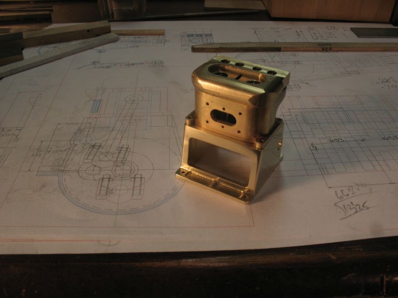
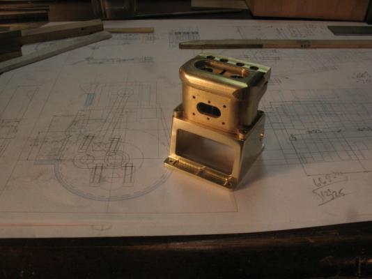
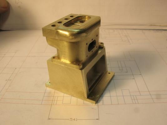
Thanks for all the likes and encouraging comments. I had to make another cutter to make the recesses in the main flanges I have already drilled the holes to accept the camshaft bearings they are larger because I need to be able to clear the raised cams. An overall shot of the progress to date. A close up of the new cutter, I needed a long reach with a small diameter cutting edge to fit next to the body of the case. it is hardened drill rod the diameter at the cutting face is .086" The bolt holes are .060 and the case it tapped ready for the 0x80 bolts. Michael
-
Truth be told I bet many of the members of this site have felt the same way at one time or another. I know I have felt this way at times. Michael
-
Thanks for taking the time to assemble a build log Dan. The size looks about normal to me Michael
- 18 replies
-
- 1
-
-
- lullubelle
- yacht
- (and 1 more)
-
Owen very nice model, do you have pictures of the build? What plans did you use? very nice work on the sails as well. This reminds me, that I really need to get some work done on the cutter as well as my other little distraction. Michael
-
Omega, that dingy is insane, and fantastic all at the same time. great job, and yes i really like the white on the hull of the yacht. michael
- 120 replies
-
- 1
-
-
- mystic
- motor yacht
- (and 2 more)
-
Cutty Sark by NenadM
michael mott replied to NenadM's topic in - Build logs for subjects built 1851 - 1900
Nice work on the stars Nenad, i also like the rope. Michael -
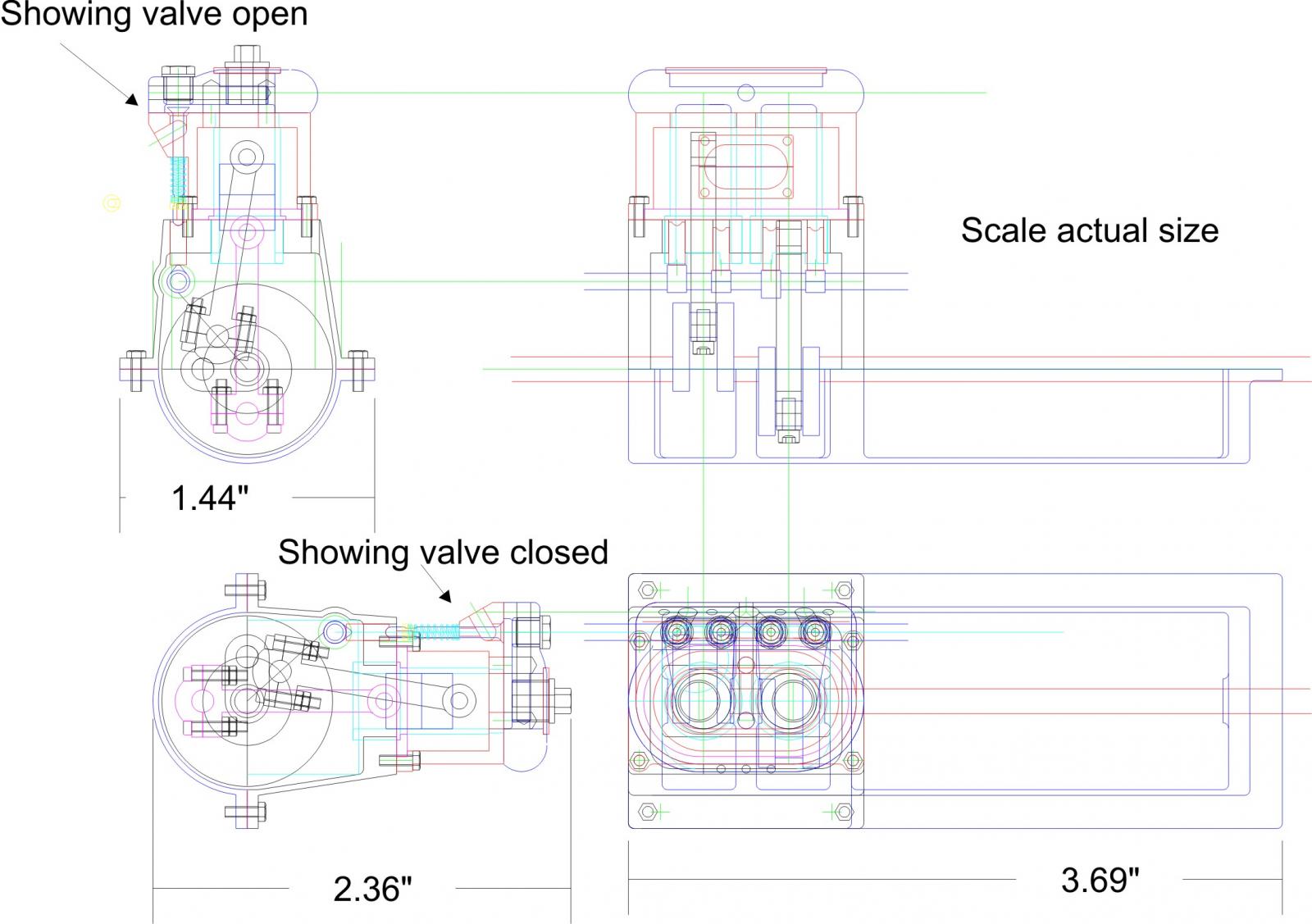
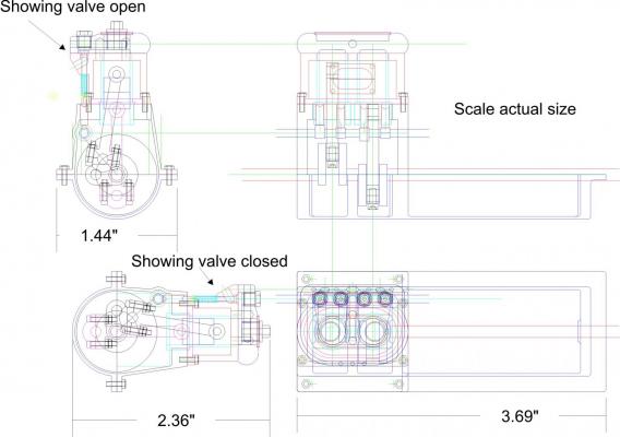
Omega, here is a drawing showing the cross section of the engine and the camshaft with the valve in the open and closed positions. valve train.pdf Bob thanks for the compliment, one of the difficulties of working with the small sizes is that when drawing they are as big as the screen and it is a constant effort to remember the real size as I am drawing. when an area looks about right and then I realize that the dimension might be only 1/64th I have to do some rethinking. Michael
-
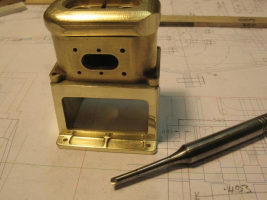
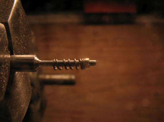
After doing a few experiments with the valve stem springs and keeper, I have increased the diameter of the valve-stem to .060" inches leaving the narrow section for the keeper at .046" This was one of the early tests using the .046 stem the spring is .078 in diameter and the wire is .011. the keeper was a bit fiddly. I can safely increase the stem diameter and still maintain the .078 diameter springs the length of the springs are ..259" presently I am learning how to wind them so that there is a double coil at each end with the wider spaced turns in between. I have found that it is better to make them this way rather than winding a length then stretching it out to form the compression spring. The crank case is progressing well at this time also. there is a fair bit of hand filing to finish up the corners because I do not have the requisite end mills to do all this work on the milling machine. this next picture shows the flats on the sides of the liners slipped through the top of the upper part of the crankcase. that's it for now. Michael

-
David the Kufu boat is one of those that I have thought about for a long time, it is my favourite in Landstrom's "Book of the Pharaohs" also the book "The boat Beneath the Pyramid" by Nancy Jenkins and John Ross. both of which i have spent many hours reading. Michael
-
Steve the valve stems are .046" it is the springs that I will be concentrating on first. Michael
-
Nice work on the balusters Dan. Michael