michael mott
-
Posts
5,200 -
Joined
-
Last visited
Content Type
Profiles
Forums
Gallery
Events
Everything posted by michael mott
-
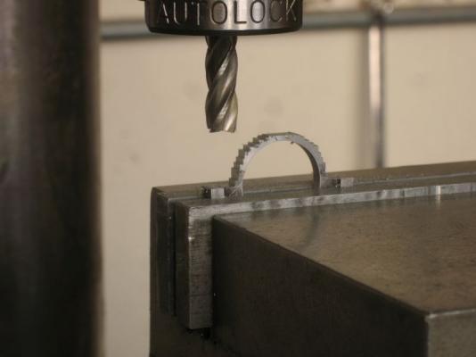
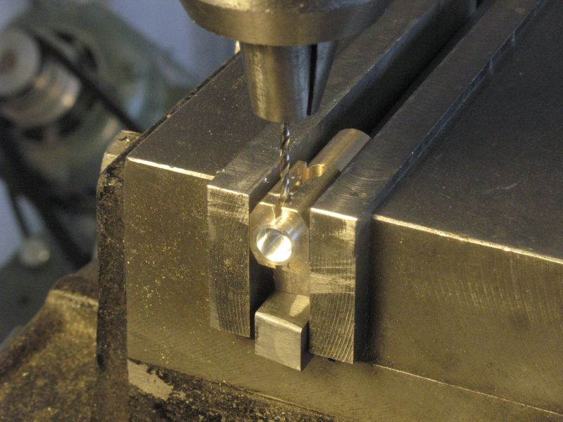
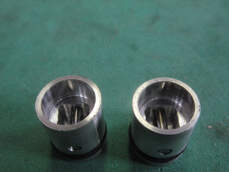
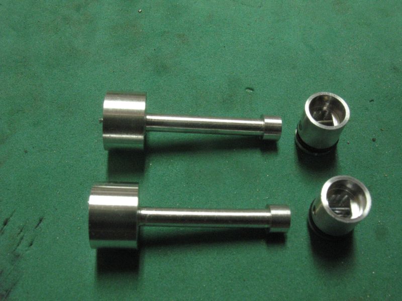
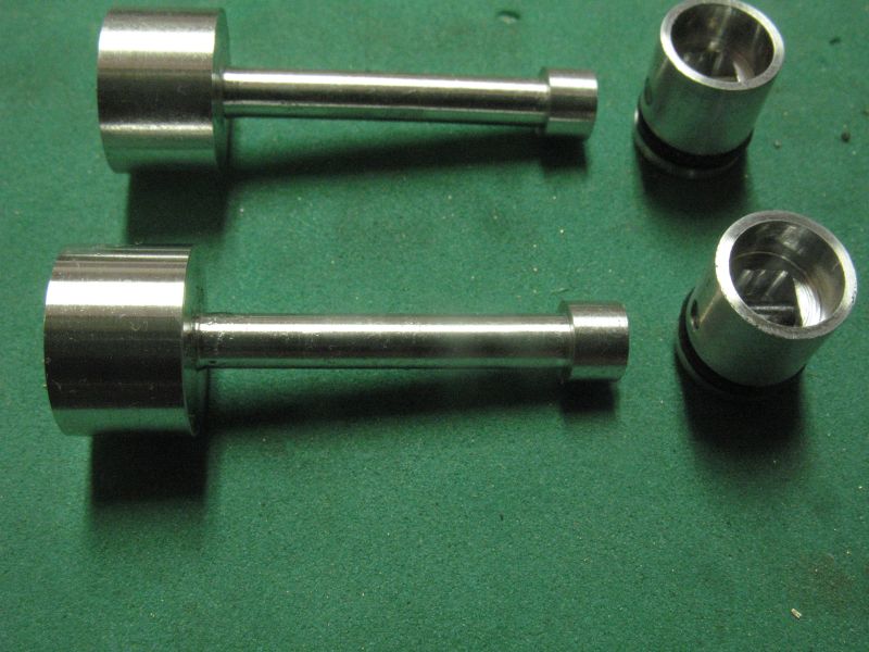
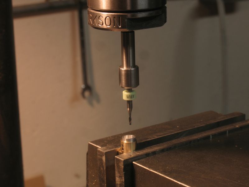
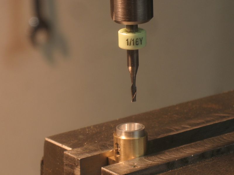
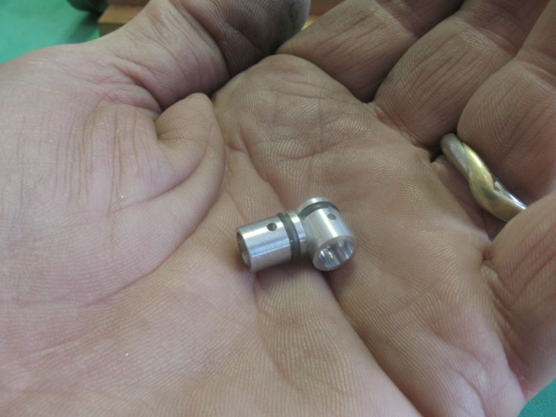
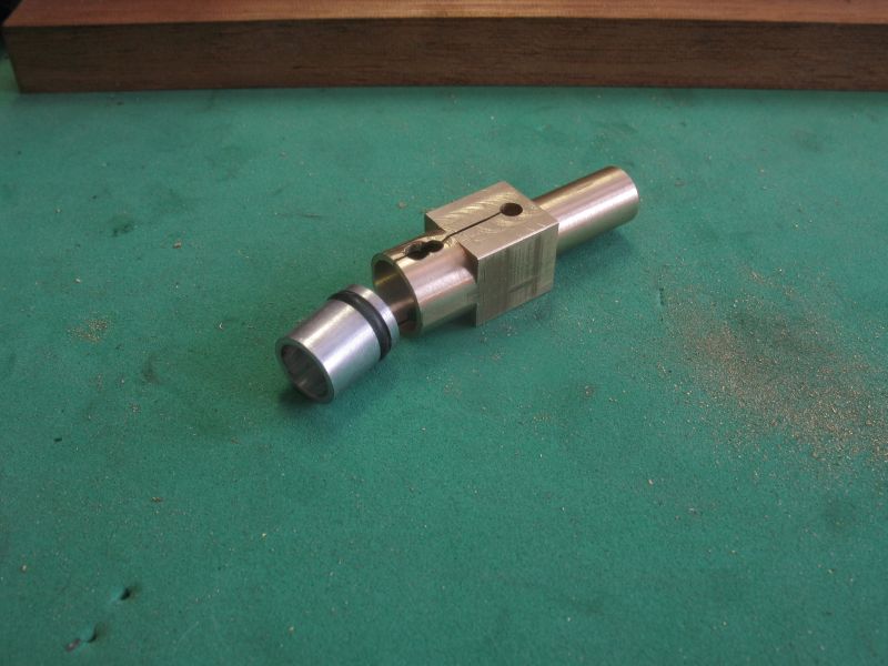
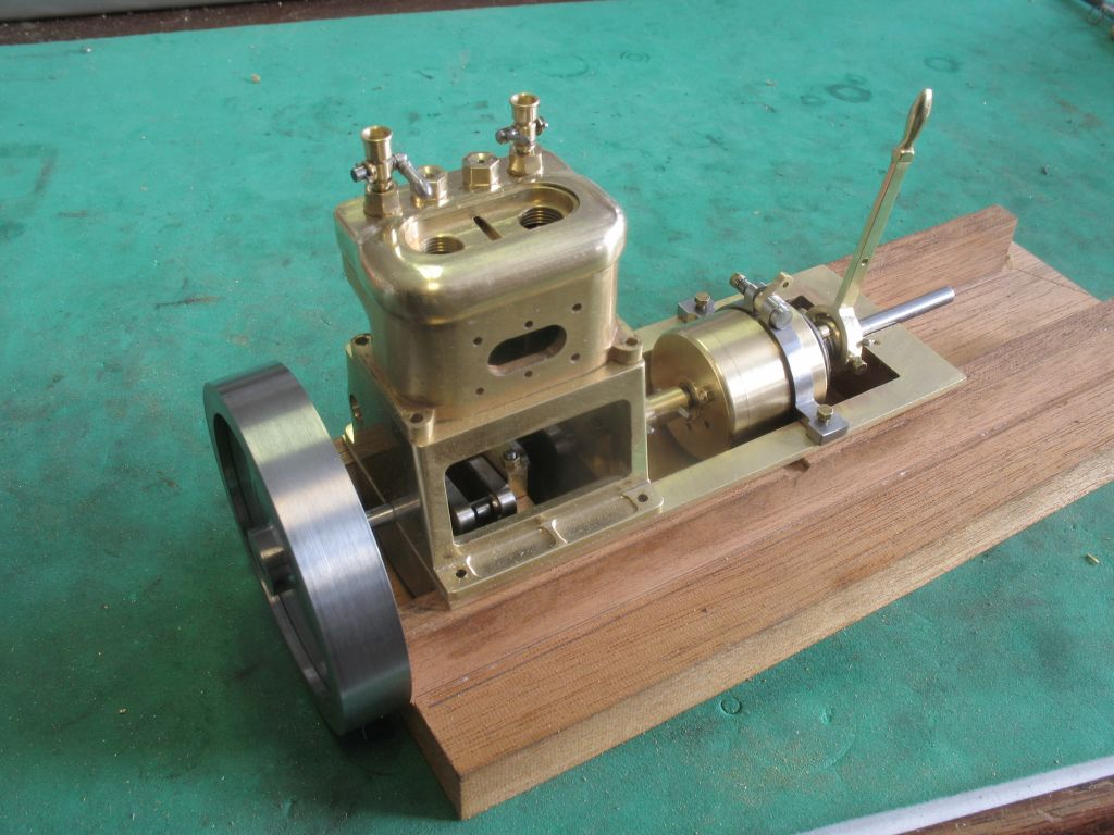
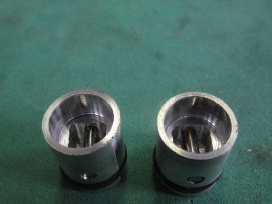
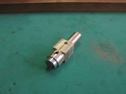
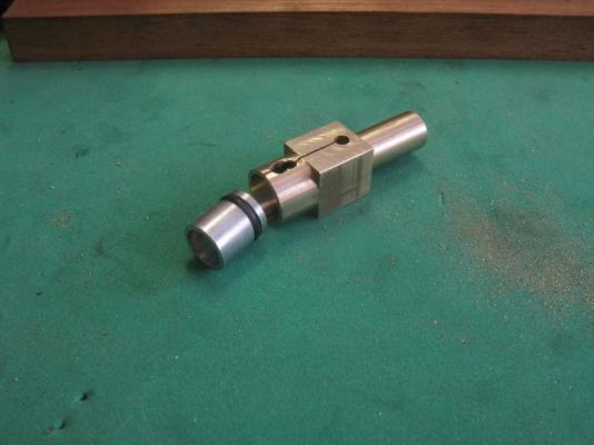
 Steve and Bob thanks for your nice comments, and to all who have added likes. I ended up making a new holder and some new pistons (it would be nice to only have to make something once for a change) The new collet really does help a great deal being able to see clearly what I am doing. the new holder also is a bit stronger, the firdt pic show drilling the 1/16th hole for the wrist pin. the finished pistons with the rectangular cavity and the wrist pins temporarily in place. I have turned down the blanks for the con rods, The next operation on the con rods will be to machine the large diameters into flats, then bore the hole for the crank , and drill and tap the crank end before splitting it with the slitting saw. then the big end will be re assembled and rebored for the big end bearings piston and con rod.pdf Michael
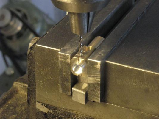

-
So you are telling us that you are taking up watchmaking next Beautiful job and the base is great too. Michael
- 120 replies
-
- 1
-

-
- mystic
- motor yacht
- (and 2 more)
-
looks great Mark nice to see the shape coming together. Michael
-
Nice to see the progress Russ michael
-
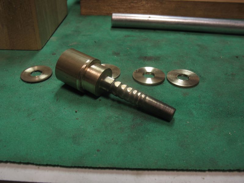
Thanks Denis. Not a great deal of progress over the Christmas, too much food intake and family visiting all very enjoyable of course. I spent a little time today mostly building a special collet for the 1/8th shaft mills and drills which I would normally use in a drill chuck, but using a drill chuck for milling is to court disaster. I used some free machining 3/8 mild steel for the collet, this tool will only be used for light work. First I turned it down to 1/4 and threaded the locking end 1/4 x20 to fit into the 1/4 collet in the Clarkson collet holder for the mill then it was drilled with a #31 drill and reamed 1/8th for the 1/8 diameter shank drills and mills. the end was threaded 5/16 x 24 and the end 1/2 inch was cross slotted with a .014 slitting saw and a 41 degree taper was turned to match the 82 degree 1/4 diameter countersink that I have. A locking nut was machined out of a scrap of 1/2 inch diameter mild steel and a couple of flats filed onto it for a wrench All this was done so that I could actually see what I am doing because with the small diameter end mills the Clarkson collet holder is too big a diameter and really restricts the view when using the small diameter mills. Tomorrow I will do some work on the inside of the piston. Michael


-
Miniture machine screw sizes
michael mott replied to grsjax's topic in Metal Work, Soldering and Metal Fittings
Hi Pat Hornet beat me to the same question. Michael -
Mark thanks. Carl most of the model engines use aluminum pistons including the ones that I saw in the ship engines thread that I linked to. Merry Christmas everyone
-
Mark you can blame the tooth issue on the balmy weather, that you had a bit of sunstroke Merry Christmas Michael
-
Yes Omega a magnificent little bit of work. Merry Christmas Michael
- 120 replies
-
- 1
-
-
- mystic
- motor yacht
- (and 2 more)
-
Even your taking a break relaxing work is superb Doris. A merry Christmas to you and your family as well. Michael
- 883 replies
-
- 1
-
-
- royal caroline
- ship of the line
- (and 1 more)
-
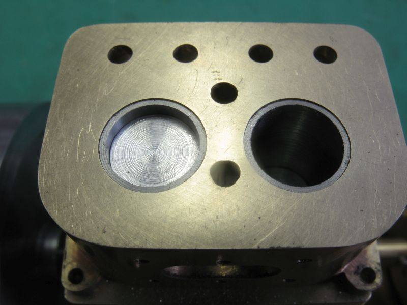
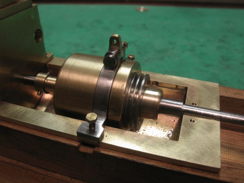
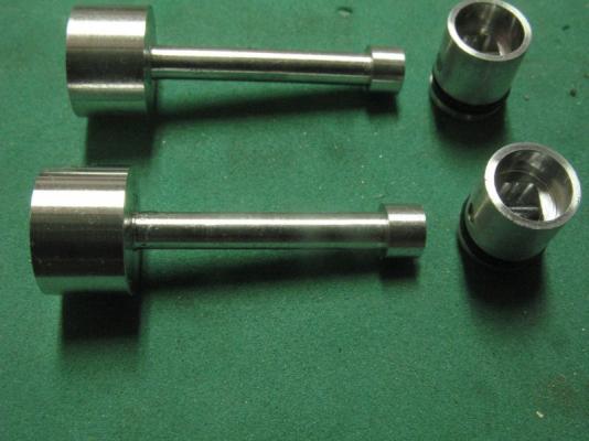
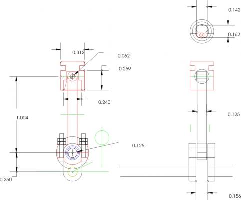
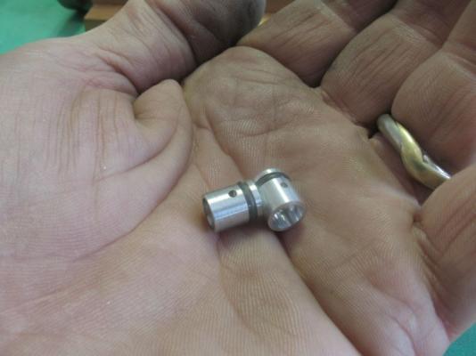
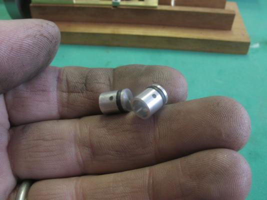
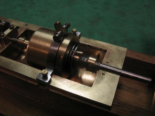
I have got the gearbox to the point where I can now move on to the driving portion of this engine namely the pistons and associated gubbins. First I needed to machine up some blank pistons these are .311" (7.89mm) in diameter and .372" (9.52mm) high these were then set into a fixture to drill the wrist pin holes and to machine the squarish hole inside. they are fiddly little things to work with, popping the O ring on is easy getting the ring off is another story. they slide up and down nicely in the cylinder head. Merry Christmas everyone michael


-
Pen Duick 1898 by Mfelinger - 1:20
michael mott replied to Mfelinger's topic in - Build logs for subjects built 1851 - 1900
Row that is the same model of Pen Duick as this one, that Carlos has posted in the Gallery, he also has been working on a beautiful model of a crabber. Thanks for the link to the video I had not seen that. It also looks like Carlos' boat has a little more free-board that the real one. Michael -
Mark, thanks, once I get this gearbox working smoothly I can move on to the pistons and con rods. Steve, yes the simplicity of the early machinery does have some advantages in the smaller scales, thanks for you compliments. Regarding the bending of the shaft I had not considered it, and am not going to worry about it. Carl, thanks it took a while to get it looking well. Nils, I am thinking that it will run on the fuel used for glow plug engines or Colman camp fuel. Bob thanks. Thanks for all the folk who added likes. I will be doing some more tinkering with the link and lever today. Michael
-
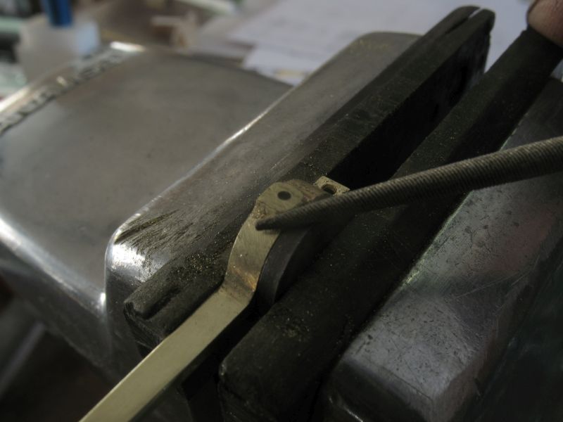
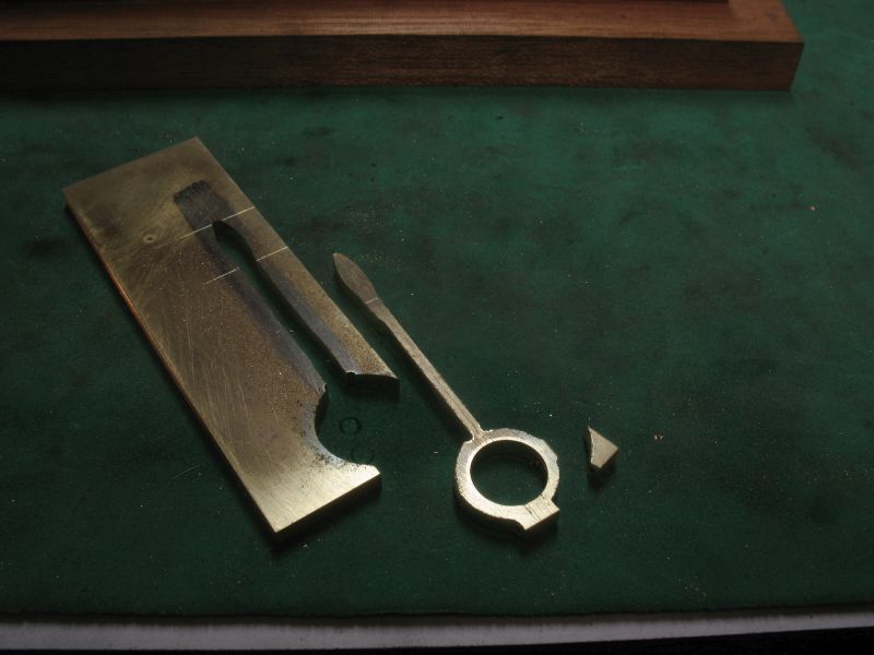
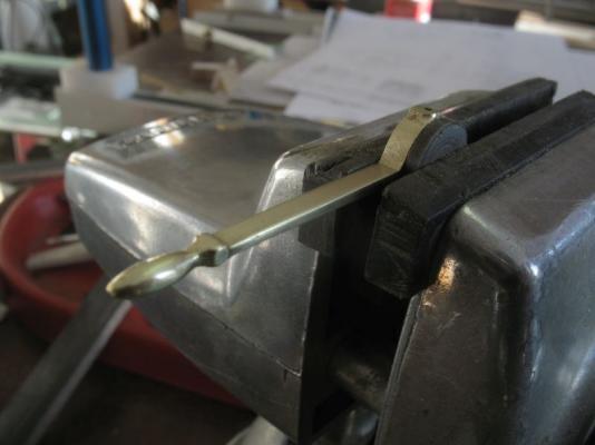
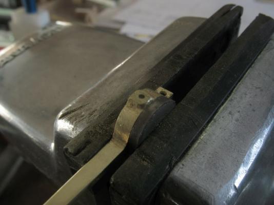
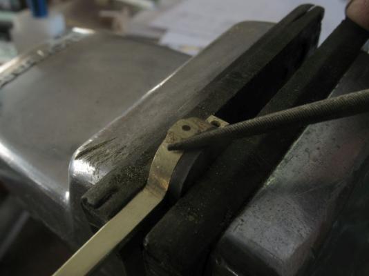
Thanks for the likes. I used a trick I employed when filing up connecting rods on my model steam locomotive, and that is to use a hardened button as a filing guide. The top of the handle ended up being hand filed I had originally intended to turn it in the lathe by holding the lever in the four jaw chuck, it caught and bent so after straightening it I used needle files sandpaper and steel wool to clean it up. Michael

-
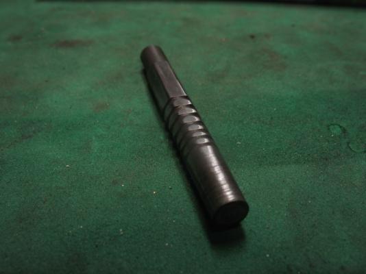
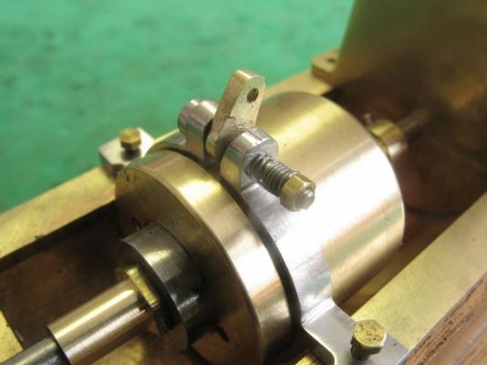
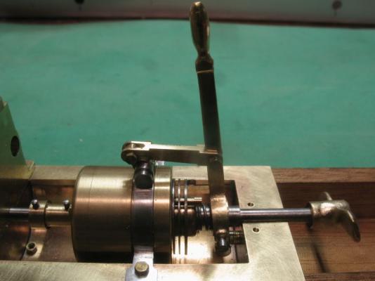
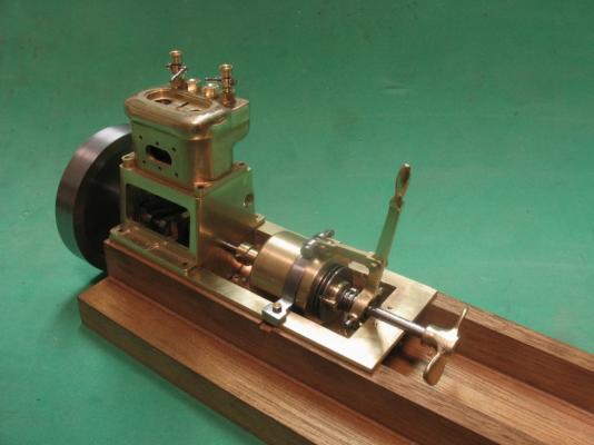
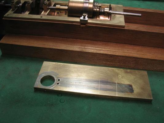
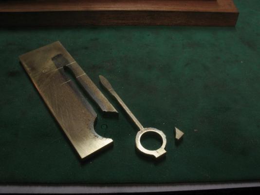
Greg, Mark, Carl and Mark thanks for your encouraging comments about my work, and again to all who have appreciated it quietly. Moving forward to the control of the clutch I have started to make the forward reverse lever. This lever will need to have some ability to be adjusted.To give just the right amount of pressure to the clutch spring. The geometry of the fulcrum points is critical. The strength of the coil spring is also one of the items that might need a few reworks to get right as well. The whole physics of springs and their construction is no doubt a science, but from my practical point of reference, a trial and error method will have to suffice. So I will see if it works. I rummaged through the scrap box until I found the right bit of brass to cut the lever out of. I used the vernier height gauge to lay out the shape, then pre-drilled all the holes while it was rectangular this makes it much easier to get them square to each other. the cutting was done with a fine blade in the jewelers saw. I have already started to file the surfaces to the final shape. The keeper rods are now set into the gearbox these were turned up from some free machining 1/8th inch hex stock, at first I left the heads as a hex bolt but they were too big and interfered with the pressure collar. so turned them into cheesehead screws. the spring was wound from some .020 music wire, I used the number drill series of drills as the arbor to find the correct size to finish up with a 3/16th internal bore the third attempt produced the correct diameter, it was a number 21 drill. The lower pivot point to which the lever connect to will be mounted on the back wall of the oil pan below the prop shaft, and will be able to be threaded forwards and backwards to give the adjustment. There will be a connecting link from the lever to the clamp on top of the clamp ring. Michael

-
Longboat by Rao A.L.G. - FINISHED
michael mott replied to Rao A.L.G.'s topic in - Build logs for subjects built 1751 - 1800
Rao, thanks for sharing your delightful model with us. I look forward to seeing your next build, I have a friend who is living in India at the moment and he occasionally send me pictures of the fleets of traditional boats in harbours. Your country has a rich legacy of building beautiful boats. Michael -
Looking good Jeff. Michael
-
Wow the figures really do put this little boat into perspective. Very nicely done Nils. michael
-
I could not have said it any better. Beautiful work Chuck
- 1,051 replies
-
- 4
-
-
- cheerful
- Syren Ship Model Company
- (and 1 more)
-
Row, thanks, we must have been posting at the same time, your comment is greatly appreciated. Michael
-
Bob, Druxey and Nils thank you all for your kind comments, they are very encouraging, makes all the re do's worth while. And not forgetting all the people who added a like. Nils, Not exactly, I have been making stuff though for a long time, and as a commercial model-builder and designer I had a lot of projects that gave me the opportunity to learn new skills. I have learned from my mistakes what works and what has not. I had good teachers at school, who encouraged a genuine curiosity for learning how to do things for myself. My woodwork teacher taught me how to sharpen tools. The first machine that I purchased was a Myford lathe back in 1971, I learn new things about how it works every day it seems. Michael
-
HMS Victory by willz
michael mott replied to willz's topic in - Build logs for subjects built 1751 - 1800
I take it that the split cannon is so that you can add them later so that they are not in the way while you complete other tasks. The stern details are very fine work. Michael -
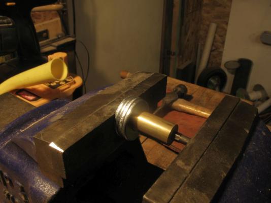
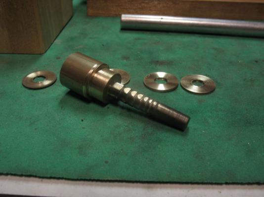
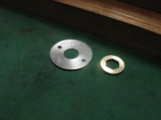
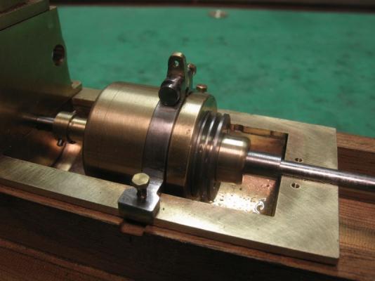
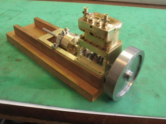
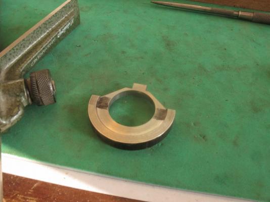
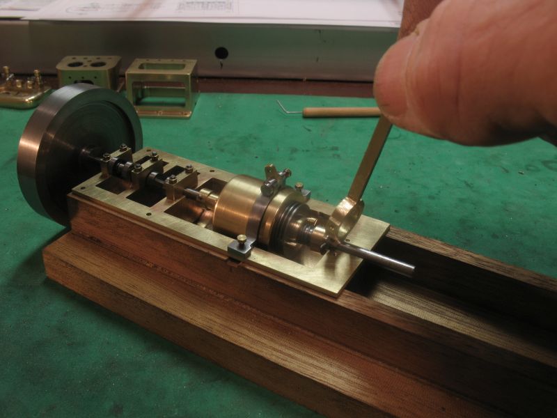
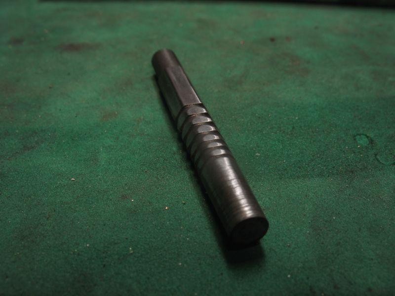
Ed, and Jack, thank you for your kind comments. and for all who added likes. I had to make a new band clamp because the tabs were not wide enough to bolt it to the pan. the new one was machined from a solid ring and then a lot of fiddling and filing to get it to spring just right. I also whipped up a flywheel because it is tough on my fingertips turning the 1/8th shaft all the time to test stuff. Today I worked on the clutch, it was a bit of a design build affair following the general principles, the gearbox and clutch will be underneath the cover so only the top of the linkage and the lever will need to be as accurate as possible to keep the appearance of the engine looking as the full size engine. I abandoned the cap screw hex and made a hex broach from a 3/16 allen key. first I heated it up and let it cool slowly to take the hardness out of it, then cut a taper on one end of the hex. Next I added the beveled slots to create the cutting faces. I ended up making a second one because I forgot to temper the first one after re hardening it, it cut the first hex through about a half inch length of brass stock, and then I tried a longer piece of brass and it shattered into three. Pushing the second one with the vice rather than using the hammer which is how I managed to wreck the first one. At the back end of the broach I reduced the diameter before it was hardened so that I could part off the disks one at a time, as the broach was forced through, each time the broach reached the end I put it back in the lathe parted off another disc Next I turned a few discs of mild steel off a blank that had been pre drilled for the keeper rods. the steel discs are 5/8 diameter and .020 thick the brass plates are 5/16 diameter and .040 thick. the steel discs will be fixed to the gearbox and rotate about the hex the hex will be pinned to the prop shaft and the brass plated will spin with the hex . Here they are test fitted for size, the wide brass collar is also keyed to the prop shaft and will be the pushing element to squeeze the plates together. Time for bed Michael