HOLIDAY DONATION DRIVE - SUPPORT MSW - DO YOUR PART TO KEEP THIS GREAT FORUM GOING! (Only 69 donations so far out of 49,000 members - Can we at least get 100? C'mon guys!)
×


michael mott
-
Posts
5,200 -
Joined
-
Last visited
Content Type
Profiles
Forums
Gallery
Events
Everything posted by michael mott
-
 beautiful job on the planking Toni, I also like the subtle contrast with the bamboo treenails. Michael
 -
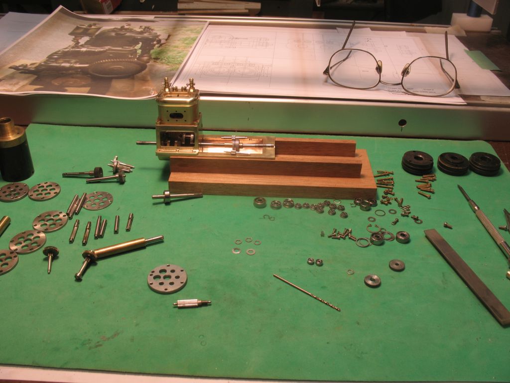
Ed and Row thanks for your kind comments. I had a bit of fun today I had some gear-heads from some pretty old servomotors full of very tiny gears and pinions all with micro ball races. I stripped these apart to see if there was anything that I could use to fabricate the revers mechanism with. With a bit of careful re-machining a couple of pinions and one of the main drive gears I think I will be able to pull this off, the progress so far. Cheating a bit I know bit machining gears this small is pushing my limits. I knew there was a reason for saving those gearheads these last 35 years. michael
-
Chuck you really do do a lovely job with the planking. Michael
- 1,051 replies
-
- 2
-

-
- cheerful
- Syren Ship Model Company
- (and 1 more)
-
Hi Jeff I have that book if you need to see it sooner that the inter library loan is getting it for you let me know. Michael
-
Looking great Denis....why do I get the feeling that a deadline is looomin' couldn't be anything to do with the fact that it is December now..... Michael
-
Mark, you are doing some very tricky woodwork there with lots of angles and curves, you are doing a fine job so don't be hard on yourself. It is looking great. Michael
-
Thanks for all the likes and nice remarks. I did finish up the head today. It was starting to bug me. I used needle files then 400 wet and dry 600 wet and dry 1200 wet and dry then red rouge on some swede side of a leather polishing stick. Michael
-
Longboat by Rao A.L.G. - FINISHED
michael mott replied to Rao A.L.G.'s topic in - Build logs for subjects built 1751 - 1800
Rao , the model looks great, very nice work, do you have a picture of the boat that inspired your model? Michael -
Mark, thanks I still keep thinking about the tiny stuff that gets put into so many of the ship builds. Michael
-
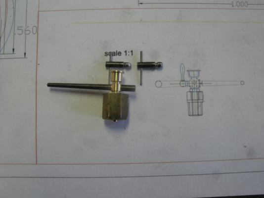
Steve the hole through the steel rotating part of the valve is .041 in diameter it is a number 59 drill the locating pin with the washer is also a taper pin and keeps the main part in place. they will work as real priming cups. Dan , yes it is me, and thanks for the compliment John, Thanks for the kind remark The handles on these valve are really no smaller than a large belay pin at .25" long they would be a foot at 1/48 scale and 18 inches at 1/64 I like the one on the right better than the one on the left so will replace the handle on the left one tomorrow. Some of the metalwork that I see being done on many of the ship build logs is much smaller that this engine. And thanks for the likes Michael
-
I just went to the page for the silver soldering tutorial to read Your article Russ and I found that the article for the silver soldering brought up the rope walk article. thinking I had pressed the wrong button i tried again and no the same switch , I tried the one above which is the one by Pat and the soldering article came up . So my question is .... is it my computer or is the index miss aligned? I am not complaining just noticed it. Michael
-
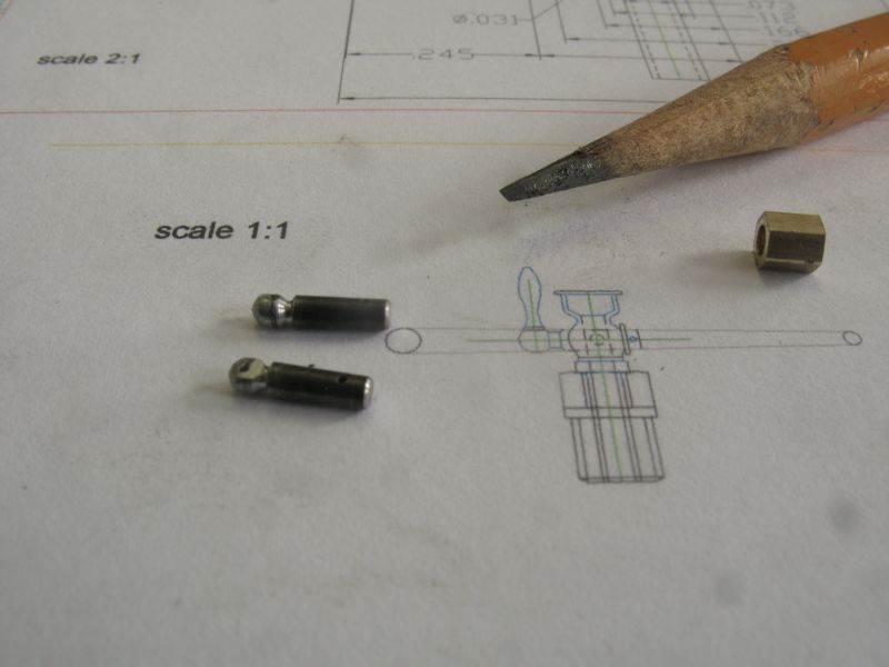
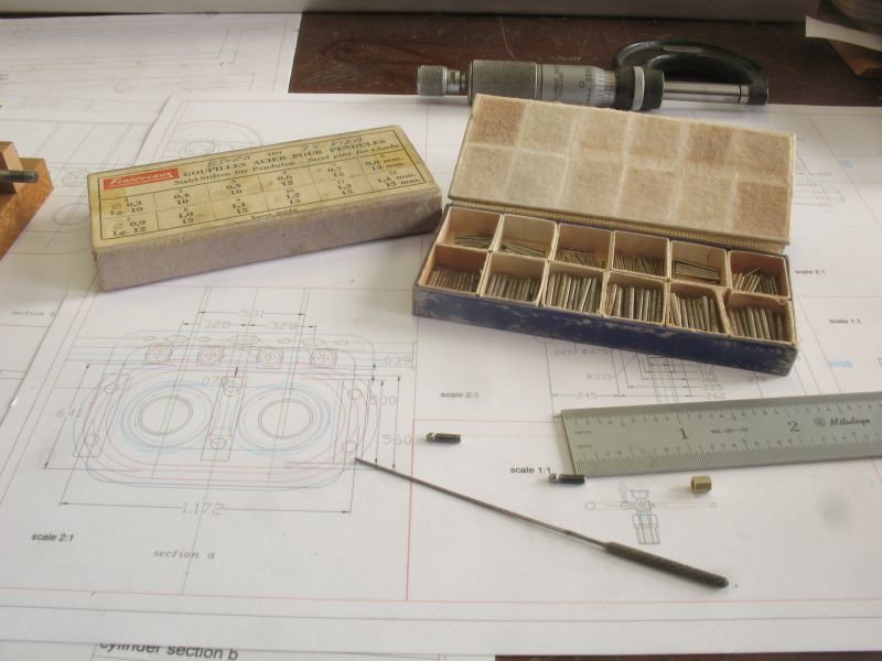
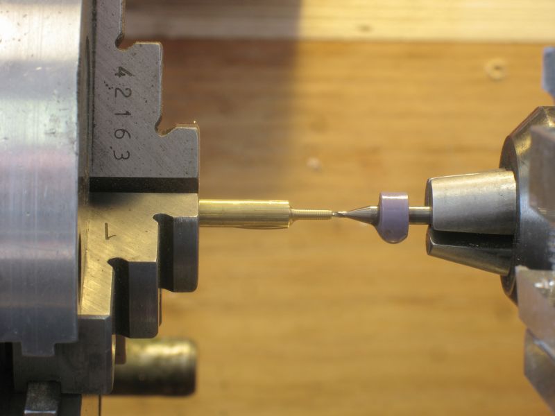
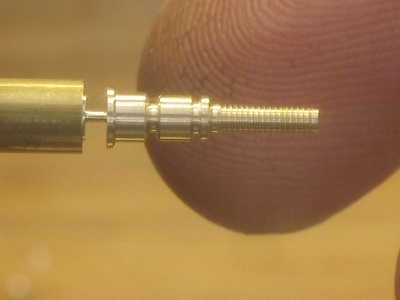
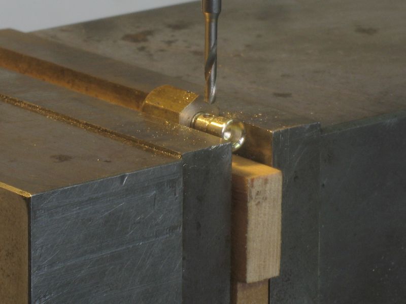
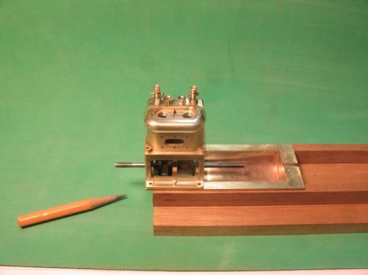
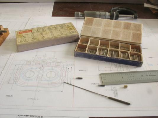
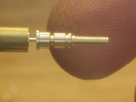
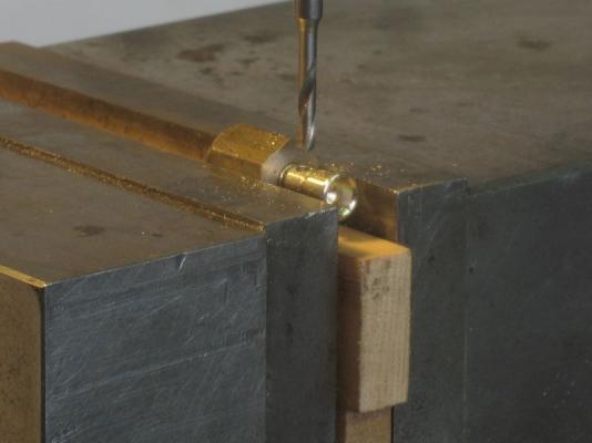
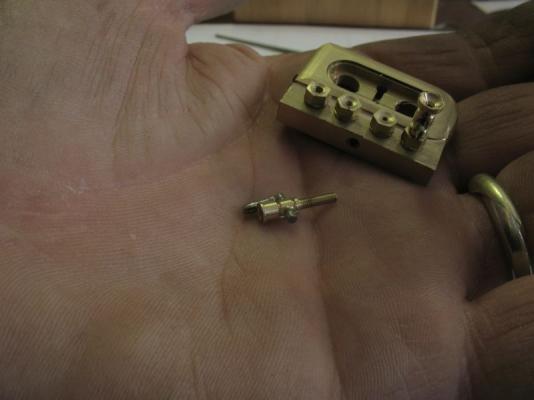
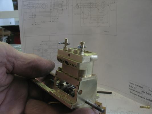
Thank you Ed, Tom, Carl, Bob and Row for your kind comments and to all those who liked the last few entries. I think I could make one of these small stop cocks now in my sleep. I have gone through a number of failures with silver soldering handles mainly because I was using the wrong approach to setting them up to solder. The following sequence shows most of the steps and elements in the stop cocks. ` First picture shows some 1 inch tapered clock pins cut to length prepared for soldering This one shows the box of tapered steel clock and watchmaking pins that that match the tapered broaches, I decided to use them instead of threading the rotating part and using springs and nuts. The hole through the centre was bored after the threading was done, with a number 59 drill, I used paint thinner as a lubricant, normally I do not use lubricant when machining brass but with these small diameters and threading it helps. A finger tip as requested behind the main body of the valve Drilling through the body for the steel tapered part. I found it helped to make up a couple of holding jigs with some hex brass rods. Using a full pin to test the depth of cut with the taper broach of the valve body In the palm of my hand for scale The new stopcock on the left with the old one on the right. I Like the shape of the longer handle better and it is also easier to turn, as I am sure they are in full size as well Another couple of overall comparison shots for scale I have all the parts now to make a pair of stop cocks like the new one, plus all of the steps figured out for soldering and final assembly. I think it is also time to finish shaping the top part of the head. Michael


-
Mark, I like the way that you are approaching this build. thinking about full size practice although obviously there are many differences with regard to mass and flexibility, I think that it gives one a more integrated feel for the model. Nice drawings, I like the colour and they remind me of the linen ones that I looked at at the Science Museum in London many years ago while researching the construction of the John Bull locomotive built in 1831 by Robert Stephenson. Michael
-
Karl yet again you raise the bar... What an incredible display of exemplary wood joinery. The photographs of the steps are treasures unto themselves. Michael
- 662 replies
-
- 1
-
-
- bonhomme richard
- frigate
- (and 1 more)
-
Alan she is looking very nice your patience with getting the hull cleaned up and reworked is all coming together now. Michael
-
Longboat by Rao A.L.G. - FINISHED
michael mott replied to Rao A.L.G.'s topic in - Build logs for subjects built 1751 - 1800
Rao, what a wonderful start to a good looking model by the looks of what you have already accomplished. You are following a long established custom form many parts of the world whereby boats are built by craftsmen who build boats without plans to do thwe work they needed to do. And so have you begun, keep up the great work and post more pictures when you can of your continuing progress. I can see why you would be very satisfied with your progress. Michael -
Ed looking at that third photograph with all the clamps, brings to mind how that area of the full size ship must have been the site of many shipwrights working together to accomplish such a complex part of the hull. Getting that shape right 72 times larger it would have also been very heavy to lift at fit, no doubt a lot of sweat was lost during that task. I continue to enjoy your attention to the details and the very fine workmanship. Michael
- 3,618 replies
-
- 1
-
-
- young america
- clipper
- (and 1 more)
-
Built another priming cup and stopcock, it is getting closer still needs some refining. michael
-
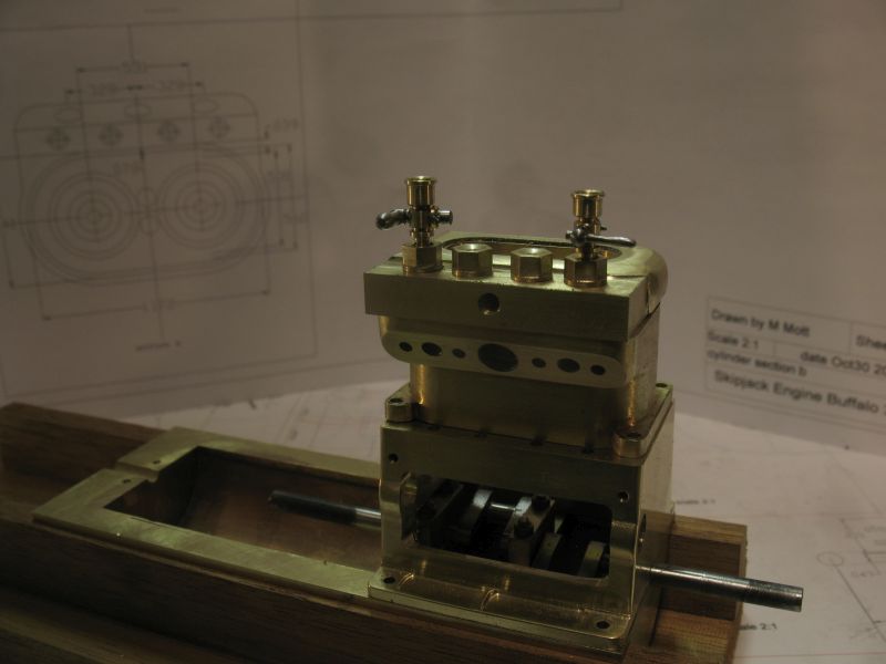
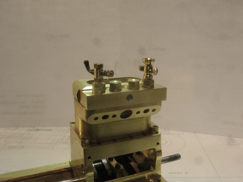
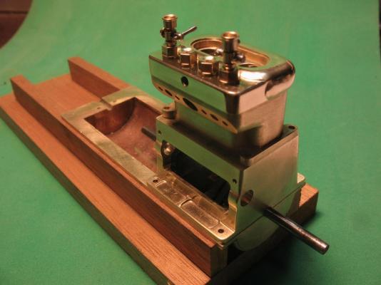
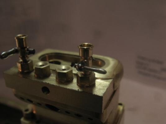
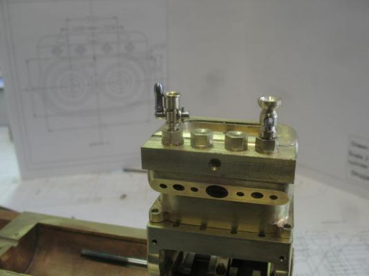
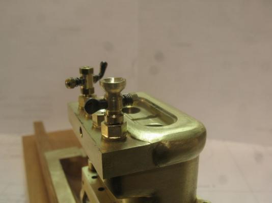
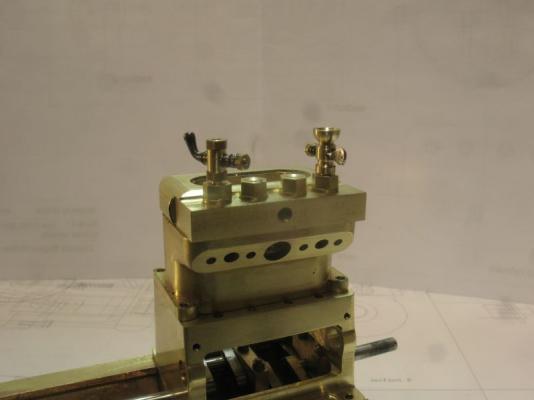
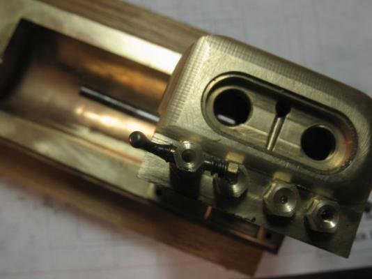
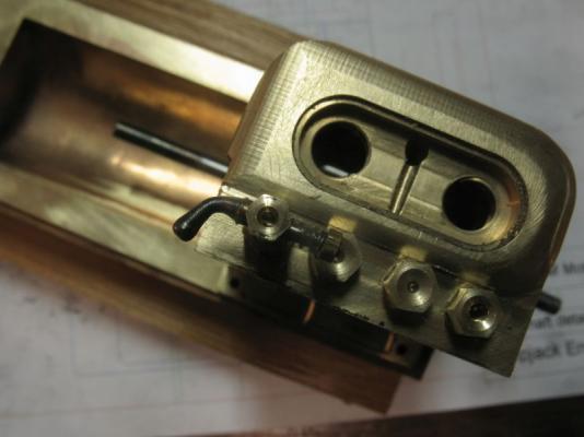
Jack, Row, Mark, Steve, Matt, Denis and Carl, thanks for the encouragement. Thanks to all for the likes. I took a break from the drive train today and fabricated the Valve caps these are there to allow the valves to be removed from the head because on the full size engine the head was a single casting. because of the small size of my model I have built the head in two parts. I haven't fully resolved how I will join them yet. The two outside caps which line up with the inlet ports are also set up as priming ports with a couple of little cups above the stop cocks that are threaded into them. like these on the top So I had a bit of fun having a go at making a stop cock to fit into the top. Looking down into the open valve. Now closed From the side The valve cap is threaded 8x36 into the head these were made from some 3/16th rod from Home Depot (nice hard brass) The valve body is machined up from some 1/8 hex stock, I have a fair bit of it left over from a commercial job 20 years ago (it was a special order locally and I had to buy 16 feet of it) it is also a nice free machining hard brass. The steel insert is a mystery steel (salvaged rods from a library card catalogue system filing cabinet) it seem to machine freely and is 1/8th in diameter. The threads on the valve body is 1x72 with a # 59 drill hole through the length. The cross hole was 1/16 then tapered with the largest clock making tapered broach. the steel was tapered to match on the lathe and threaded 0x80 for the retaining spring and nut. the handle end was shaped with needle files while still on the lathe then heated in a pin vice and bent with some flat pliers. Once the steel was shaped I set it into the brass body put it back into the lathe and drilled through the steel with the handle in the open position using the same #59 drill from the opposite end. It looks a bit crude and now that I know I can make one this small I will set up and make a pair that are a bit closer looking to the ones on the 1:1 engines Michael

-
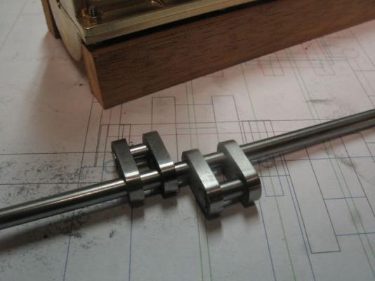
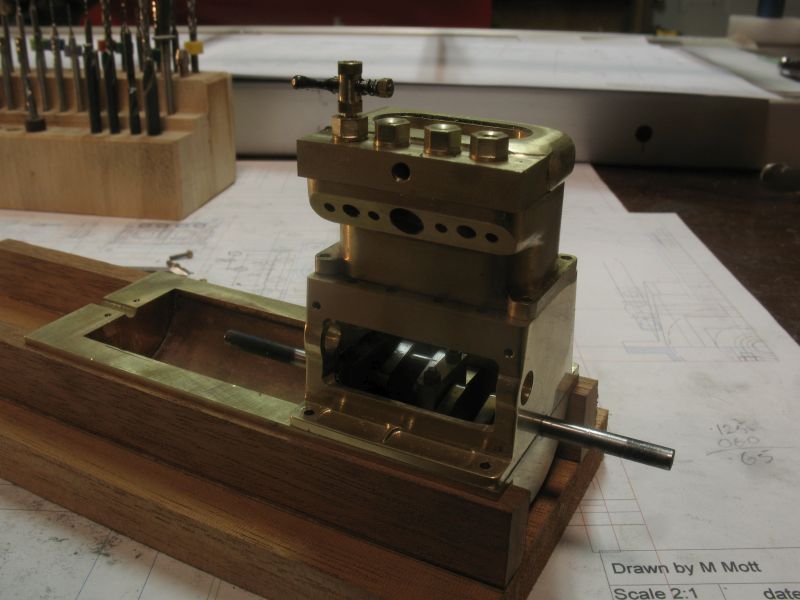
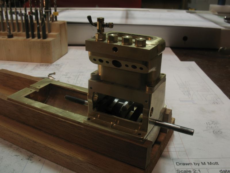
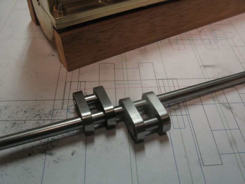
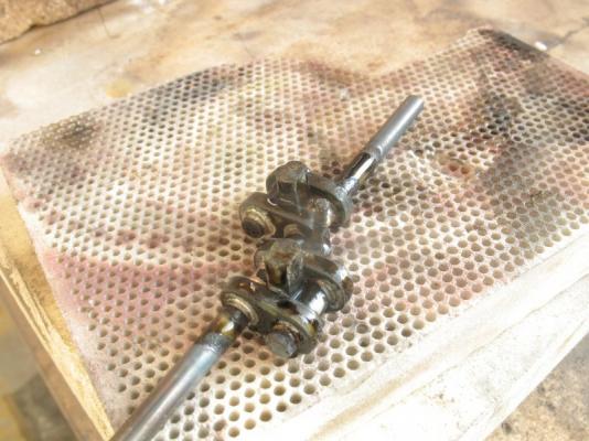
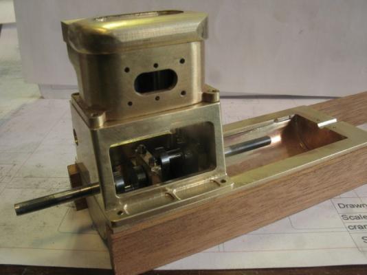
Steve, Carl thanks for your thoughts , and thanks you to all who added a like. Carl the real engine is actually quite a small one. Steve, My plan is to have it as a slow running engine am thinking that I will weight the flywheel with some lead in the outer area to give it more mass. My silver soldering was a great success..... not so with the clean up look at the upper right hand con rod bearing! Yup made the classic mistake of beginning to cut out the wrong piece I went ahead and cleaned it up because after letting the universe know what a silly move it was with a little colourful language, I wanted to see how the shaft fit and can also use it as a placeholder to test fit the con-rods and pistons knowing that I do have to build a new one. I was pleased that it did not warp and and my method of setting up the parts and pre-placing the solder by wrapping very fine strips around the shafts outside of the actual bearing surfaces worked very well. I turned up some sacrificial pins that were the same diameter as the spaces between the plates to hold things in line. after cleaning it up and placing it into the bearings the shaft spun nicely between my fingers. Next on to the con rods and Pistons. Michael

-
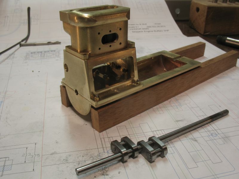
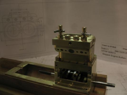
Row and Carl This is a picture looking inside the crankcase of the 3hp buffalo just like the one in Skipjack I have modeled my crankshaft after this one. Michael
-
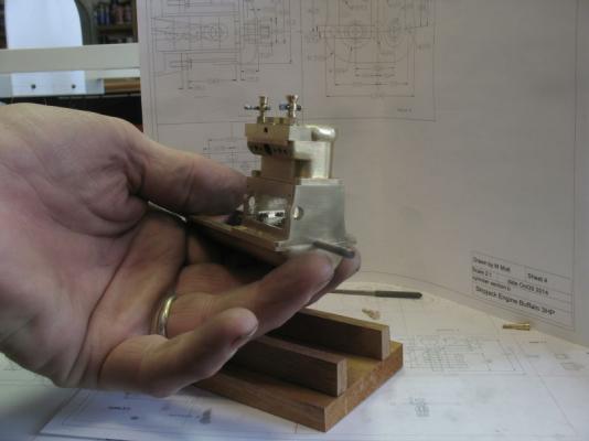
Steve interesting point regarding the polishing, I shall ponder that one. Carl, I am following the same shape as that on the original, and many of the small model engines that I have looked at have the same sort of configuration and do not seem to have vibration problems, that said I shall have to see what happens, it will be easy enough to build a different one if I need to. Michael
-
The battens really do make the lines more clear, she does look sweet. michael
-
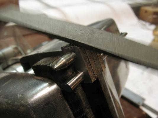
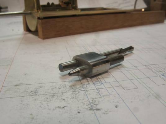
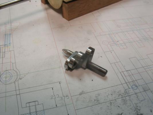
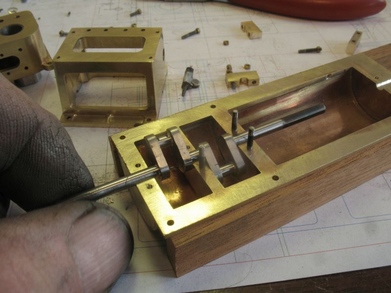
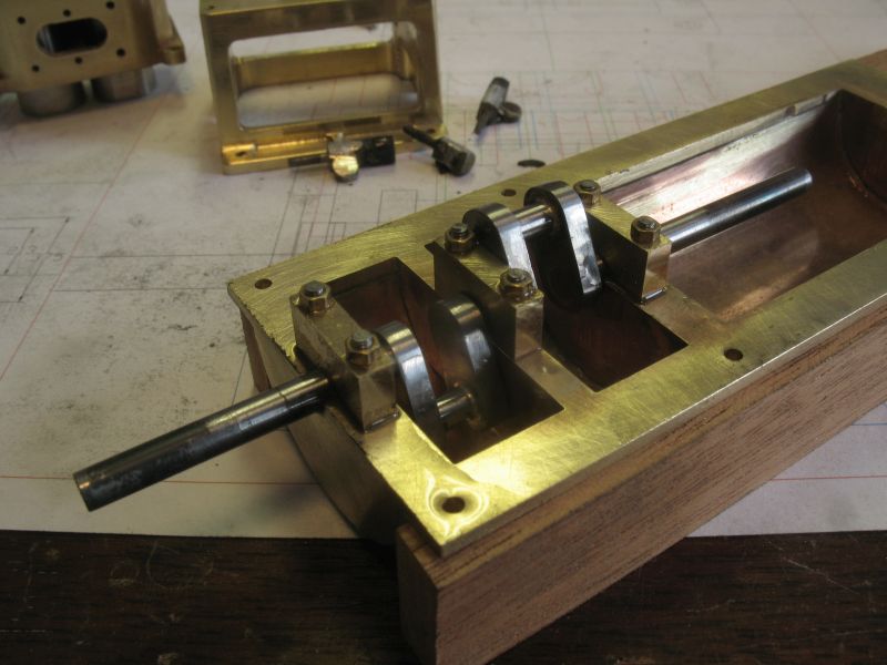
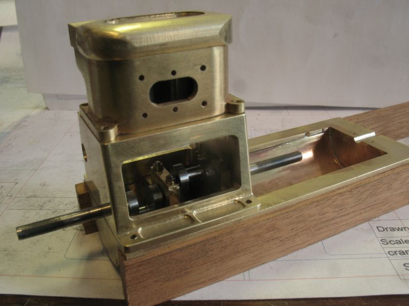
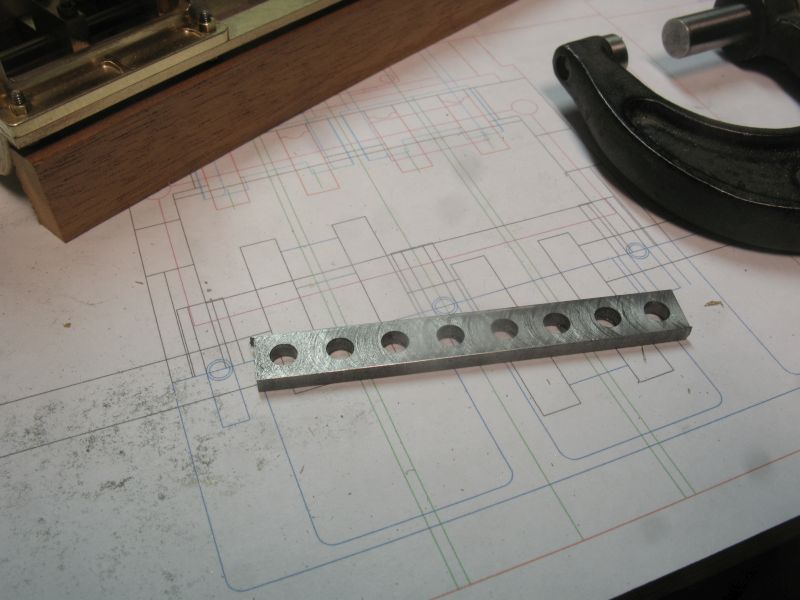
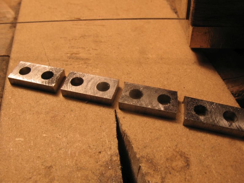
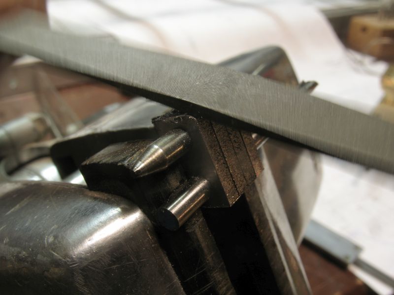
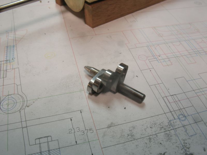
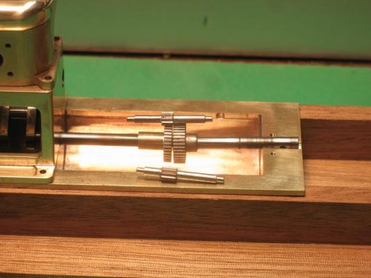
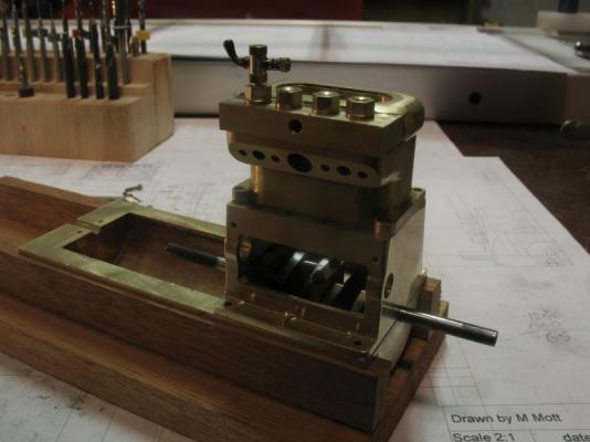
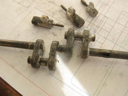
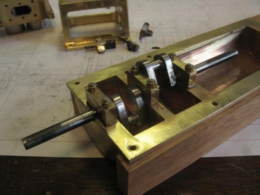
This afternoon after getting the shop warmed up a bit from 3 degrees to 13 degrees C I worked on the parts for the crankshaft. First I thinned down a piece of 1/8th gauge-plate to .094 then drilled and reamed 8 holes to 1/8th diameter. Next I cut the piece into the four plates for the sides of the con rod bearings part of the crankshaft, I used a new blade in the jewelers saw. A 1/8th set of dowels were slipped through the holes and the group were clamped in the vice and filed to shape. Then polished up with 400, 600, and 1200 wet and dry sandpaper., I like it when I can get a reflective surface, then I know it is pretty smooth. The sides of the plates will get polished Tuesday or Wednesday. Tomorrow is errand day in the big city. I turned up the .344" long 1/8 inch diameter shafts for the big ends of the con rods and did a dry assemble to see how the whole lot looks. I will silver solder the lot together then cut off the parts of the main shaft that are not needed. "The proof will be in the pudding" as they say, so crossing my fingers for a clean soldering job. Michael