HOLIDAY DONATION DRIVE - SUPPORT MSW - DO YOUR PART TO KEEP THIS GREAT FORUM GOING! (89 donations so far out of 49,000 members - C'mon guys!)
×


michael mott
-
Posts
5,200 -
Joined
-
Last visited
Content Type
Profiles
Forums
Gallery
Events
Everything posted by michael mott
-
 Sweet! I keep forgetting how small this boat is. Michael
- 120 replies
-
- 1
-

-
- mystic
- motor yacht
- (and 2 more)
-
Ed from the bow picture it is very evident that the time you took to get the frames accurate shows in the smooth lines of the top curves. Michael
- 3,618 replies
-
- 2
-
-
- young america
- clipper
- (and 1 more)
-
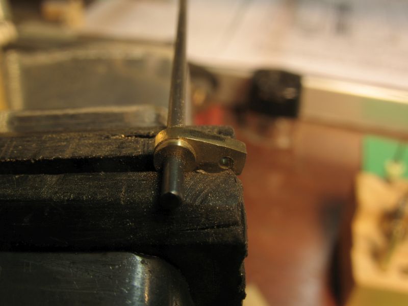
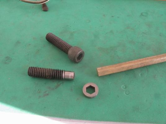
Steve the spline is for actuating the clamp so that the prop shaft is fixed to the casing or free to revolve have a look at this page the image shows the keys on the prop shaft because I cannot make these keys i used a slpine instead and with use the spine collar to clamp in the same way as the plates in the clutch. Michael
-
Very nice work on those screws Remco the rest of the rudder looks great as well. Michael
-
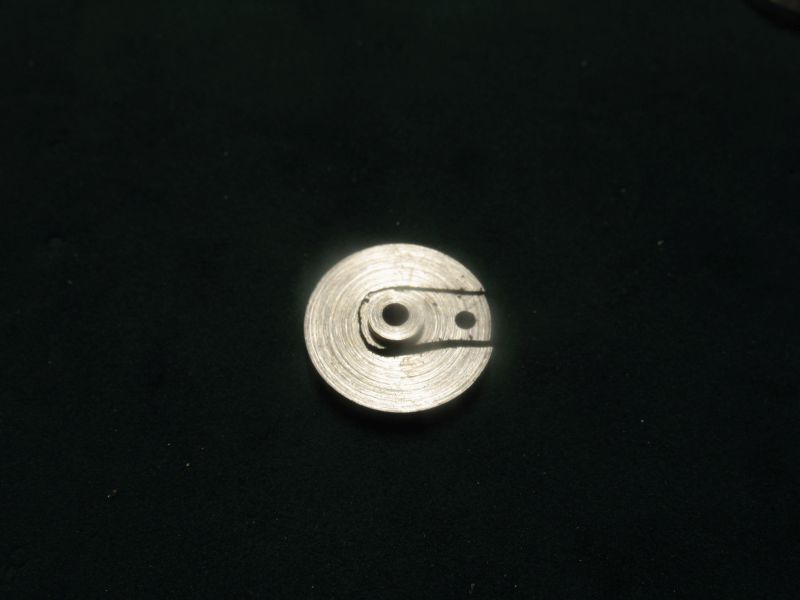
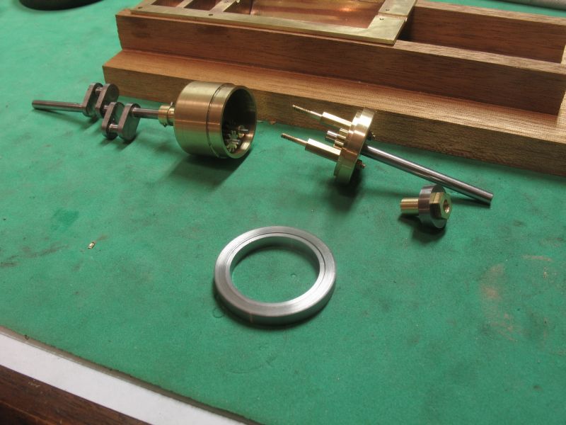
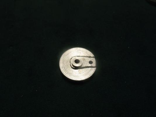
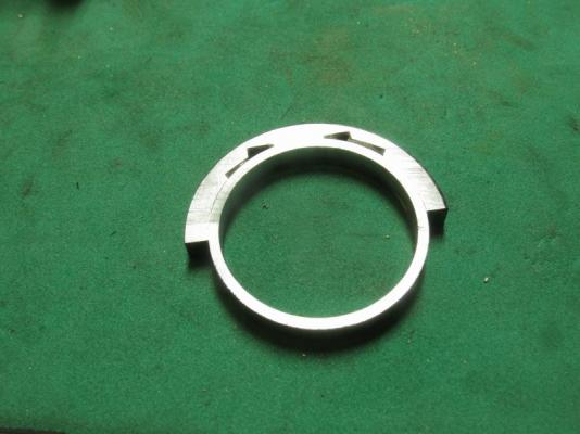
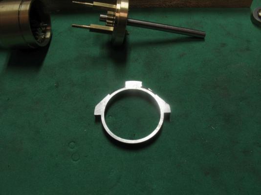
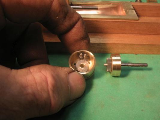
Remco, Steve, Joe, and Row thanks for your very kind remarks. Thanks to all who pressed the like button as well. I finished up the clamp ring today and made the actuating lever to open and close the ring, it is quite tiny but was manageable. in order to get the widths that I wanted quickly I spun up a disc on the lathe, bored out the centre hole on the lathe then stood up the rod with the disc still attached in the vice on the mill and offset the other hole .156" then took it back to the lathe and parted it off then used the jewelers saw to cut out the crank. Then cleaned it up with some files, then polished it up to a rouge finish and beveled the hub to create the cam. Here it is set in position with the spring loaded bolt in the open position the width of the flanges at the bolt are .290" And here with the lever in the closed position the width of the flange at the bolt is .250" locking the gearbox casing. This is how it works next the rear cam locking collar. Michael


-
Dan, that is an amazing amount of work in two weeks, not only that but it all looks really superb. Michael
-
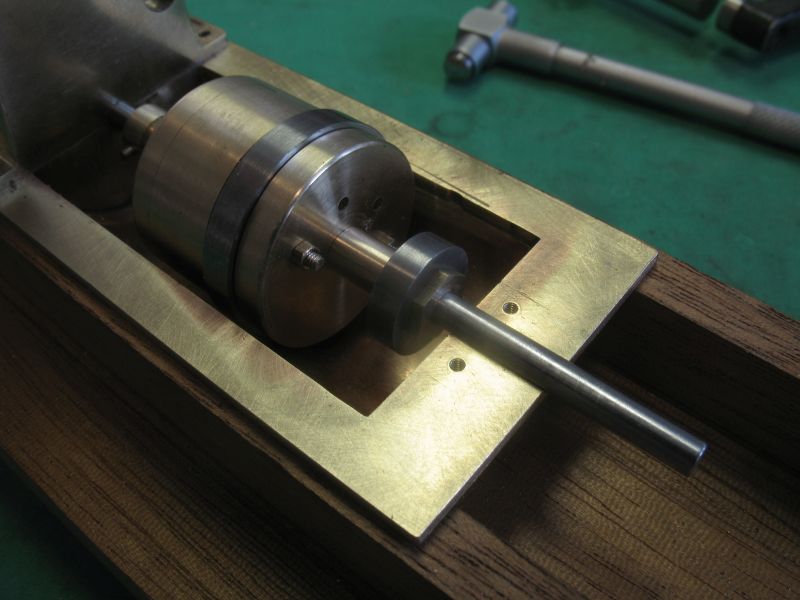
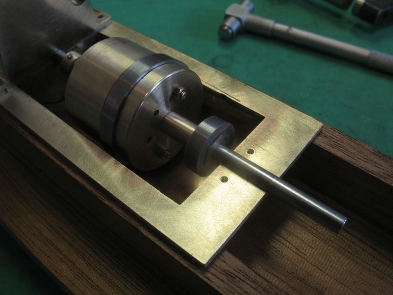
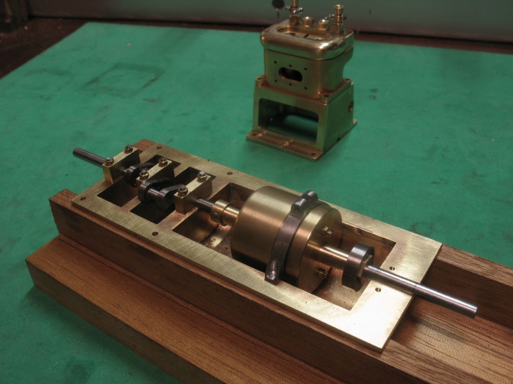
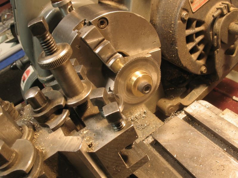
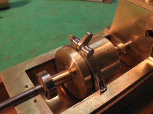
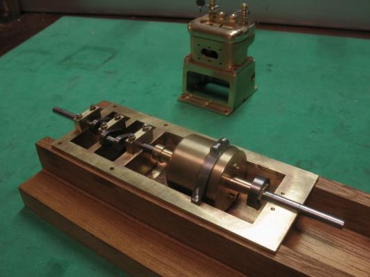
Thanks everyone for the comments and Likes. Its been a long couple of days working on the gearboxes, yes I ended up redoing the casing a couple of times over, I also opted to redo the inner stuff as well. Although the micro gears worked they were not as smooth as I wanted. I ended up using some 48DP "pinion wire" it is actually 10 tooth brass pinion, and is exactly 1/4 inch in diameter. this way I was able to go by the numbers and make the proper distances for the gears to mesh' Like this Video In order for the gearbox to be able to lock so that the prop rotates forward there is a clutch that is splined, I have been wracking my brains working at finding a way to make a small spline. This morning as I woke up it hit me. Yup the trusty old allen head cap screw has a negative hex to accept the hex key, I matched up a 5/16 cap screw with some 1/4 inch hex brass. the steel collar will revolve in the base of the forward/reverse lever and will move about 1/64 to clamp the prop shaft to the gearbox causing the forward motion. the hex part will be pinned to the prop shaft, and a loose clamping collar will be inserted between the hex collar and the casing of the gearbox, when the lever is pulled back the hex collar will move forward clamping the case and loose collar hence locking the case to the prop-shaft The revers is accomplished by clamping the gearbox inside a steel band which was made from some steel rings turned up and silver soldered together. As the gearbox is clamped the splined collar also releases the loose clamping collar allowing the gears inside to impart the reverse The rings were machined to shape using the mill and the lathe. When I cut the slot on the top of the band it automatically sprung to a smaller diameter which works in my favour because in order to open the band a wedge has to slide forward, this wedge is connected to the forward reverse lever. It is getting there. Michael


-
Pen Duick 1898 by Mfelinger - 1:20
michael mott replied to Mfelinger's topic in - Build logs for subjects built 1851 - 1900
Matija, well that certainly was dramatic, I completely understand your reason after seeing the way the grain looked up close. it does not matter how well laid the planking is if the wood has uneven grain structures, it looks odd. I look forward to the completion of the new planking.Nice work on the painting of the hull. Michael -
Steve that looks really sharp. I have to agree with you regarding doing fancy stuff to a beautiful piece of wood, By keeping it simple, the wood shows itself to its best advantage. Michael
-
Hi Nils, what a beautiful job of the clinker planking. I also have always admired the lines of clinker built hulls, the lines emphasize the shape of the hull so nicely. I like your analogy of the walnut shell also and you model is not much larger either. michael
-
Pen Duick 1898 by Mfelinger - 1:20
michael mott replied to Mfelinger's topic in - Build logs for subjects built 1851 - 1900
Beautiful work on the deck planking those curved planks into the king plank look so clean and precise. Michael -
Absolutely exquisite work on the planking chuck!! I am inspired to do a much better job next time I have to do planking. You should write a tutorial on Planking Michael
- 1,051 replies
-
- 2
-
-
- cheerful
- Syren Ship Model Company
- (and 1 more)
-
John very nice run on the planking I like the way they terminate at the stern rail. Michael
-
Pen Duick 1898 by Mfelinger - 1:20
michael mott replied to Mfelinger's topic in - Build logs for subjects built 1851 - 1900
Hi Matija I am going to be following along with your build, a great start so far. Michael -
As promised the short video of the gearbox in action. michael
-
Dan, thank you. Mark yes the drawing shows the lever, as the lever moves forward it causes the casing to be clamped. When the casing is stopped from revolving the drive gear rotates the first pinion which is in constant engagement with the second pinion (they are set in such a way that each pinion engages with only one gear), the second pinion drives the prop gear then in the opposite direction. when lever moves back towards the stern the casing is released from the band clamp and revolves, the pinions do not revolve inside the casing basically causing the drive and prop gear to be locked. I took a short video this evening and it will be ready to upload in the morning showing the basic process. Steve the above explanation should clarify the way it works. Thanks for all the likes. Michael
-
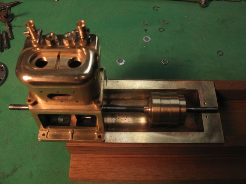
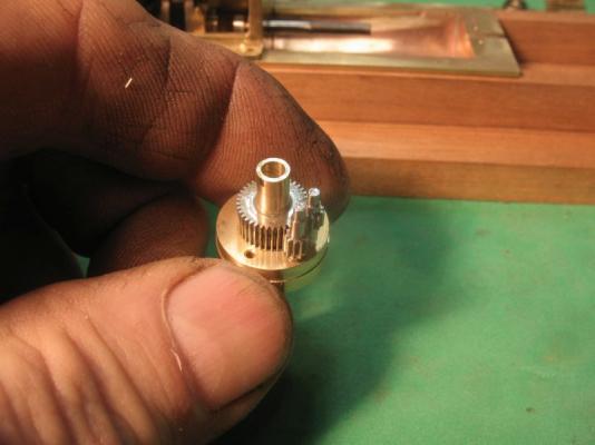
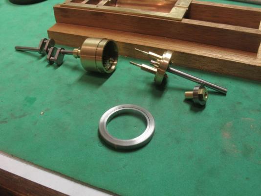
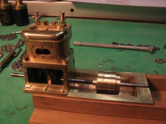
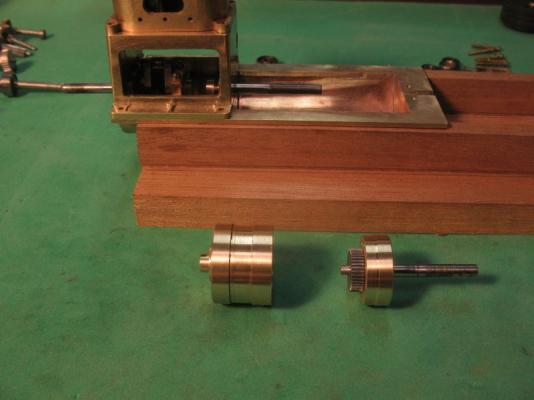
Thanks for the likes . I did make the casing today and fitted the gears inside. the gear for the prop through the end that will be shaped with the cone recess. The casing with the pinions and the drive gear which will be pinned to the crankshaft. The cone end with the pinions dropped in and the gears lined up for the casing to slip over. All dry assembled I also spotted three holes for some 0x80 bolts to ensure the casing and cone stay together and do not move relative to each other. I did check the reverse by rotating the prop to see that it actually worked to this stage. still a long way to go to get it all mounted and working in situ. It did work though so I am pleased about that. Michael


-
Wonderful work with the carving Gaetan, your work is amazing. Michael
-
My own thoughts are that the black looks better than the very light colour. Michael.
-
Shucks Jack, now you have spilled the beans Jude was trying to keep this present a secret Michael
-
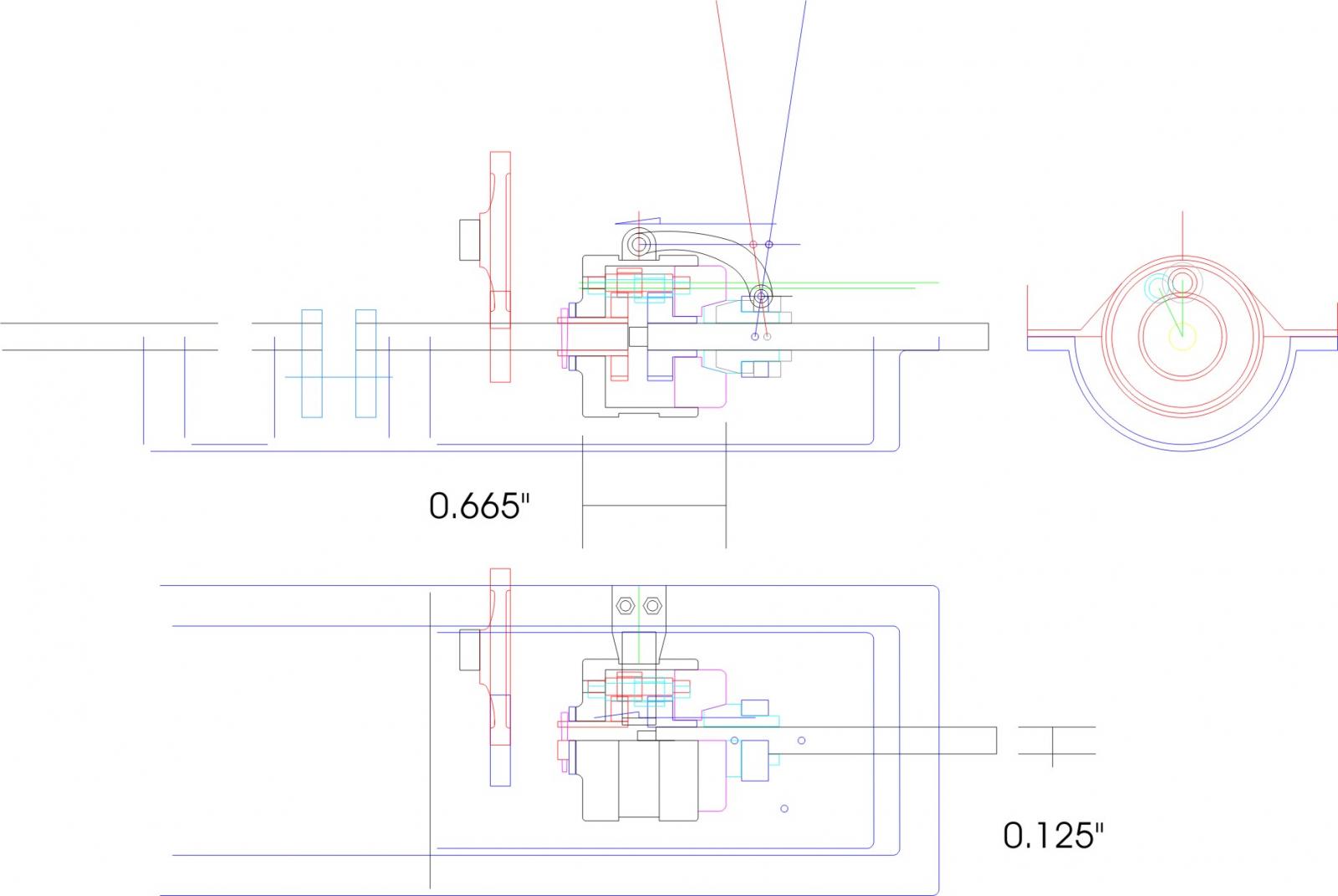
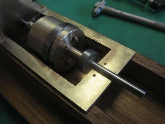
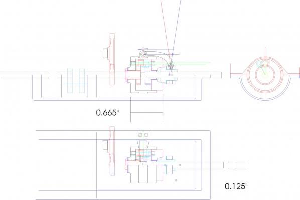
Mark, Steve, Ed, and Denis thanks for your comments, and for all the likes. Denis the picture shows the few parts that I am using just placed to get a sense of if they would work. I have since been working on the design of the reverse mechanism, for reasons of scale practicality, and to maintain some sanity I am working with the two pinions and the two spur gears and drawing a gearbox that will work. The entire gearbox is covered with a protective shield (no doubt to prevent feet or clothing from getting snagged) on the full sized boat. So I am working with some drawings from the day showing how these gearboxes worked, and fitting in the gears that I have to make the mechanism work. The originals used a series of clutch plates and the forward /reverse lever either caused the outer casing to be rigid hence letting the internal planetary gearing to impart a revers motion to the prop shaft, or they clamped the prop shaft and casing together causing the whole body to revolve giving a forward motion. The vertical position of the lever caused a neutral position for the prop. Here is a drawing of the progress of this design so far, I have re-machined the pinions already the shafts were pretty hard and it was nerve wracking to say the least. today I am going to make the outer casing this will be brass. this will allow the gears to seat in brass giving a quasi bearing, similar to an old clock where the gears are steel and the clock plates brass. revers gearbox.pdf As I say this is a drawing in progress and is a bit of a design build as far as the internals are concerned my goal is to have the external appearance to match the picture of the engine in the real boat. Michael
-
Ed you make all this complex joinery and planking look easy, but we all know it is not. great work. Michael
- 3,618 replies
-
- 2
-
-
- young america
- clipper
- (and 1 more)
-
Johan very nice details, Thank you for the pictures of the water inlet filters I have filed that away for reference for my own model I will need real working filters and that cap will cover the mesh perfectly. Michael