michael mott
-
Posts
5,200 -
Joined
-
Last visited
Content Type
Profiles
Forums
Gallery
Events
Everything posted by michael mott
-
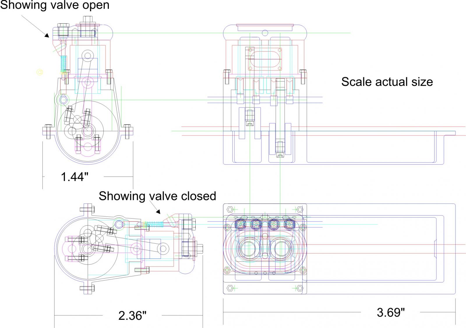
 Omega, here is a drawing showing the cross section of the engine and the camshaft with the valve in the open and closed positions. valve train.pdf Bob thanks for the compliment, one of the difficulties of working with the small sizes is that when drawing they are as big as the screen and it is a constant effort to remember the real size as I am drawing. when an area looks about right and then I realize that the dimension might be only 1/64th I have to do some rethinking. Michael
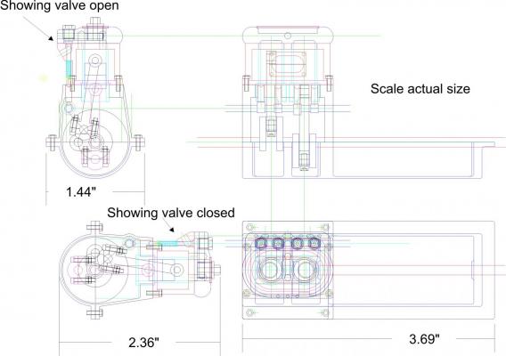
-
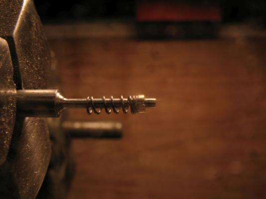
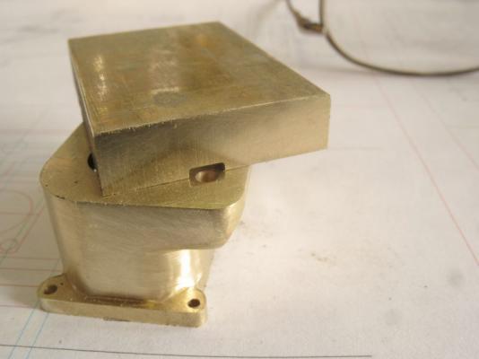
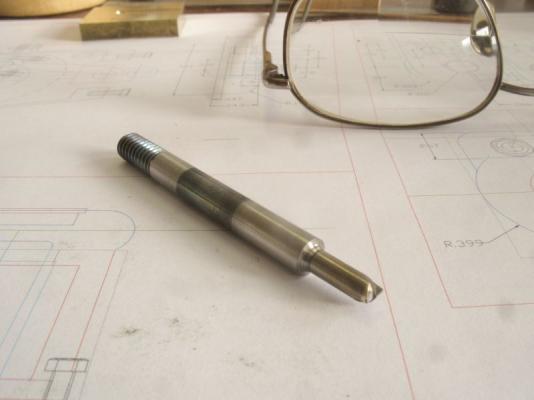
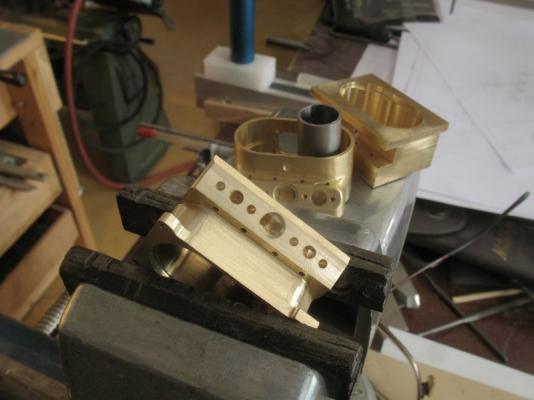
After doing a few experiments with the valve stem springs and keeper, I have increased the diameter of the valve-stem to .060" inches leaving the narrow section for the keeper at .046" This was one of the early tests using the .046 stem the spring is .078 in diameter and the wire is .011. the keeper was a bit fiddly. I can safely increase the stem diameter and still maintain the .078 diameter springs the length of the springs are ..259" presently I am learning how to wind them so that there is a double coil at each end with the wider spaced turns in between. I have found that it is better to make them this way rather than winding a length then stretching it out to form the compression spring. The crank case is progressing well at this time also. there is a fair bit of hand filing to finish up the corners because I do not have the requisite end mills to do all this work on the milling machine. this next picture shows the flats on the sides of the liners slipped through the top of the upper part of the crankcase. that's it for now. Michael

-
David the Kufu boat is one of those that I have thought about for a long time, it is my favourite in Landstrom's "Book of the Pharaohs" also the book "The boat Beneath the Pyramid" by Nancy Jenkins and John Ross. both of which i have spent many hours reading. Michael
-
Steve the valve stems are .046" it is the springs that I will be concentrating on first. Michael
-
Nice work on the balusters Dan. Michael
-
Beautiful work on the rigging Danny. Michael
-
That second to last shot really shows her off nicely. Michael
- 120 replies
-
- 1
-

-
- mystic
- motor yacht
- (and 2 more)
-
Nice to see her finished Bob she does look grand. Michael
-
Good afternoon Ed, The idea of making the piston rings is appealing. There are a number of threads on the model engine site that have basic tutorials on making them. some folk seem to have no trouble and others find it difficult. Fine grained cast iron is the key from what I can gather and annealing the rings is the tricky bit. I shall have to look into the sources of the iron locally. The engine is four cycle so the valve train will be an important element to get correct. I am going to use a Hall effect transistor ignition system. Thank to all for the likes Michael
-
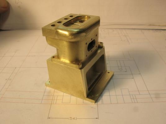
Si, thanks for the kind words, Denis I like your new avatar, The song "Imagine" is my favourite song of the last century. I started working on the crankcase it is cut from a block of brass that a friend gave me, it was given to him by somebody who melted down a bunch of odd bits of brass. it is hard and fine grained. The block was about 5 inches long and 3 wide and about 1 3/8 thick looked like it was cast in a mini bread pan. The brass cut nicely in the cut off saw. This is the progress on the flats that will slot unto the crankcase hole. this will ensure that the sleeves remain seated, this is because I am not familiar with the differential expansion of the brass and stainless when the engine warms up. I doubt that there will be any problems so this is just to keep my mind at ease. Michael

-
Carl that is an interesting question? and I am unable to give you a definitive number, I used the milling machine vice to push them in and in order to ensure that they stay in I am adding a couple of flats on the outside of both so that they will lock against the surface of the crankcase. I will post a pic later which will make it more clear. as far as the diameters go it was a case of "go" "no go" The no go was the diameter that was the push fit probably .00075" difference. Steve, thanks yes I have been shaping metal for a long time. Got my "O" level metalwork two years early, thanks to a couple of very special teachers at my school. Our drafting teacher was from Napier Aero Engines. His Uncle was a model ship builder, And my woodwork teacher taught my own father. My metalwork teacher was very encouraging, and tough as nails, he did volunteer work at Wormwood Scrubbs (penitentiary) Thanks to all who added likes. Michael
-
Beautiful workmanship Ed, I now know how you manage to get so much accomplished, I see that in picture six you are still working at break neck speed even as the photograph is being taken;>) Michael
- 3,618 replies
-
- 2
-
-
- young america
- clipper
- (and 1 more)
-
Denis it is fun following along with your builds. Michael
-
Thanks everyone for stopping by and for all the likes, it is very motivating. I have been out of the shop since Thursday evening I went to Calgary to visit my grandsons and play "electric trains" Today I did a little more work on the water jacket, I finished shaping the insert for the bottom of the jacket sweated it in place and bored the holes for the sleeves. Also did some shaping of the top part of the cylinders. after making a second milling cutter for the curves on the top. The stainless sleeves are reamed and fitted, they are a press fit. Michael


-
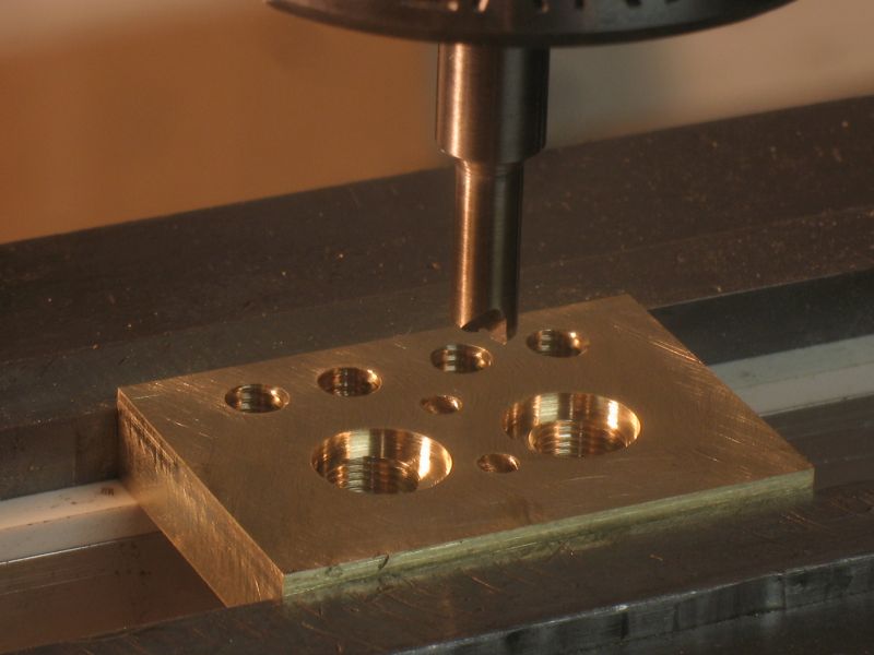
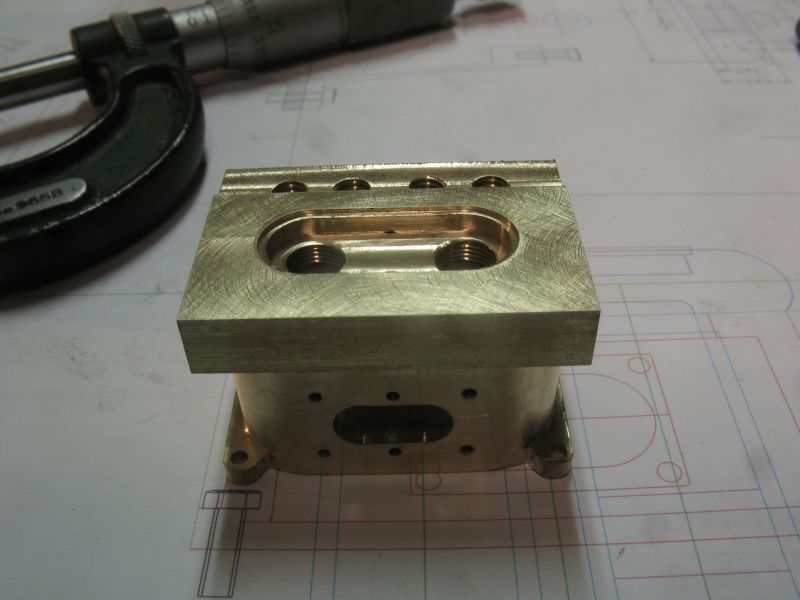
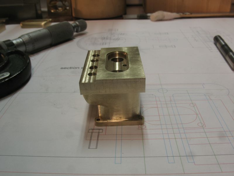
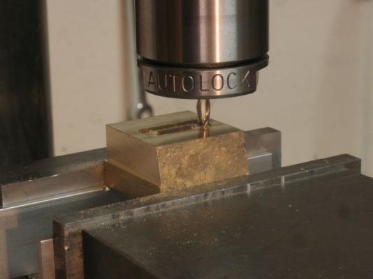
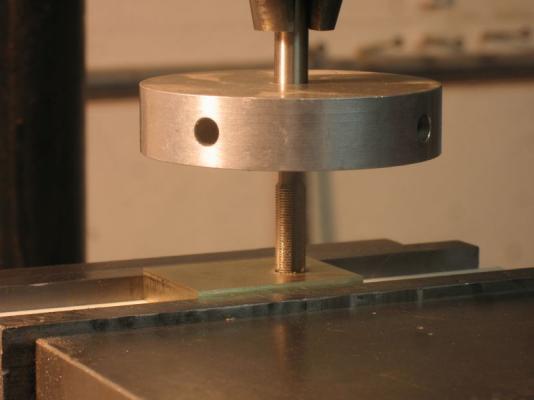
Thanks for all the likes, and to Row ,Mark, Druxey, and Andy thank you for your kind remarks they are very encouraging. Began working on the new head part today but first I needed to make a couple of tools to help with some of the tasks. first one was an end mill that was .155 in diameter and with a .015 radius at the cutting edge this was to ensure that the combustion cavity had a bit of a cove rather than a sharp corner. a test cut The second one was to make a collar for the 6 x .05mm tap so that I could tap in line accurately without taking the drill chuck out. It is just a disk of 1/2 inch aluminum with a couple of grub screws at right angles I ground a couple of 1/16th flats at the threaded end of the tap then I could use the drill chuck as the guide by releasing the tap from finger tight this way the drilled hole and the tapping are able to be accomplished without moving the work. Then a lot of fiddly settings to shape the cavities. next comes a lot of filing to finalize the shape. Michael


-
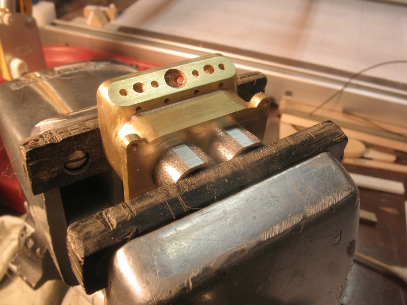
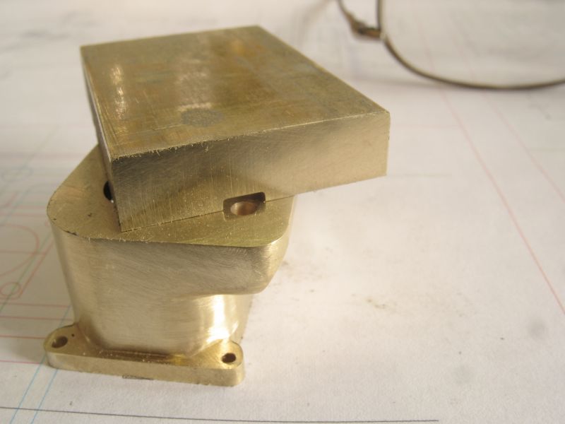
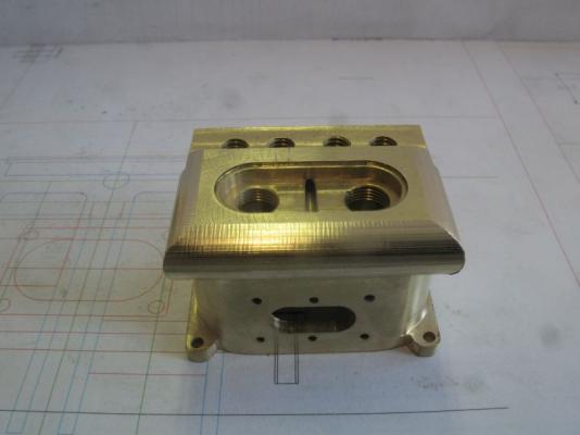
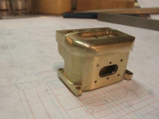
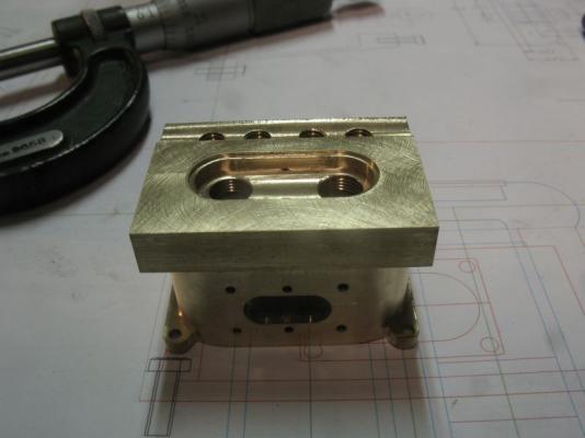
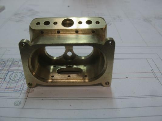
TAKE... ME... TO... YOUR... LEADER Sorry I couldn't resist, I just showed this to Jude and she said hey it looks like a face then in a robotic voice said "take me to your leader" I laughed out loud. Just a bit more fetling and then I can move on to the next piece. I need to add a couple of relive grooves so that the jacket clears the valve springs, I will use an .093" end mill. lay the block on the top face and centre the end mill over the valve guide holes and just take a whisker off down to the holes. Bob thanks for your very kind comment. Thanks also for all the likes. Michael
-
Remco the metalwork is superb, however I am still getting my head around the stunning joinery on the rudder sections. Nice way to solder the small elements on the corners. A Master Craftsman and Artist you are Sir. Michael
- 1,215 replies
-
- 3
-
-
- sloop
- kingfisher
- (and 1 more)
-
Just catching up Walter, wow I did not realize that you were going to double plank the hull, nice work on the retro fit so far, and as you say the extra flotation always helps. Michael
-
Good to see you back at work on the QA nice details, following your thoughts on all the gun positioning and working , I cannot imagine what a horror story it must have been for the people involved with the work of using them in the heat of battle. I hope for a more peaceful future. Michael
-
I think that you are absolutely right, and all the unfinished work out there is when this bond is broken. Stunning work on the cabin, It is hard getting my head around how small this little gem is. Michael
- 120 replies
-
- 3
-
-
- mystic
- motor yacht
- (and 2 more)
-
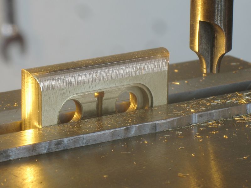
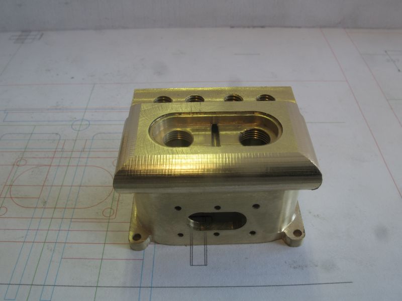
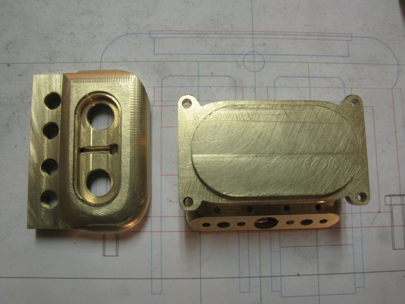
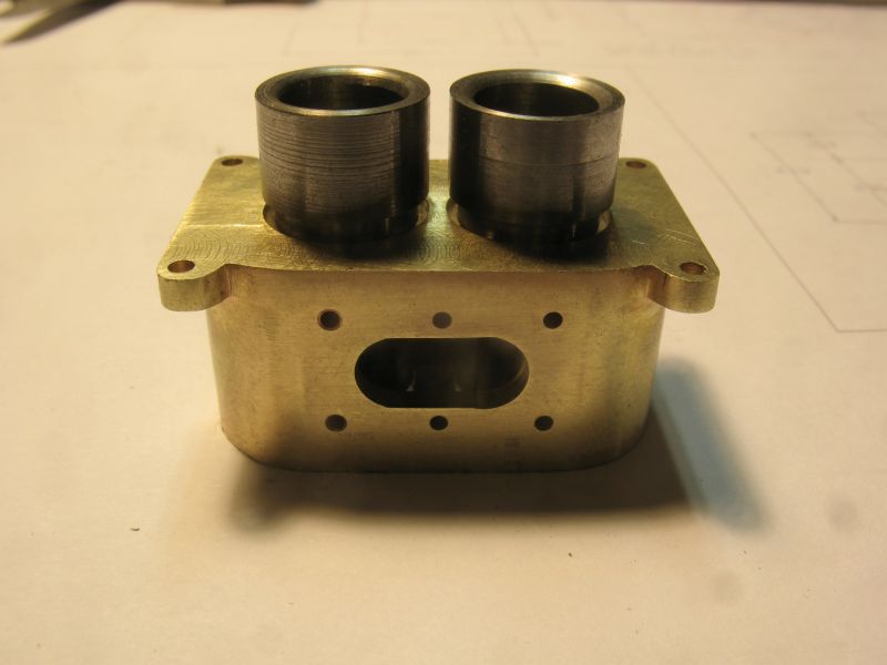
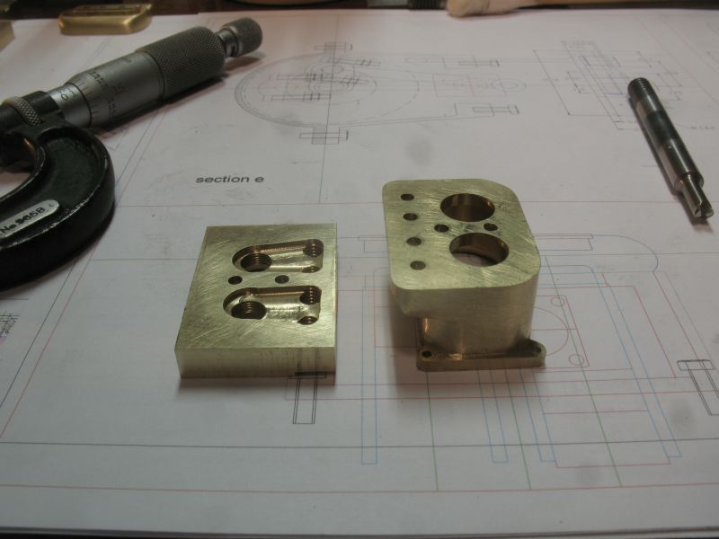
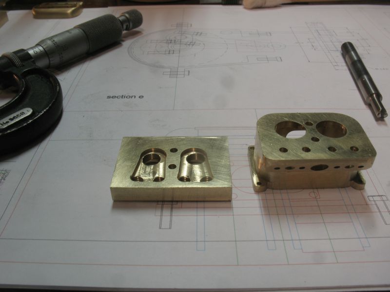
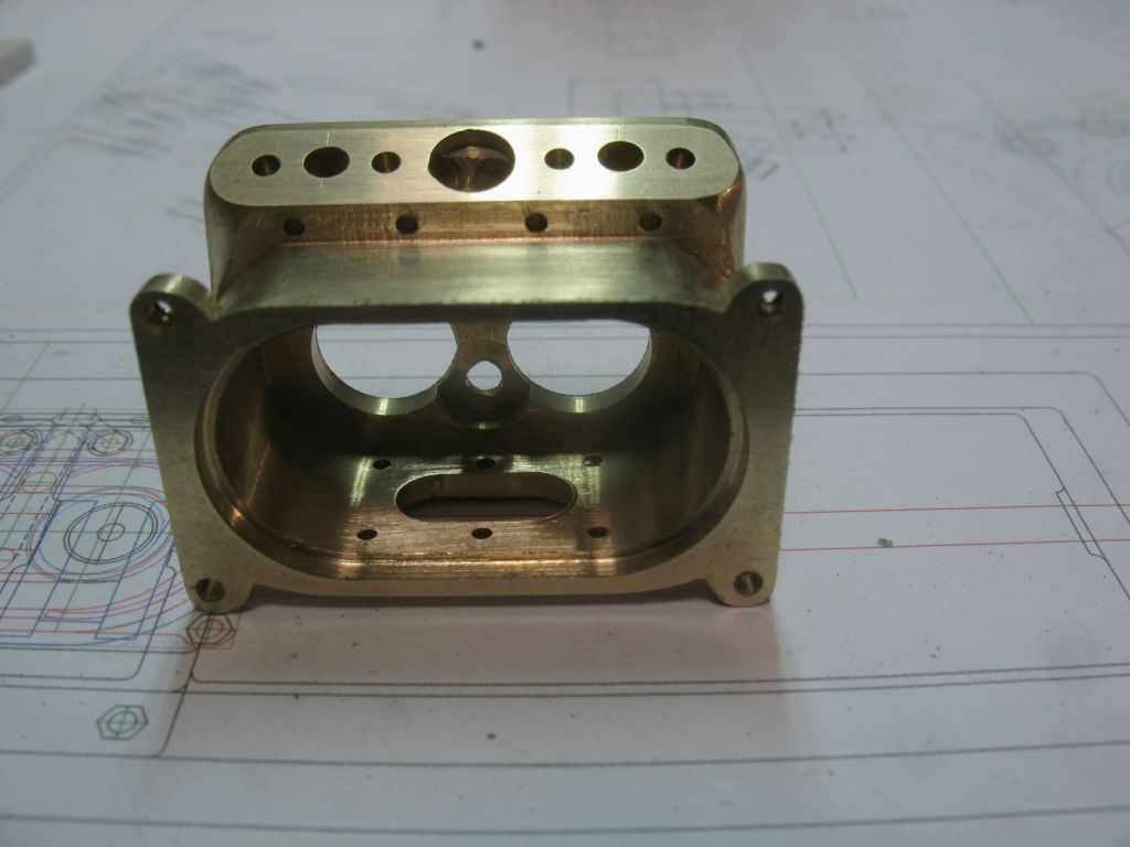
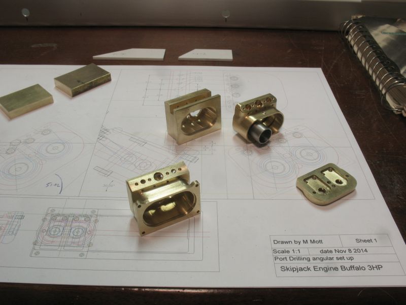
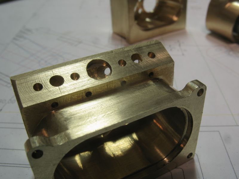
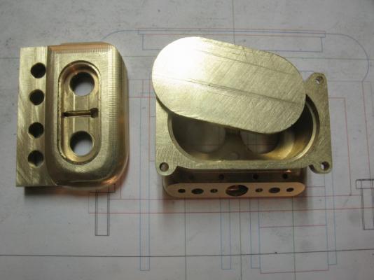
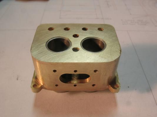
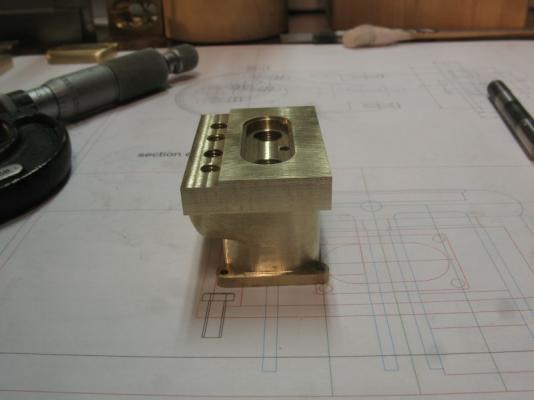
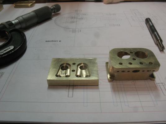
Denis ,Row, Dan, Carl, thanks for looking in and for the kind words. I am beginning to wonder about this engine business. The three cylinder blocks so far! The one in the middle was the first one I was getting more dissatisfied by the hour, because the little break through into the water jacket area was nagging at me all the time. It was actually the second of the things that was bugging me and the top part had its own error I realized the oval water area was too long. also I decided that the bottom mounting lugs needed to be an integral part instead of part of a plate that was going to be fitted to the bottom somehow? So I started over and was merrily milling down into the water jacket area when saw the cutter making it way down the outside of the jacket....... yup I set the cuts on the mill from the wrong side of the block after working the outside dimensions. you can see the clean little slot on the one in the back, right down the middle. The one in the front is version number three, according to folk lore it should be lucky. The most tricky part was drilling the inlet and exhaust holes (still a bit gun-shy after the first mistake) I had to set the block up with a compound angle, for each hole the inlet ones on the outside and the exhaust ones in the middle. Now the hand work filing the surface shapes is under way. I also increased the size of the valve heads to .125 from .093 inches. The bore of the cylinders is reduced to 5/16 from 3/8ths in order to get more space for water circulation. Carl in answer to your question why brass instead of iron, it is because brass is easier to work and I have the material. I have noticed that some of the engines on the engine website are brass and they seem to run fine as long as there is a steel or iron liner and an aluminum piston. this is the route that I am following. Michael


-
Mark, Oh this is going to be fun to follow. looking forward to seeing the wood chips fly. I have the issue that you mention and it is a boat that I have also admired for its sea worthiness michael
-
Hi Mark also catching up yes I have to agree with Yoda regarding the "do" "not do". regardless how many times we work on a particular item or element of one we are doing. Your model of Licorne is showing what a great job you are doing in transforming the raw materials of nature into a beautiful example of a ship that was built centuries before you began your work, which makes it even more challenging because you cannot nip down and take a look at the original to verify some detail. One day in the future you will look back and reminisce about how you accomplished this or that part of the build as yo look at the completed work. Michael
-
My Goodness Omega you need to take the blue protective wrapping off those engines or the melting plastic will smell up the whole cabin Lovely work as usual, Now those are tiny details. Michael
- 120 replies
-
- 1
-
-
- mystic
- motor yacht
- (and 2 more)