


mbp521
-
Posts
948 -
Joined
-
Last visited
Content Type
Profiles
Forums
Gallery
Events
Posts posted by mbp521
-
-
Eric,
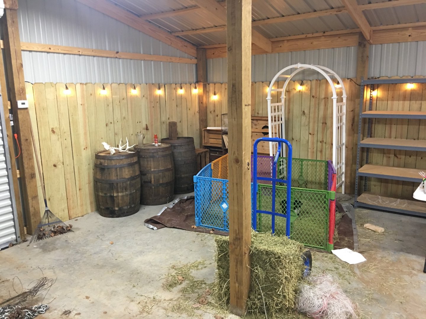
it’s all good. I’m actually surprised she let me stay put for as long as she did. But, like I said, I have my corner of the barn picked out and just need to get off my tookus and get my room built out. Should only take a couple of months to get done.
Future shipyard spot.
-Brian
- cog, GrandpaPhil, Altduck and 2 others
-
 5
5
-
Good evening everyone,
I am finally back with an update. The holidays season seems to cut down significantly on the build time. That and unexpected work trips have slowed mine down to a crawl. Unfortunately this may be the last update for a while. The admiral was gracious enough to lend me part of her guest bedroom to use as my shipyard, but now she has put her foot down that I get out, so I have to pack it up and move it to the barn. This is not a bad thing though, I will have my own room (a 10' x 12' corner with heating and air) to spread out and have a little more organization. The only drawback is that the room in the barn isn't built yet. So, my build time over the next couple of months is going to be dedicated to building a shipyard instead of a ship. It'll all be worth it in the end though.
So enough of that. Here are some pictures of what I was able to accomplish since the last update.
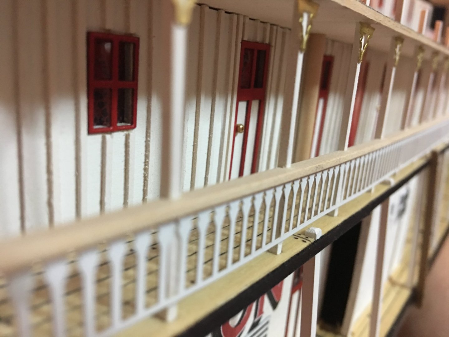
I have all of the sconces installed as well as the boiler deck railing. I just need to get a coat of paint on the sconces. I also decided to add a hand rail to the railing. the PE railing just looked too plain there by itself, and adding the hand rail gave it more definition.
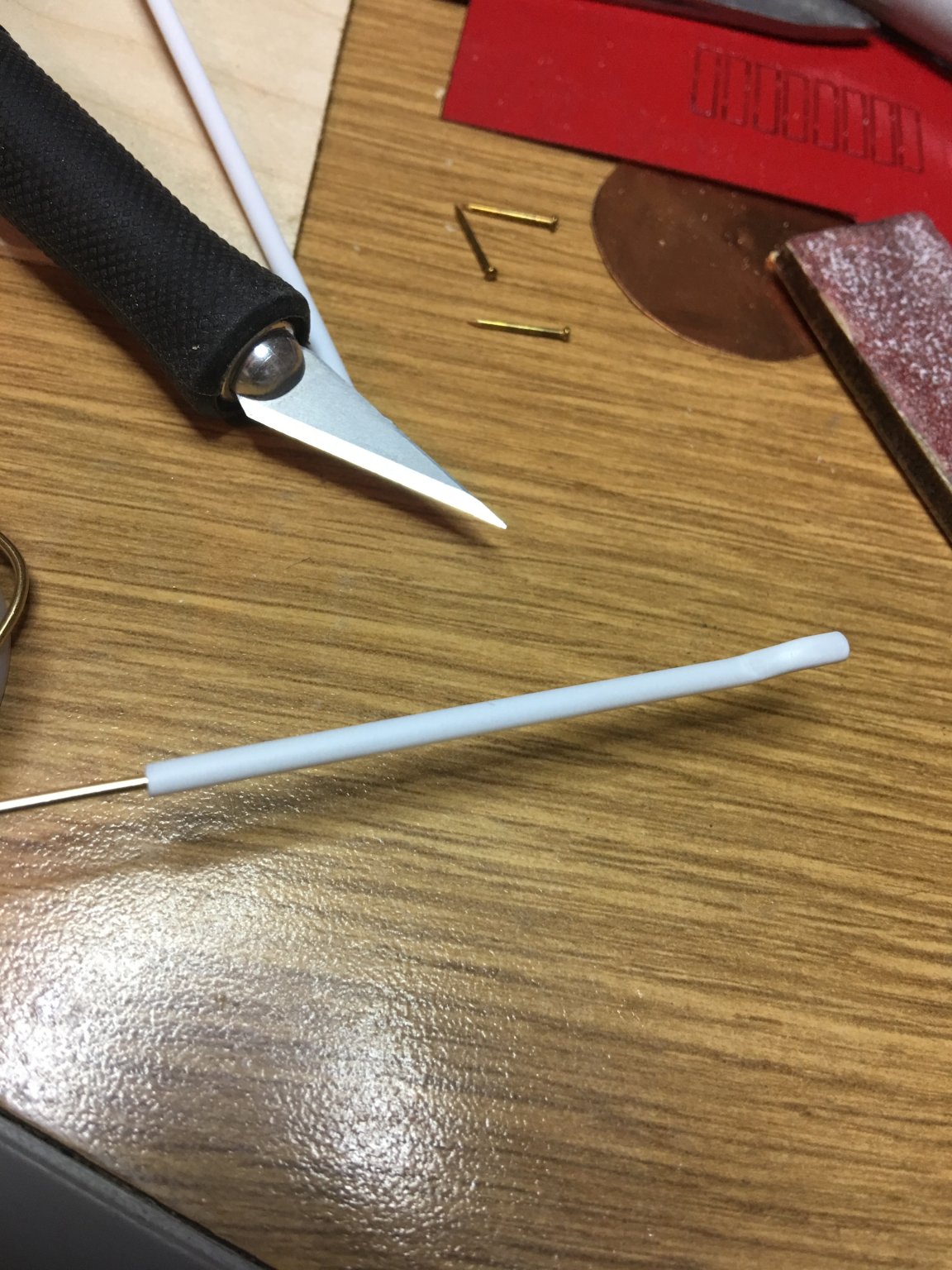
Another little detail I added were the downspouts on the pilot house. A little something I noticed in the old pictures on the U of W website. There are also a couple of these I will be adding to the Texas deck as well, once the roof has been installed. These are made from 3/32" polystyrene tubing. I tried heating and bending it first, but I just couldn't get the shape I was looking for. So I ended up inserting some brass wire in the ends of the tubing, heating it, then bending it with needle-nose pliers. This worked out perfectly and the shape held just right.

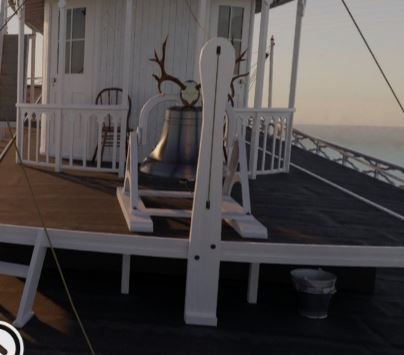
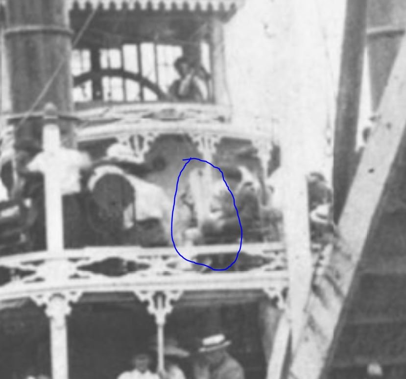
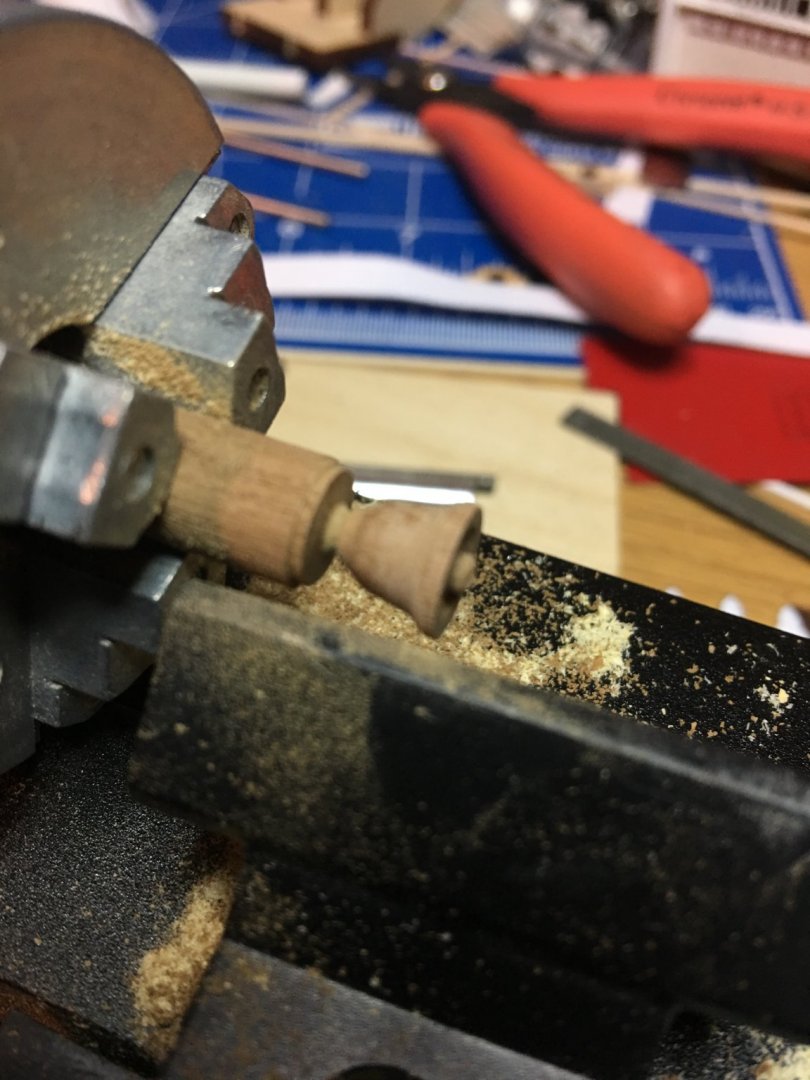
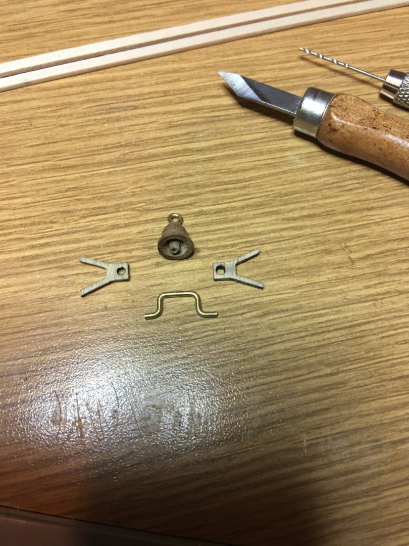
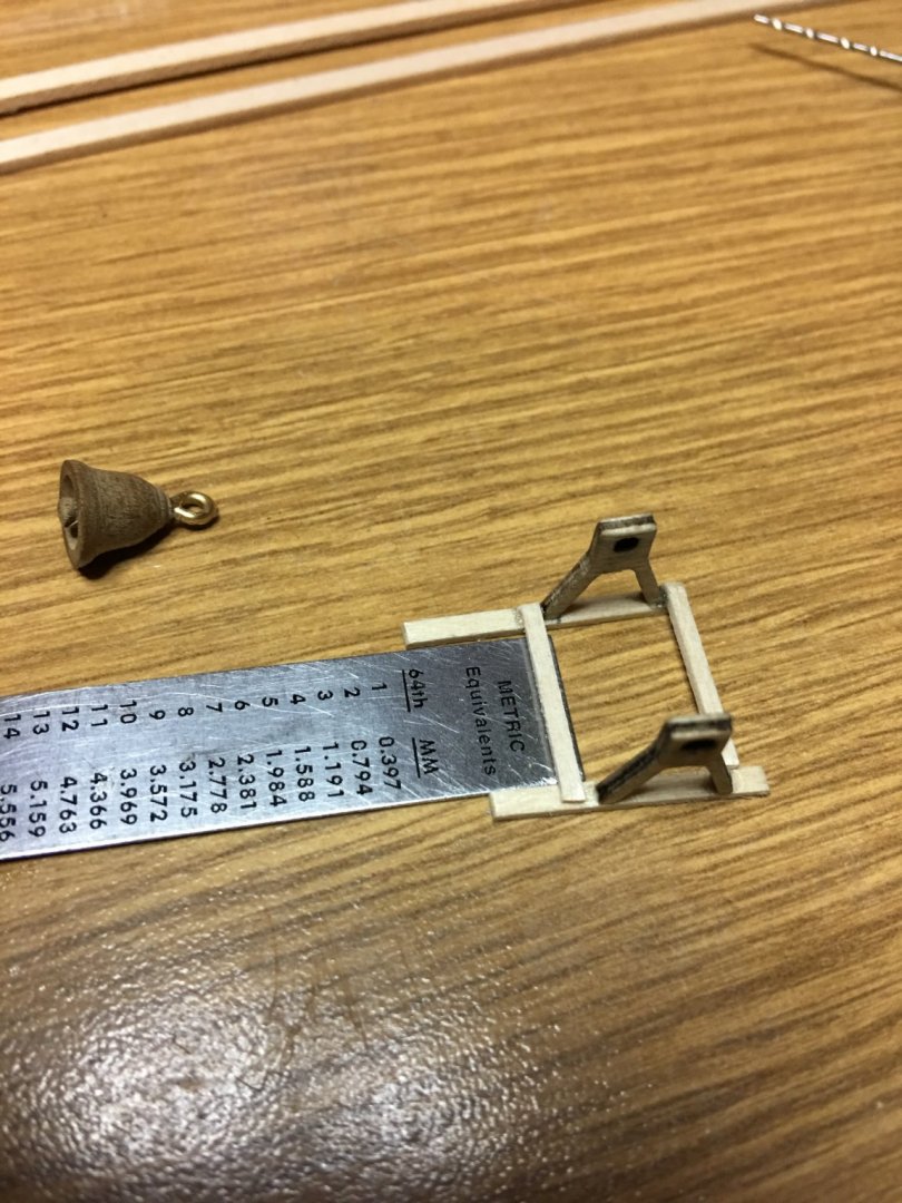
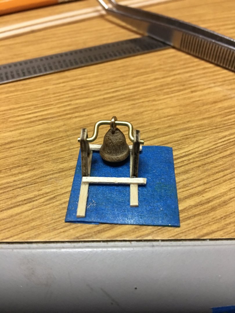
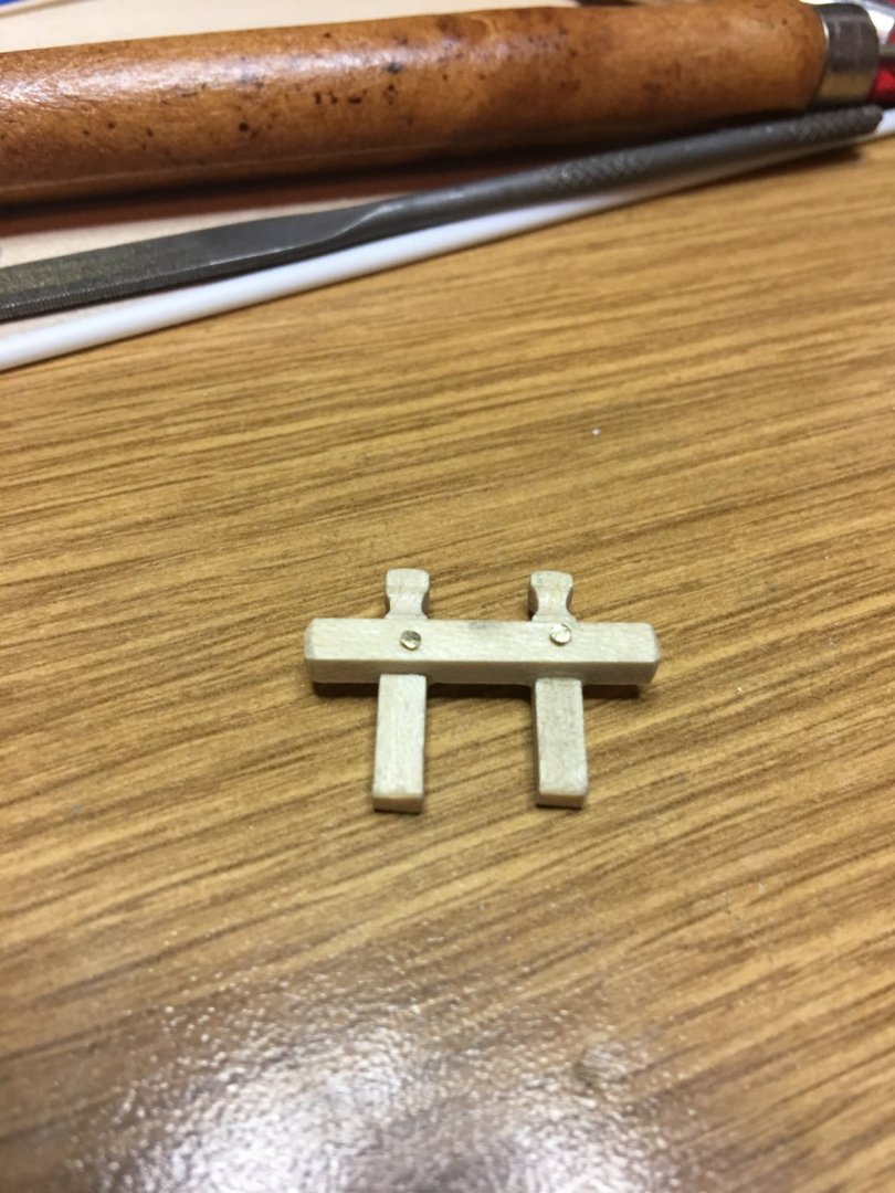
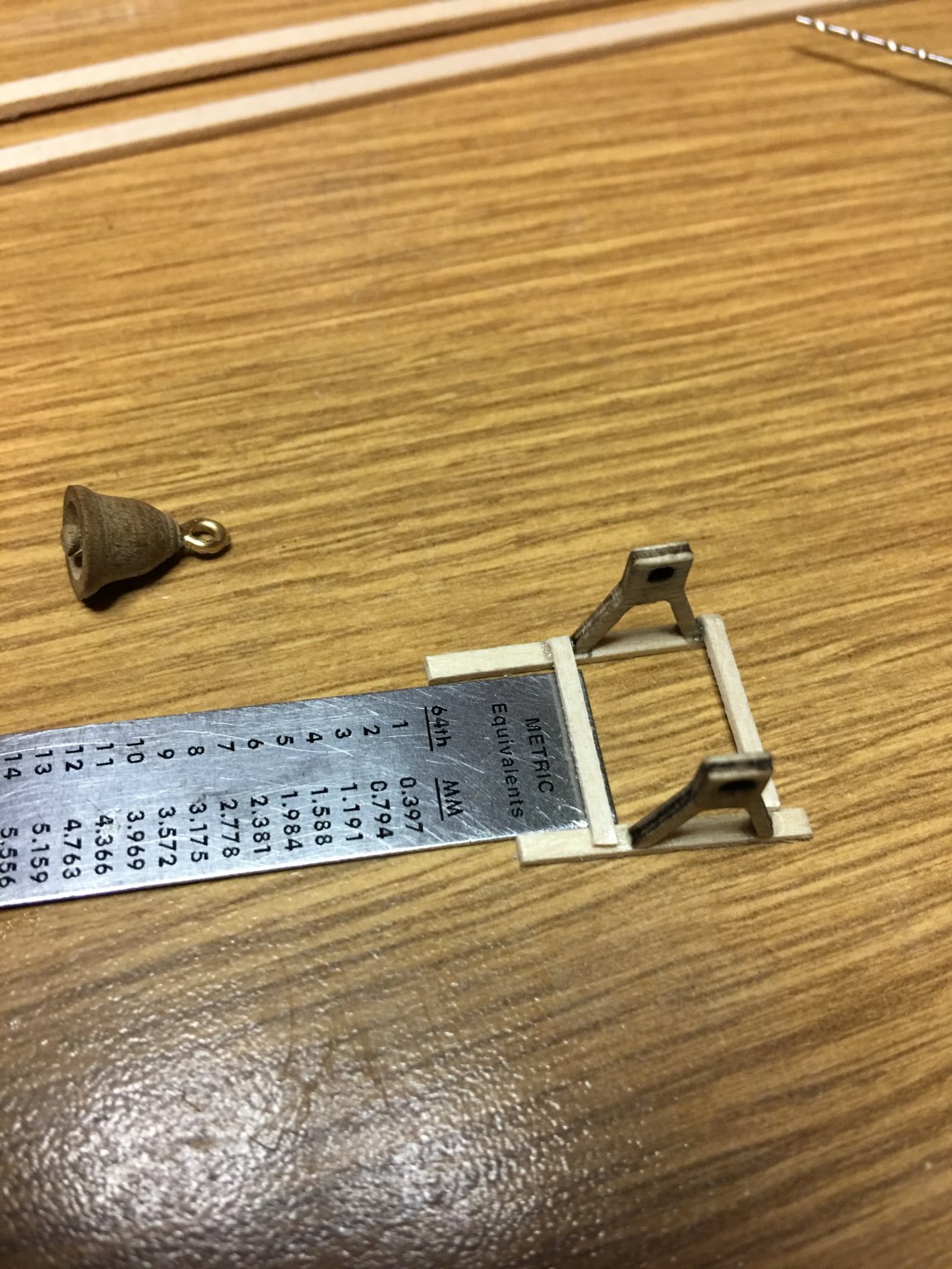
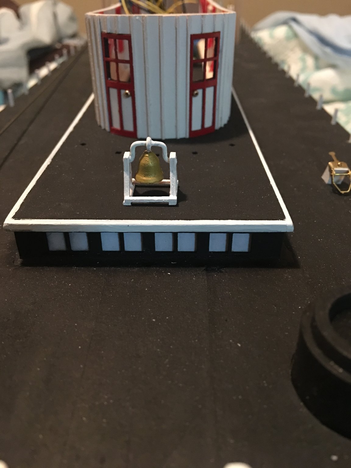
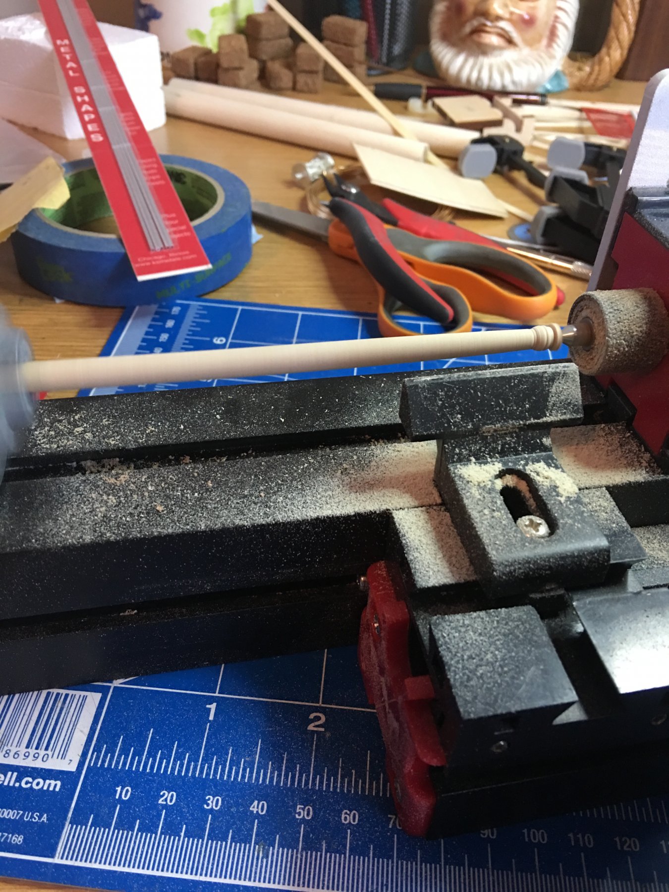
Next I started on the bell. Again I wasn't too please with the Britannia one. To me it seemed a little small. So I grabbed up some spare 1/4" walnut dowel and turned one down on my mini lathe. I think it came out pretty nice. Then I used a piece of 18ga wire to make the holder and used the side braces that came with the kit, along with a couple of supports to modify it slightly. Then I mounted it in place on top of the Hurricane deck roof. I will work on making the board the holds the pulleys for the clapper rope and get that in place later. Not really sure of what this board was called, but I noticed it on the 3D rendering and confirmed from the old photos from the U of W website. I want to also add the antlers to the bell. I had the perfect set, but I couldn't bring myself to scalp my grandson's toy deer. I'm sure I can find another plastic deer at a toy store somewhere.

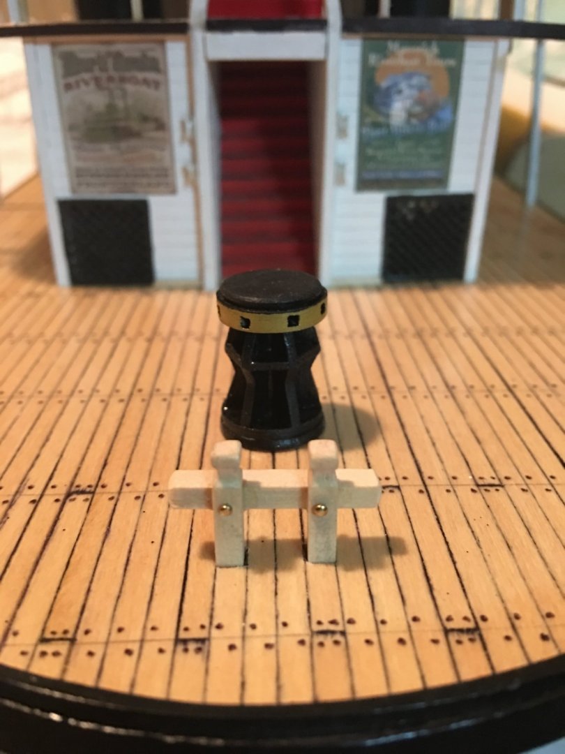
I was also able to complete the bit on the fore-deck and get it installed.
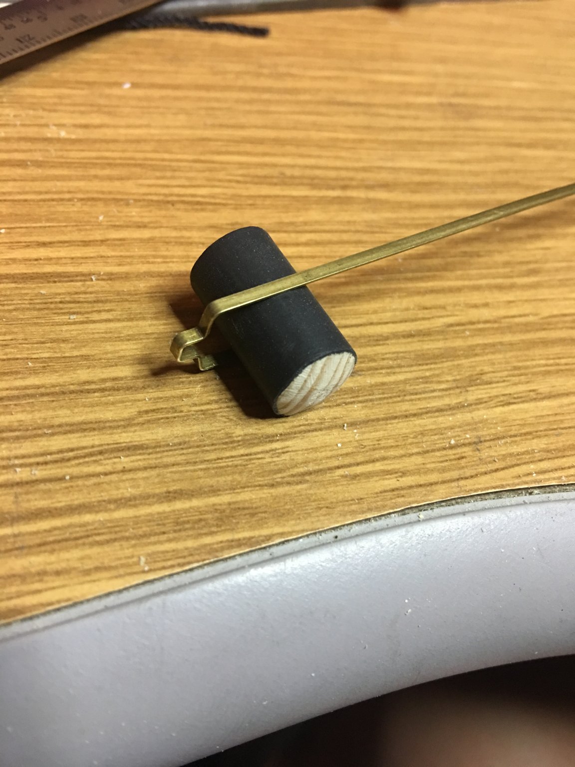
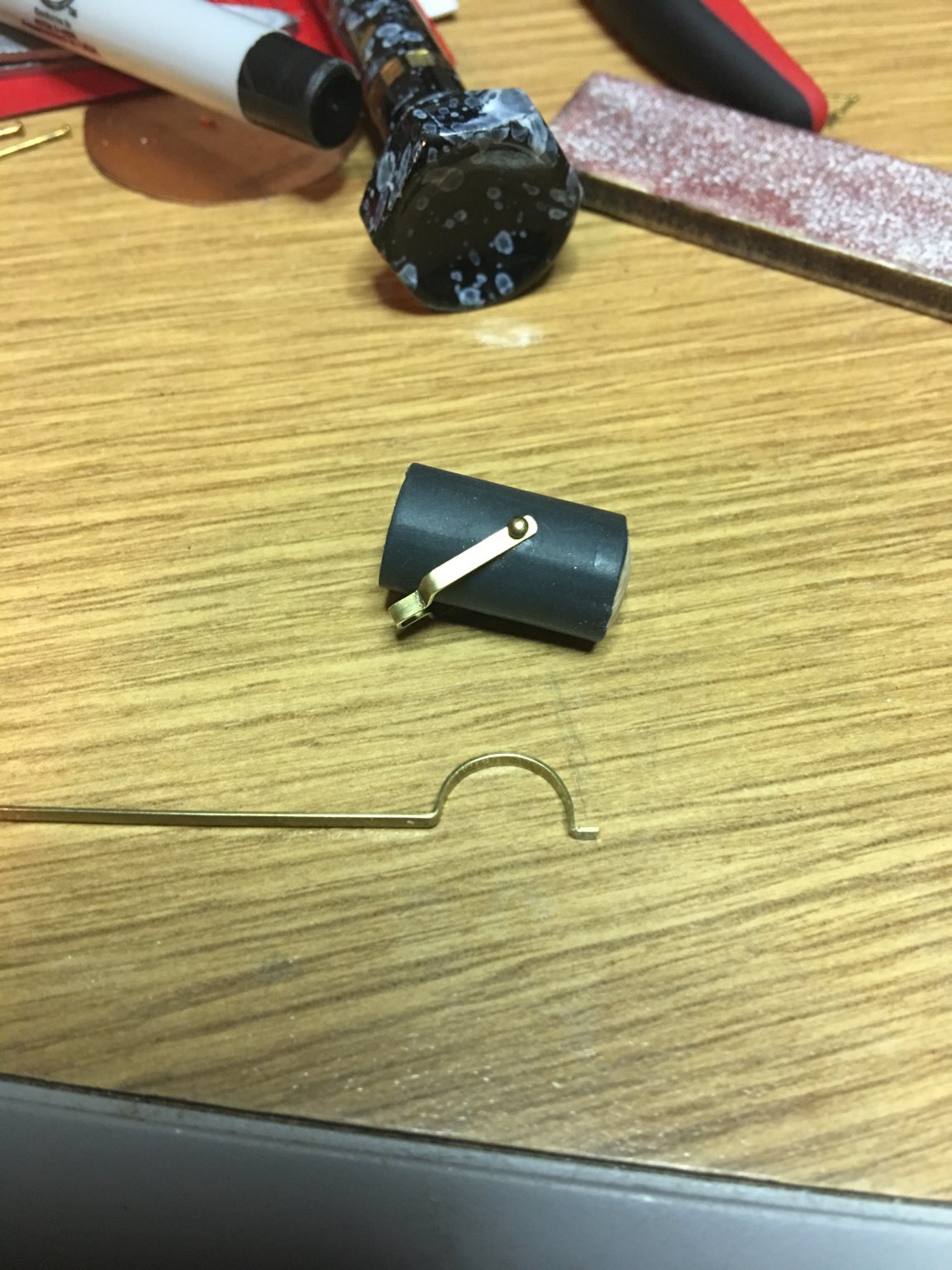
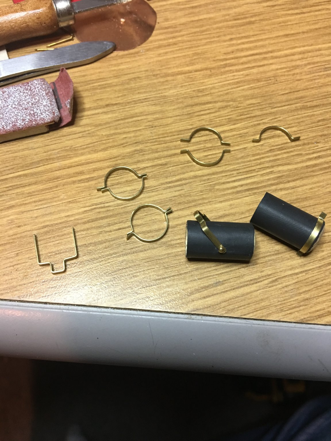
Lastly, I started working on the carbon arc searchlights. I formed the housings from 3/8" dowel and used flat 1/16" brass strips for the mounting swivel bracket and the clamps. I then used some heat shrink to wrap it in to give it a smooth look on the outside. I was still in the process of getting these assembled when I got sidetracked on the hand rail. I may keep these out of the boxes and work on them from when I have a spare minute or two while I build my shipyard. I think I have a box somewhere that has a bunch of old plastic car models in it. I'm thinking of using some of the clear headlight lenses from these to make the lenses for the searchlights. Trick is, I have to find the box first. Otherwise, I am going to have to come up with some other way of making them.


Anyway, that is all for now. As always, thank you all for the likes and for looking. Until next time, Happy Holidays to all.
-Brian
- GrandpaPhil, Canute, VTHokiEE and 6 others
-
9
-
Good afternoon everyone,
Thank you all for the likes and information.
Blighty, I do plan on lighting the entire model, from the pilot house down to the boilers. I am still working on a way to try and light the red and green navigation lights on the smokestacks. This is definitely proving to be a bit of a challenge without the wiring being seen. I'm sure I can come up with something though. I am also toying with the idea of adding the carbon arc searchlights and somehow lighting those up as well. We'll see how this challenge goes.
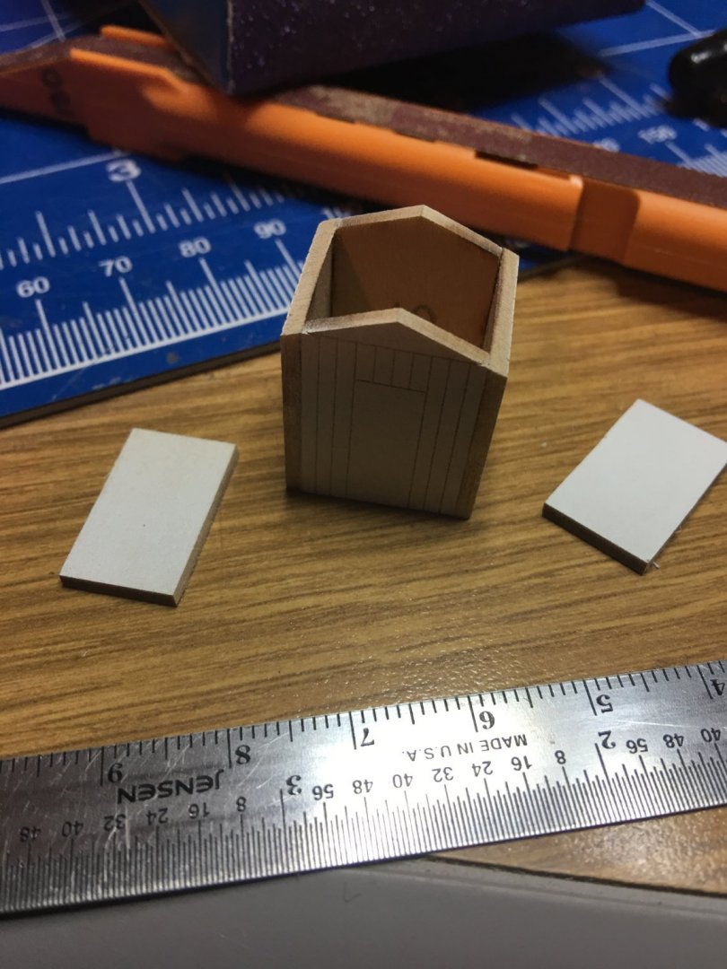
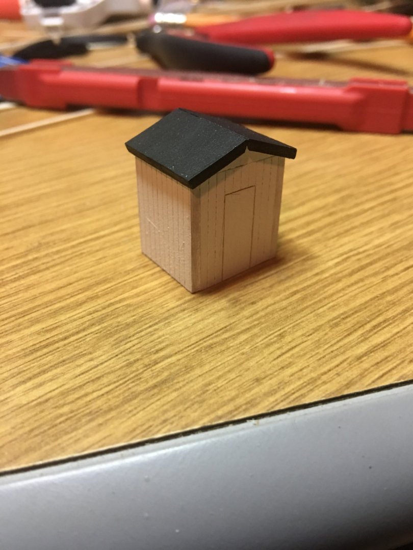
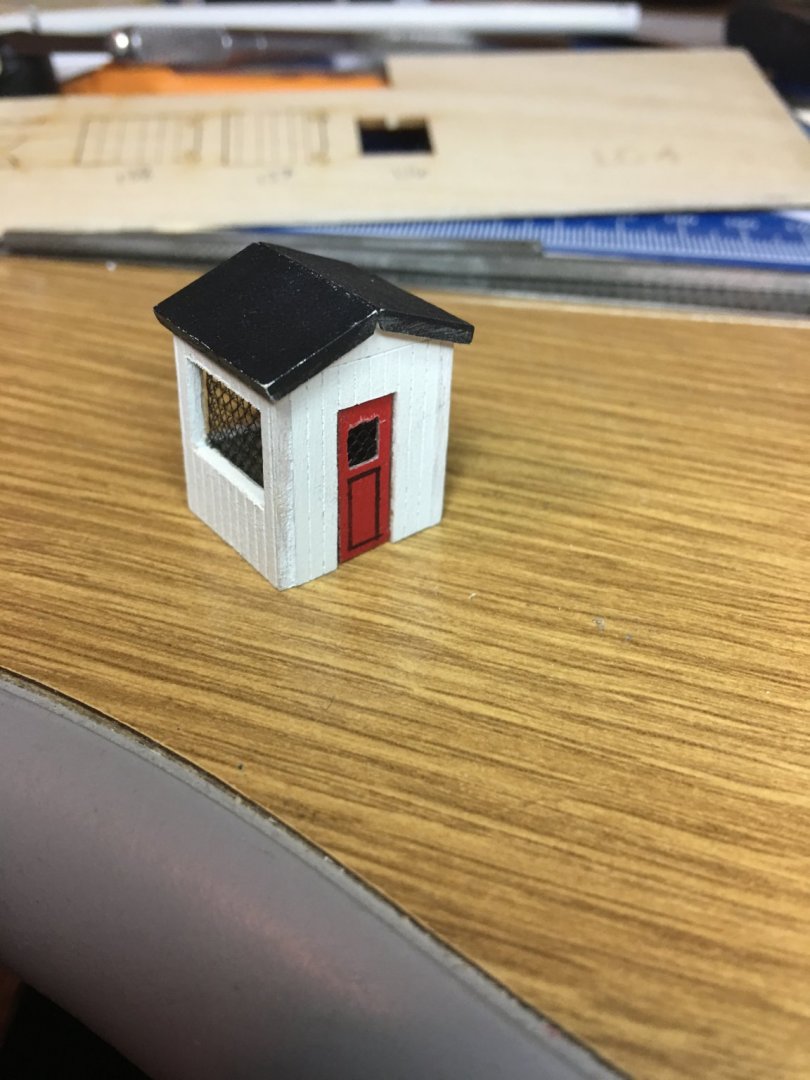
I managed to get a little accomplished this week. The chicken coop and the capstan.
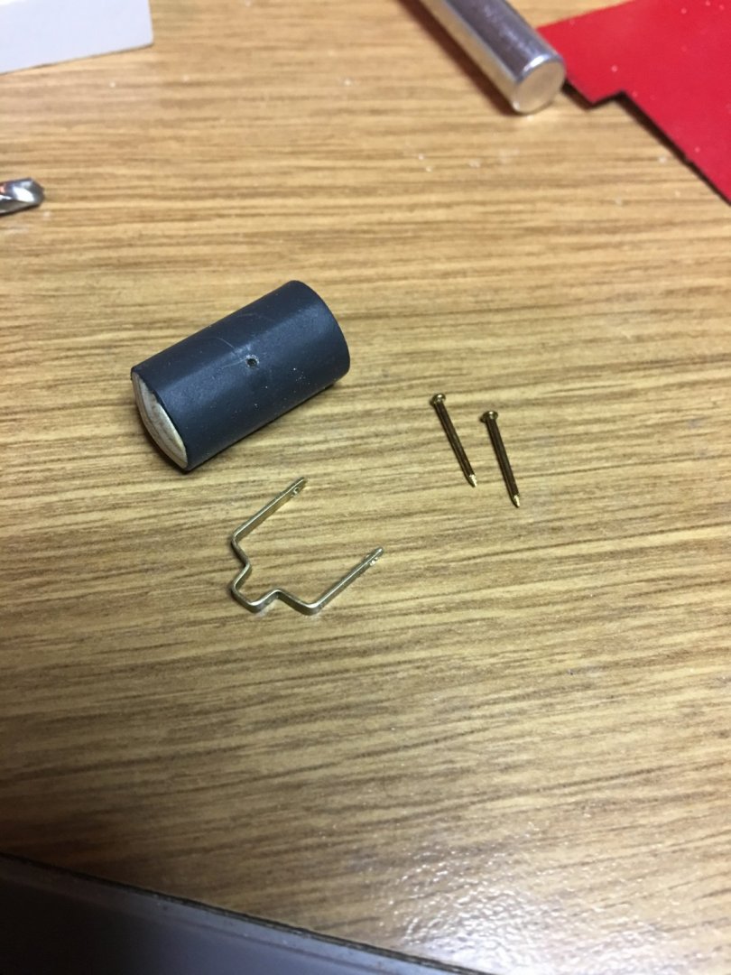
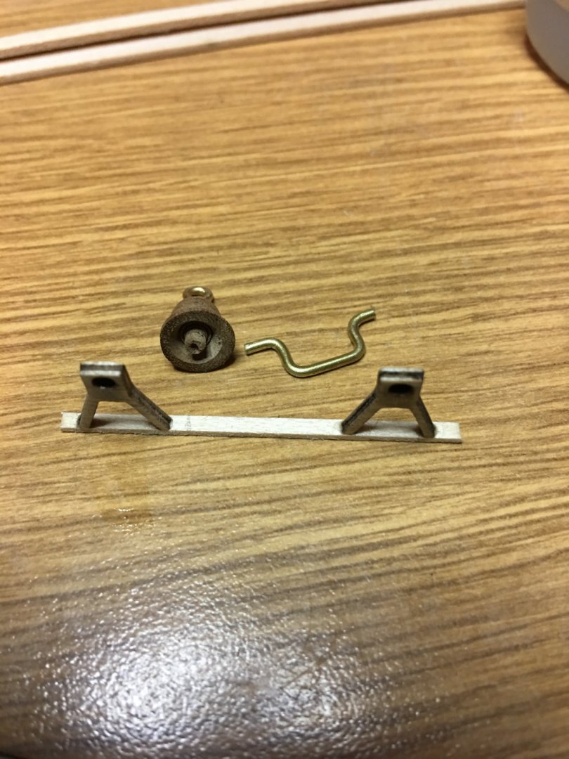
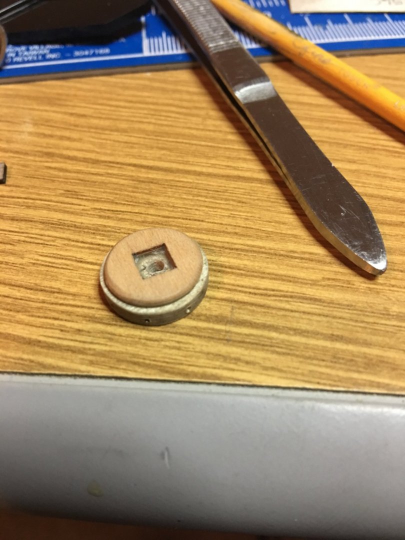
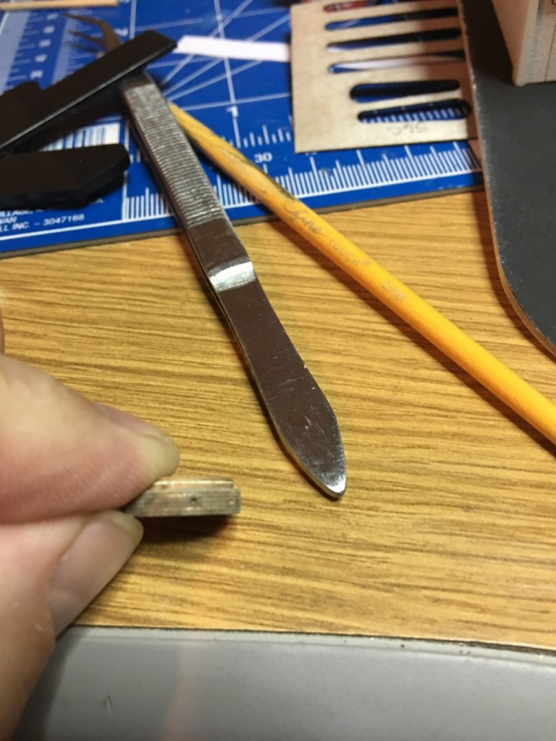
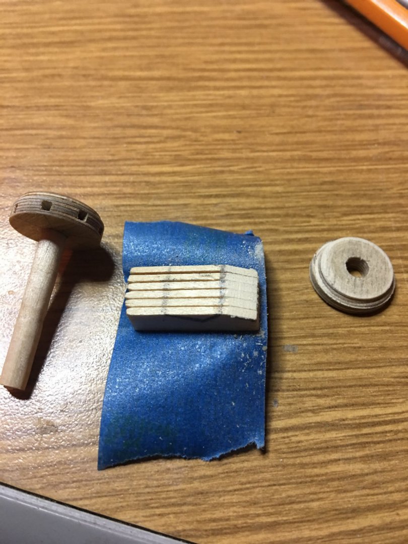
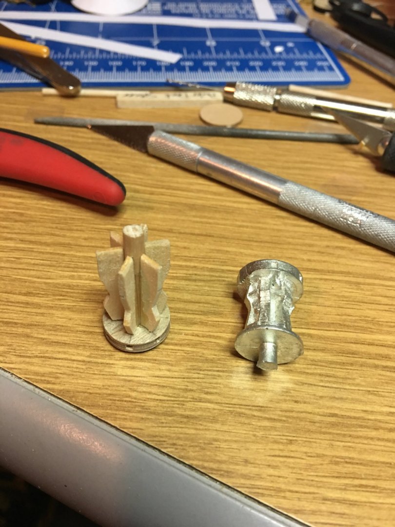
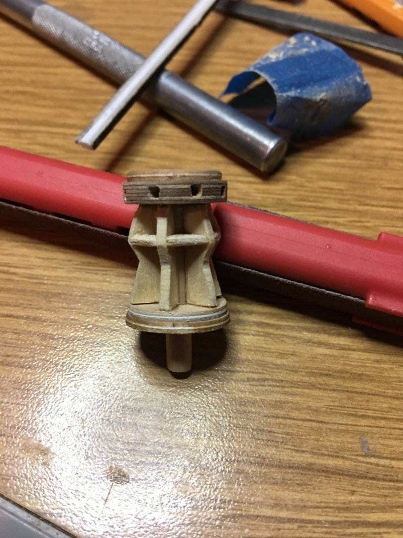
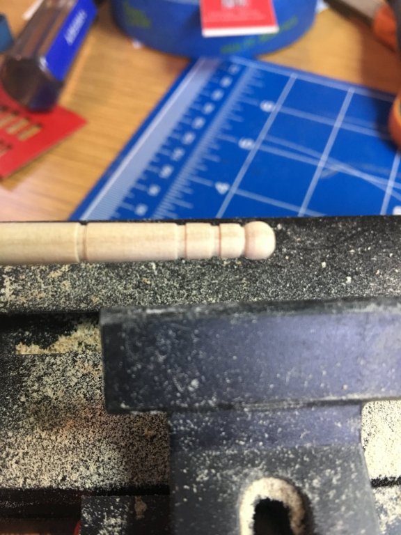
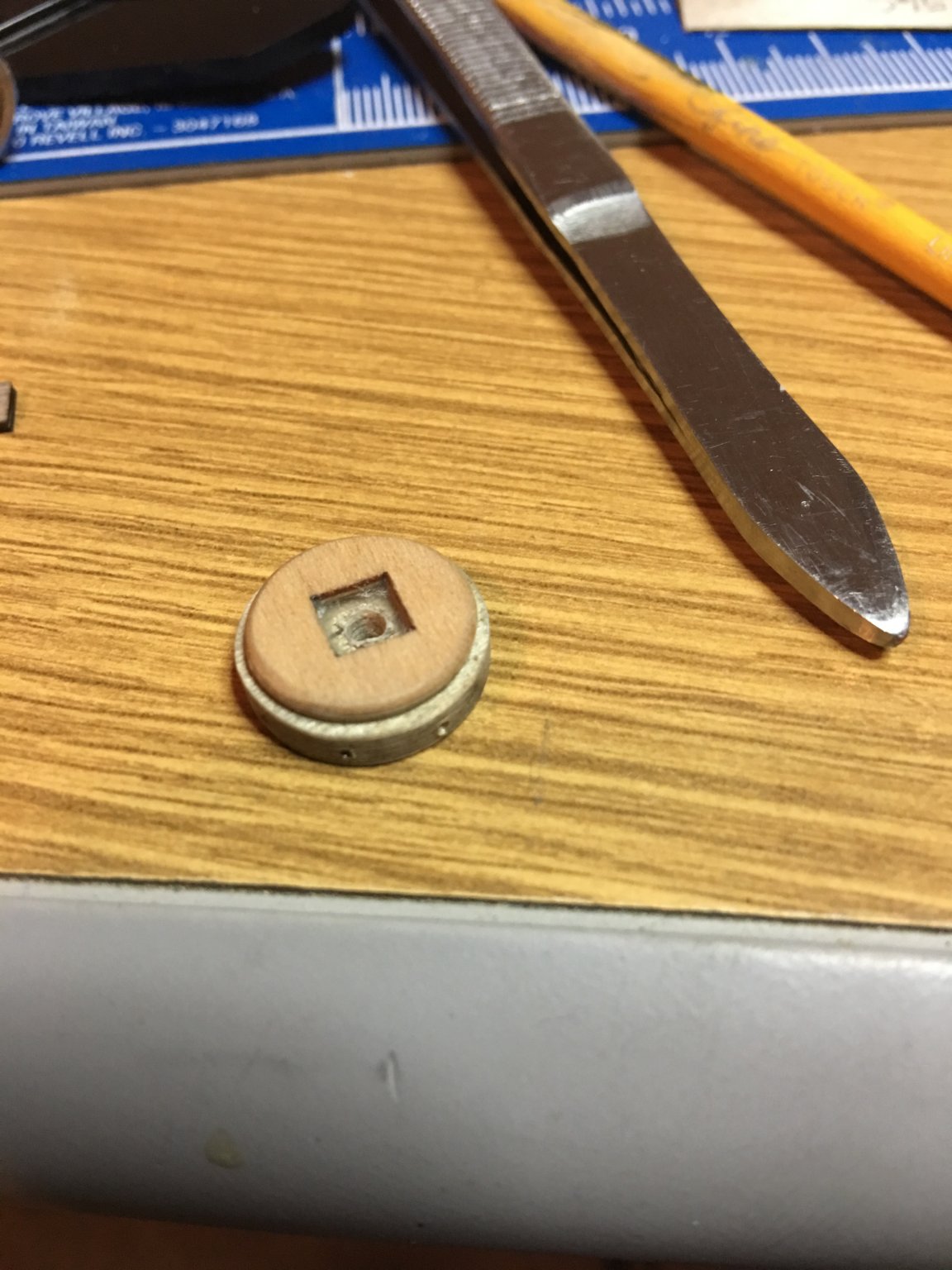
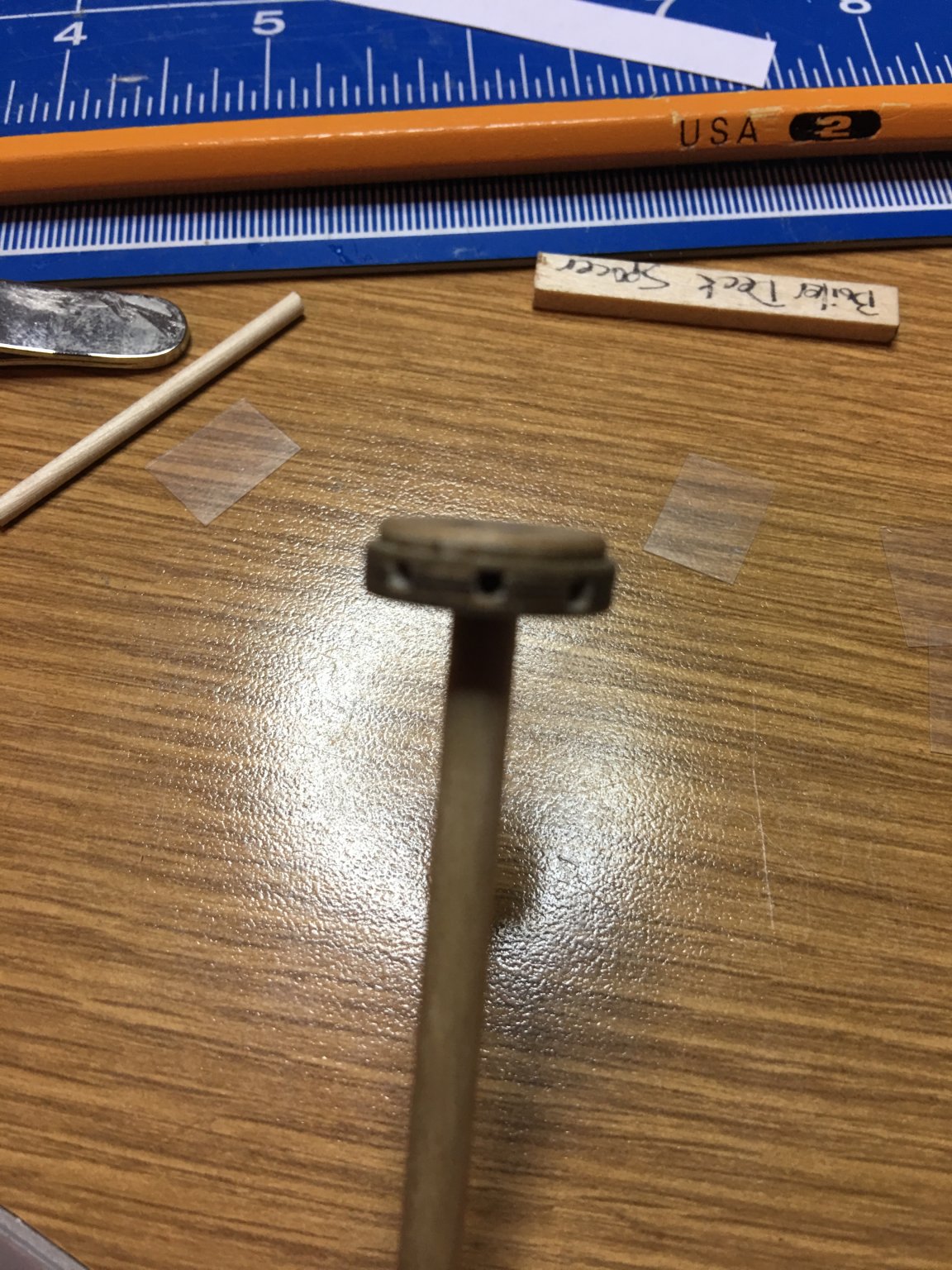
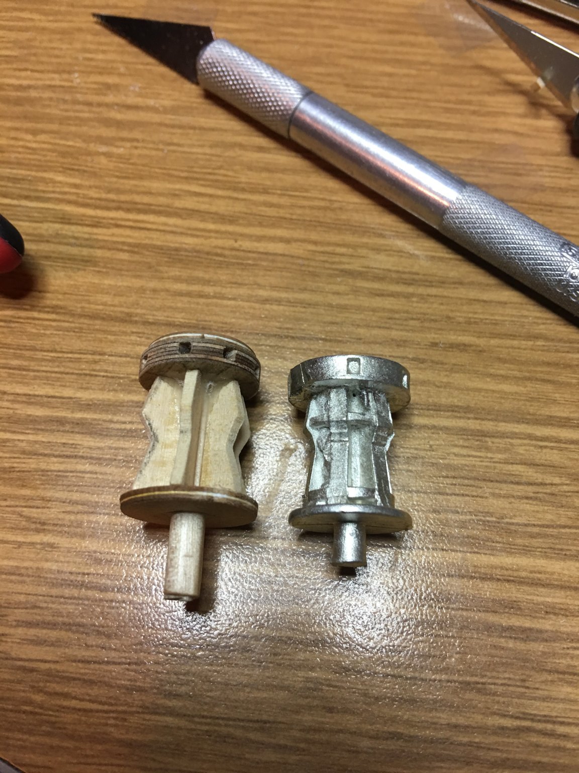
As I mentioned in a previous post, I am not a real big fan of the brittania fittings that come with the MS kits, and anywhere I can scratch build the pieces I will. The capstan being one of those pieces. The kit supplied one was poorly cast and was terribly out of round so here is the third a final version of my scratch built one.


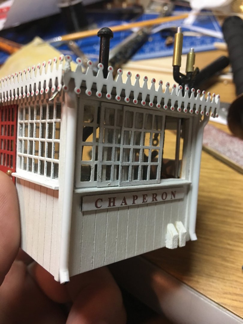
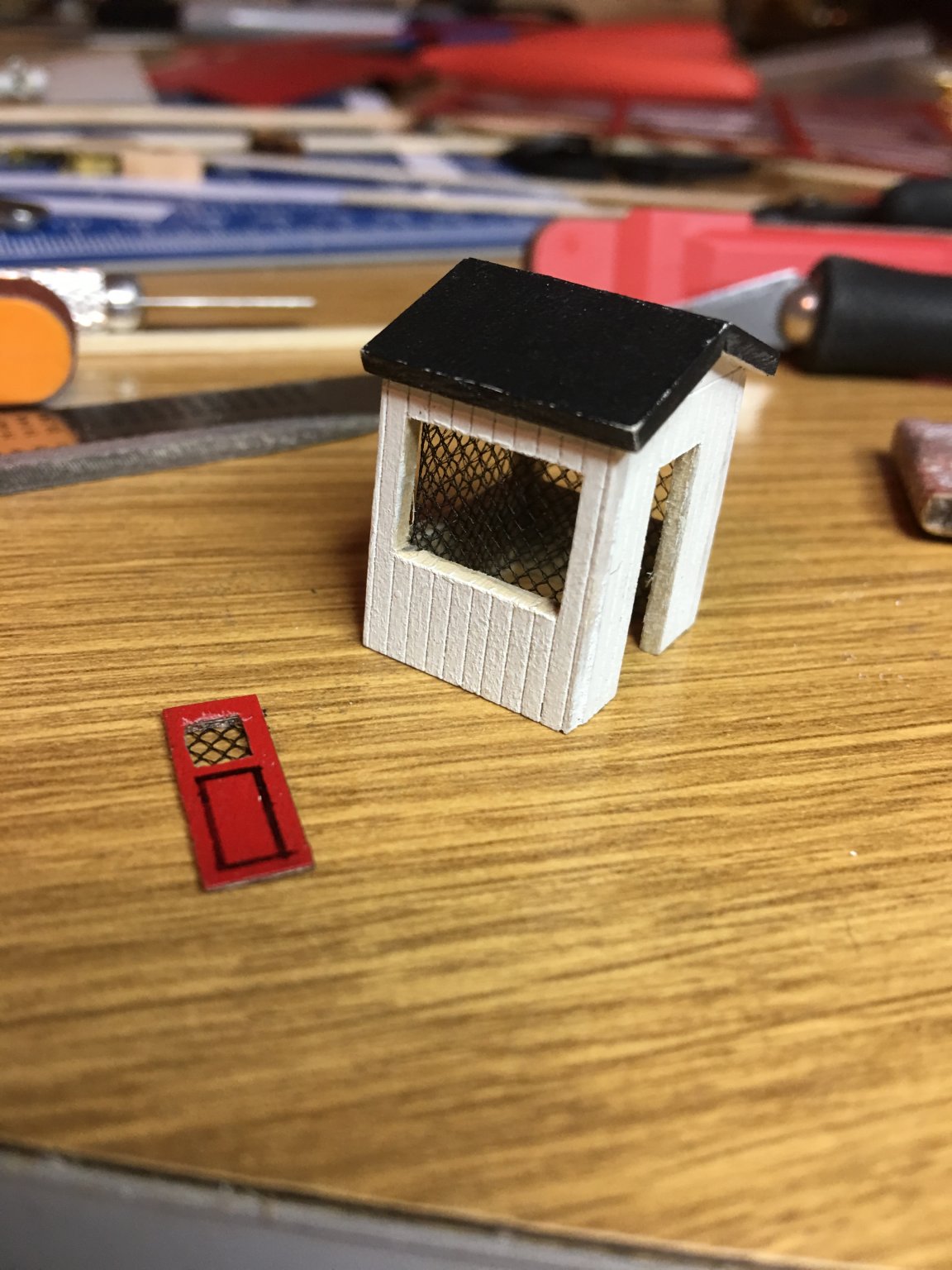
The chicken coop was a little lacking in details as well, so I added a few little touches to spruce it up. I was looking online for some 1:48th scale chickens to add to it, but couldn't find any. I think this should be good enough though. Maybe my version of the Chaperon is sitting at the docks waiting on a resupply and the chicken coop is empty.

That's all for now. I am currently in the process of adding the all the decorative sconces and railing to the boiler deck as well as cutting the smokestack crowns from thin copper sheeting. This is turning out to be a bit of a challenge as well. But I'll figure it out, just need to find the right tools.
Thanks again for looking.
-Brian
- GrandpaPhil, Duanelaker, Canute and 5 others
-
8
-
2 hours ago, Cathead said:
Sounds like a good question for Kurt. I stepped in it deep last time I tried to advise you on rudders! Two certainly seems like the standard that I've seen, but take that with a salt mine.
Aww come on Eric, I can't suck you back into my rudder conversations again?
")
Kurt,
Thanks for the input. I agree, the website is really neat and has inspired many new ideas and subtle touches to add to my build.
I have seen these photos on the UofW website, but since they were labeled as the Chaperon Towboat, built in 1904, I wasn't sure as to the accuracy of the lifeboat style on this one. I looked at some of the other photos of the 1884 Chaperon and zoomed way in on them and can somewhat make out that a couple of them show flat transom lifeboats, but they are a bit grainy.
As for the configuration changes of the 1884 Chaperon, there are some subtle differences that I have noticed through the photos, like the addition of searchlights, the front wall of the main deck by the stair case (open as opposed to being enclosed), the smokestack "crown" (or what ever the decorative top piece is called) has seen several changes, different color schemes on the trim (hard to tell with black and white photos) but it is definitely noticeable on the doors and the "Anchor and Arrow" between the smokestacks, but I haven't seen too may photos that drastically change the look of the boat structure itself.
As for the third rudder, I am seriously contemplating adding it. No monkey rudders though. I can't find any evidence that the Chaperon ever had these.
-Brian
-
Hello everyone,
I wanted to pose a question about rudders. I was doing some research on the internet on the Chaperon to find out what style of lifeboat she carried with her. The kit contains the standard britannia ones that bare pointed on the bow and stern, but in many of the old photographs I came across show ones with a flat transom on them.
Anyway, while researching this I found there were several pictures of steamboats in “dry-dock” where they show them with three rudders instead of just two. I’ve seen the additional “monkey rudders” mounted aft of the paddle wheel, but this third rudder was mounted to the hull in line with the other two.
I’m sure the timeline would dictate the evolution of the boats, but my curiosity got the better of me so I went down the rabbit hole and started looking into rudders (again). I really couldn’t find a whole lot of info on when they started putting three rudders on steam boats or if there were just a few one-offs where the shipbuilders were experimenting with maneuverability of the boats. Then I stumbled across a site of a gentleman from Germany who put together beautiful high-res drawings as well as a 3D virtual tour of the Chaperon. That’s when I saw that he had also included three rudders on his drawings. So being the novice in the world of steamboats, I figured I’d pose this question to the experts. Personally I think it’s pretty cool looking to have three rudders, but I would till like to keep my build as historically accurate as possible.
Any thoughts on this?
BTW: here is the link to the site I was referring to. I’m not real sure of it’s accuracy, but it does resemble the MS kit.
https://www.jensmittelbach.de/steamboats/chaperon/index.html
-Brian
-
-
Beautiful work on such tiny pieces. One slip of the tweezers and those parts can be lost in the void. She’s coming along nicely.
- Brian
- lmagna, Canute, popeye the sailor and 1 other
-
4
-
Eric,
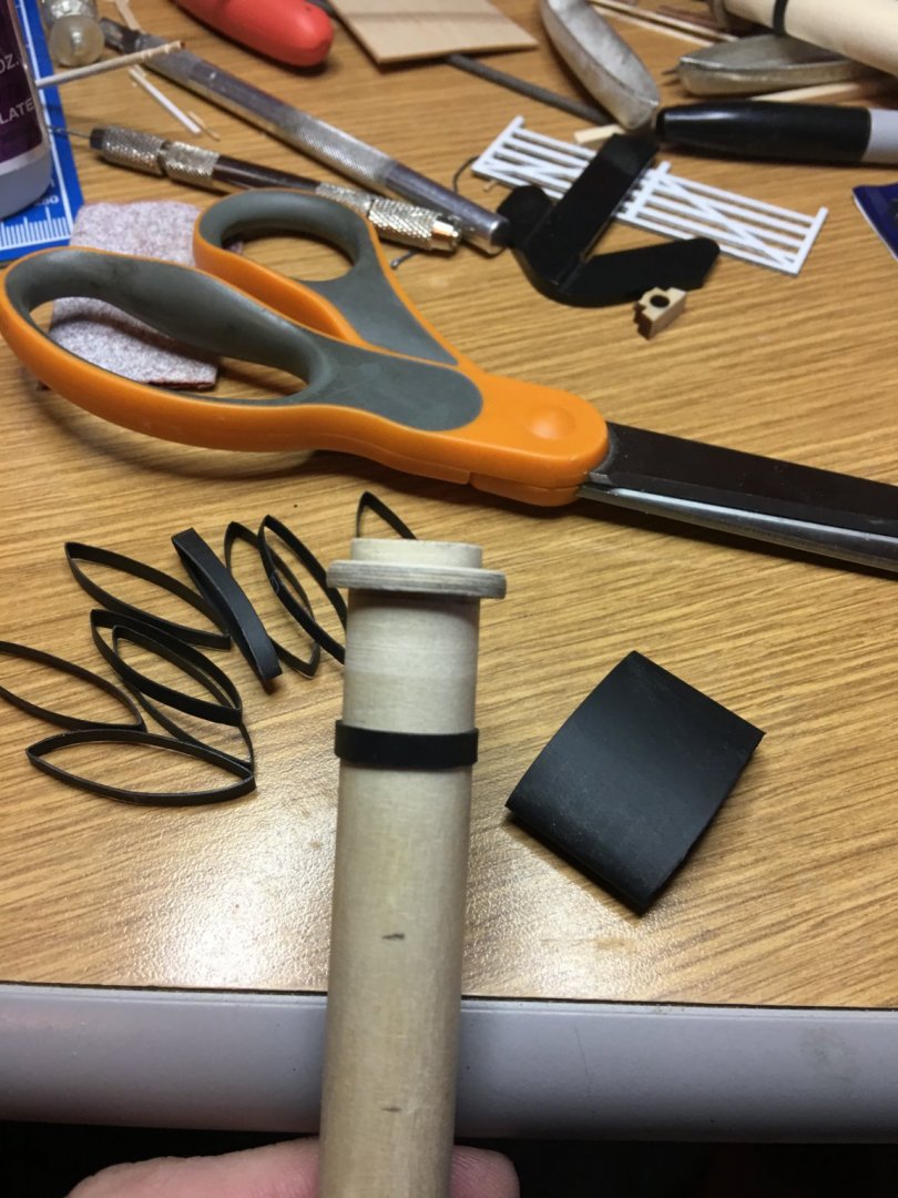
I have been using heat shrink for years and it holds up well in all types of weather. I use it on the wiring of my trailers that sit in the sun/rain/snow year round and haven't had a single connection rot away. The only issue that I had with doing the bands this way was I had to secure them in place with a touch of CA because they tended to slip on the wooden dowel. There are some heat shrinks that have a heat activated glue on the inside of them that helps seal the connection and would probably work a little better in this type of application, I just used what I had on hand.
-Brian
-
Greetings everyone,
It has been a while since my last update. Unfortunately, end of year work travels and work on the ranch has taken a considerable toll on my ship building time. However, winter is fast approaching which means colder weather to stay indoors and in the shipyard.
I was able to accomplish a few tasks on my build, but not a whole lot. I figured I'd go ahead post what I have so far.
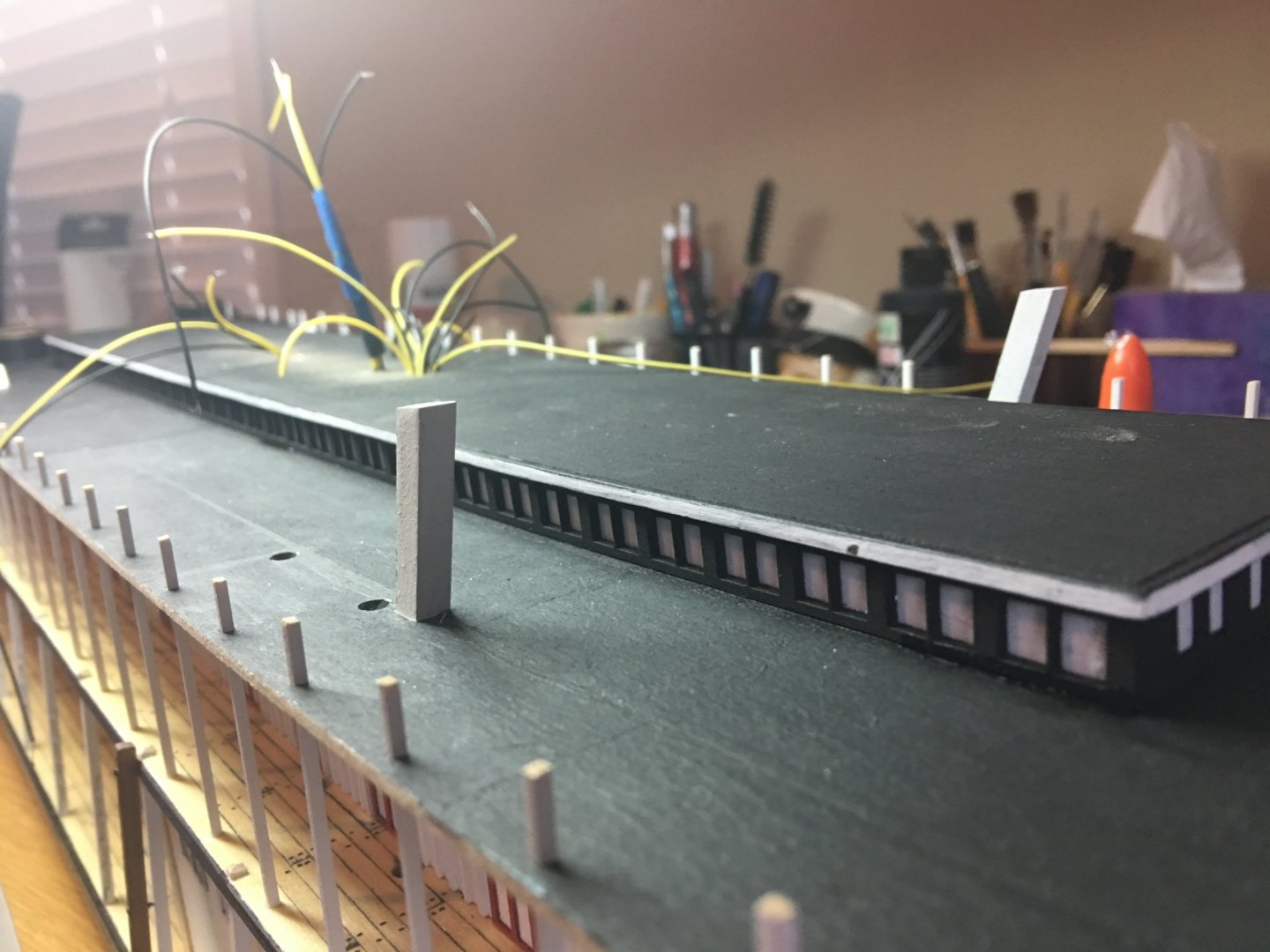
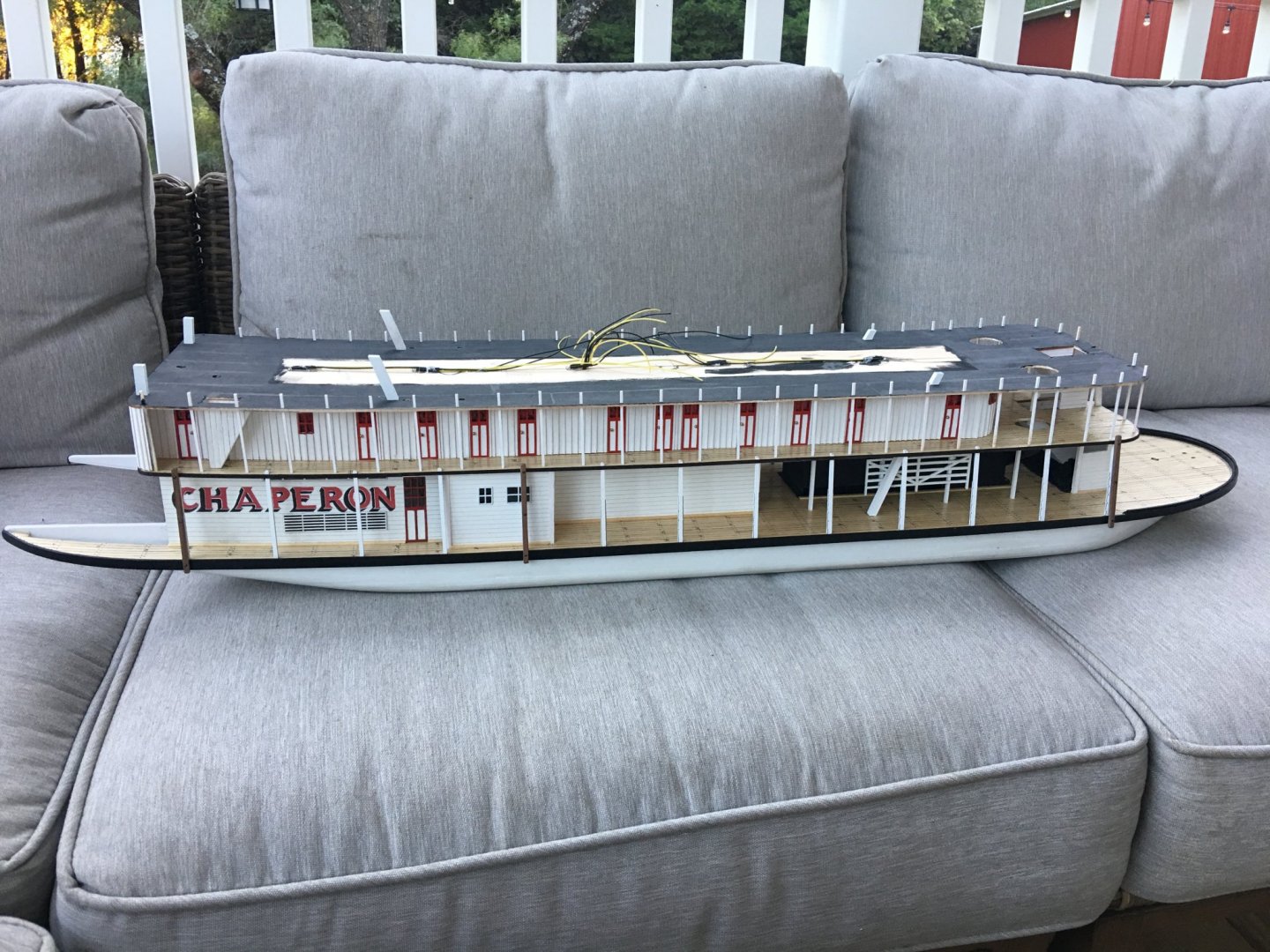
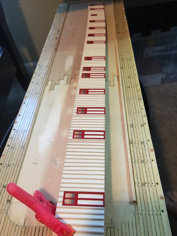
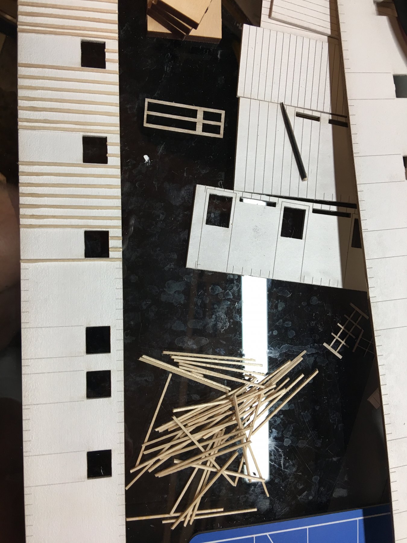
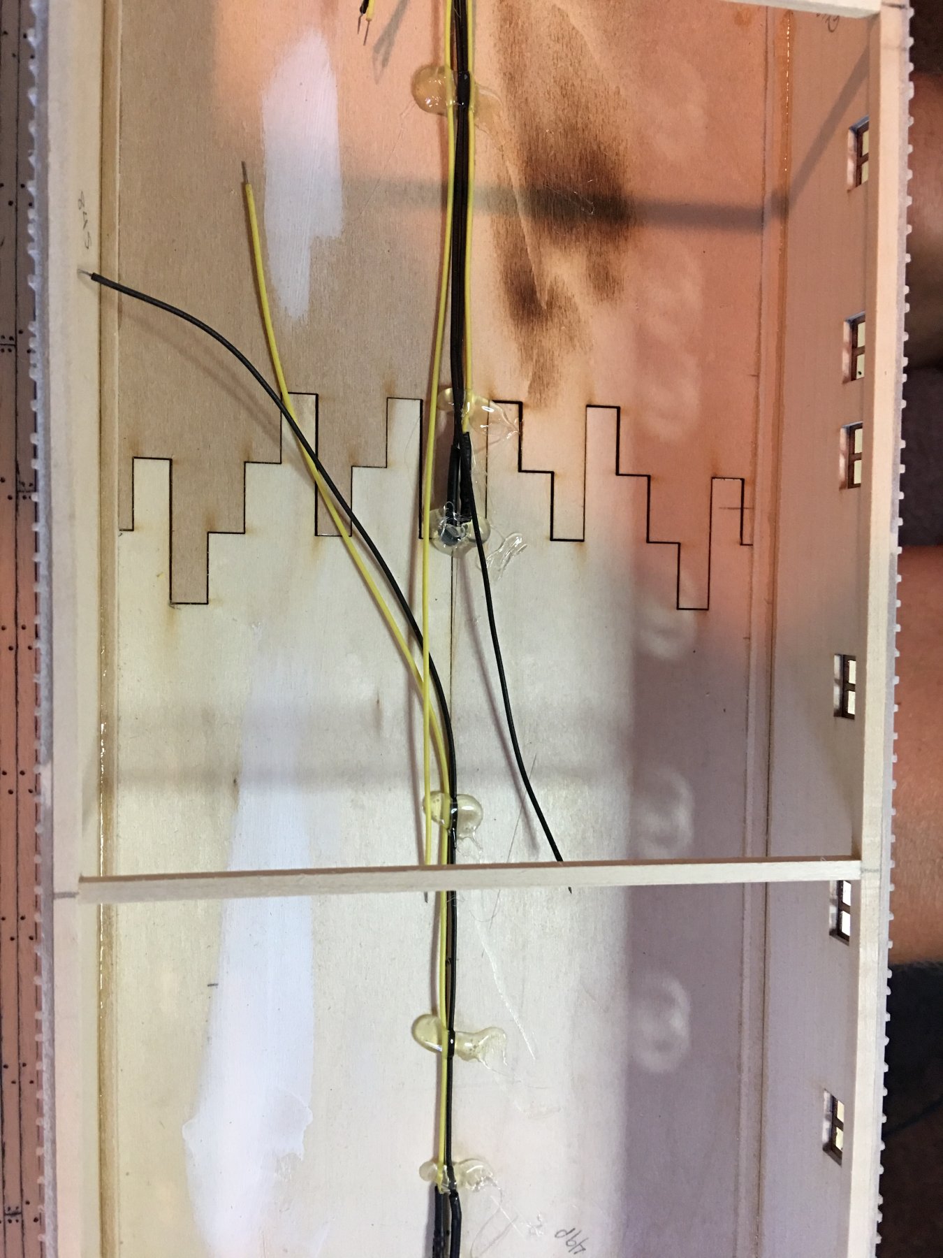
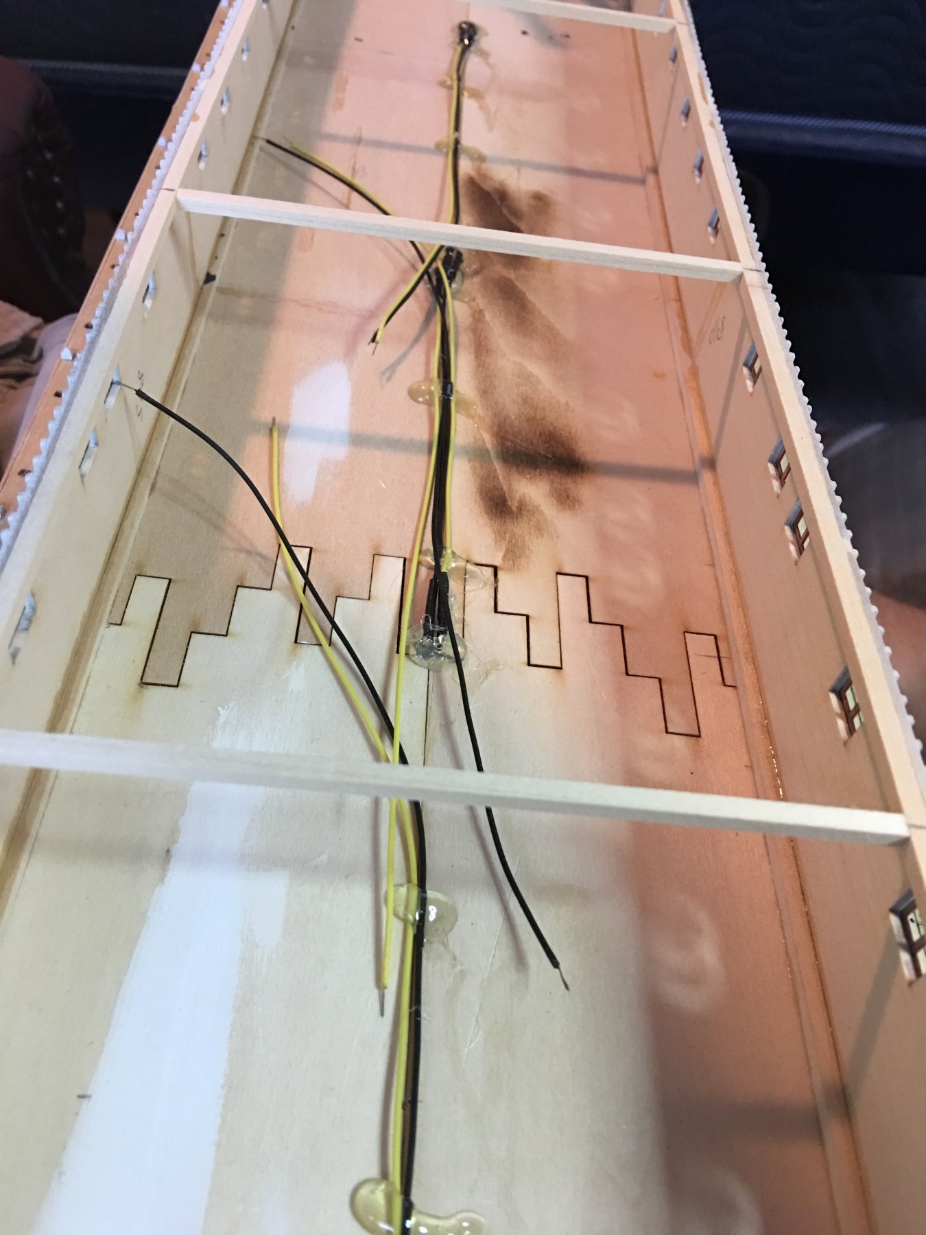
Work was completed on construction of the Texas deck. All those little battens to glue into place. A monotonous task to say the least, but I got it done. I still need to hang the curtains and secure it to the top of the Hurricane deck, but I need to get the LED wiring dressed up and run the main power wire from the bottom. I was going to go with a battery powered solution, but I couldn't come up with a way to house the batteries that I liked. So I decided to just run an external power source. (more pictures on that later)
Next I fastened the Hurricane deck to the top of the Boiler deck and pulled the wiring through. I used thin tissue paper to cover the windows to hide the LED's that are glued to the top. The tissue paper should provide a nice glow with the yellow LED's.
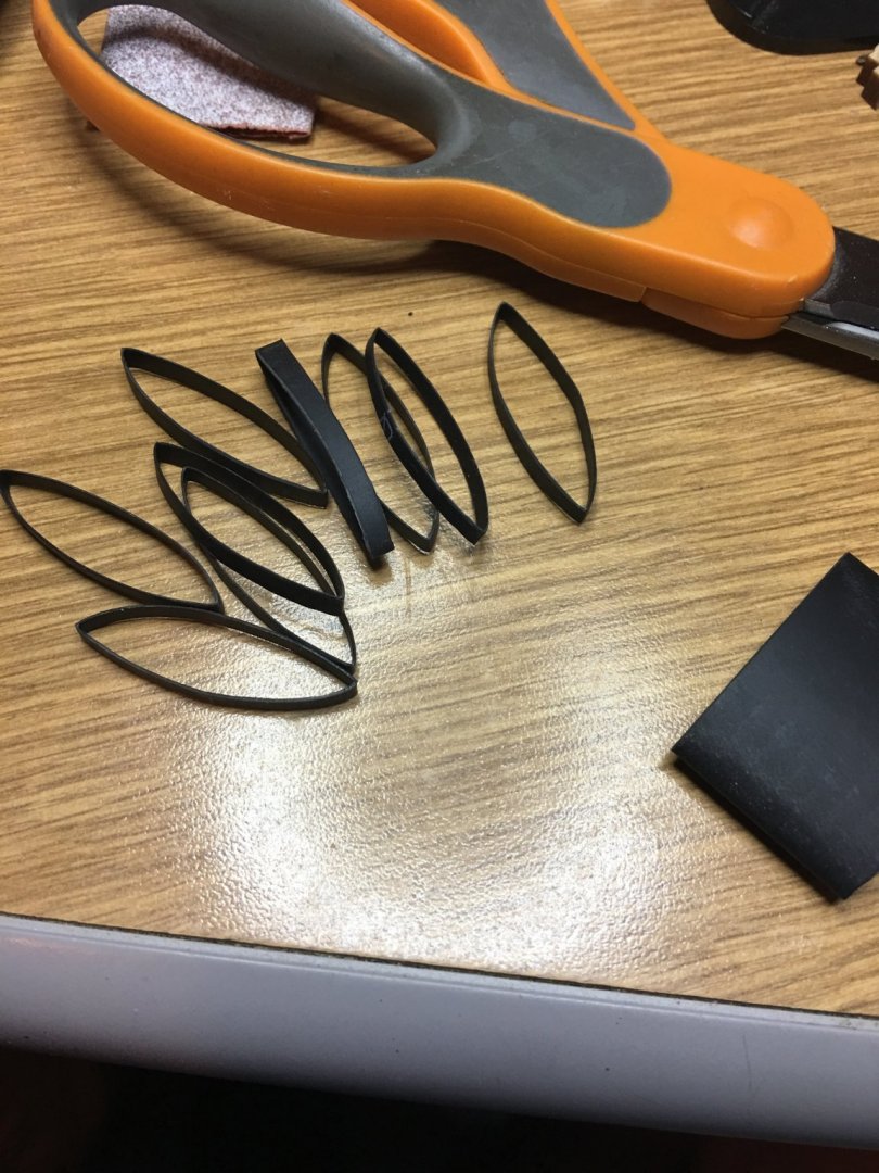
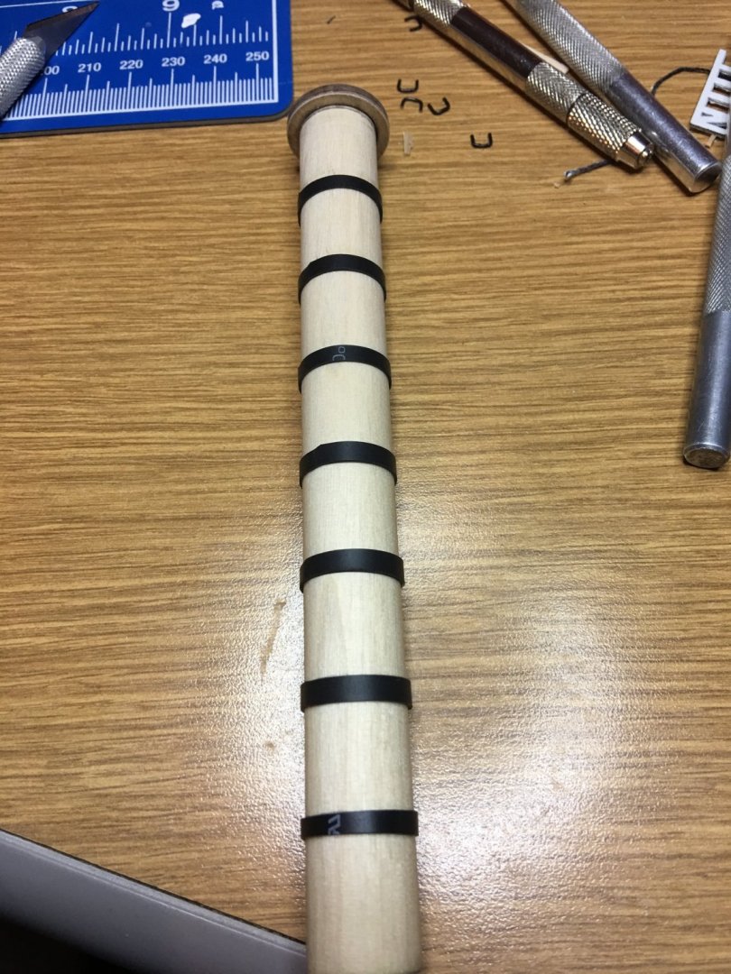
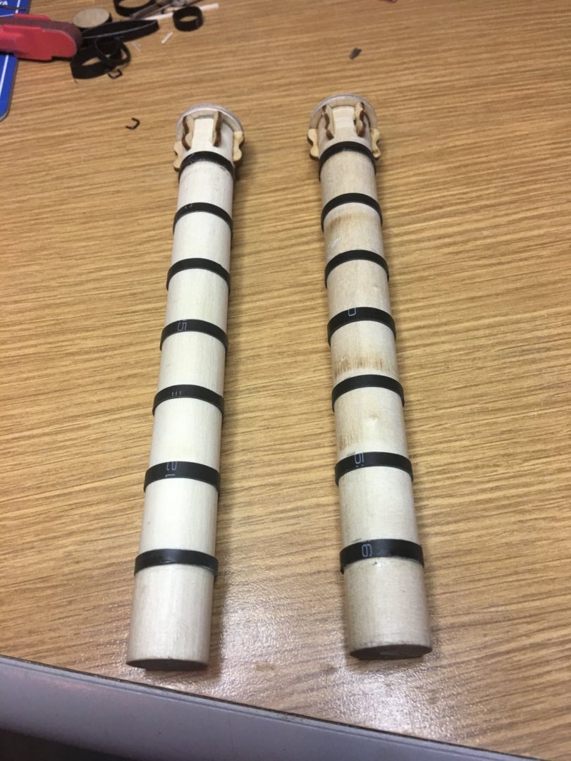
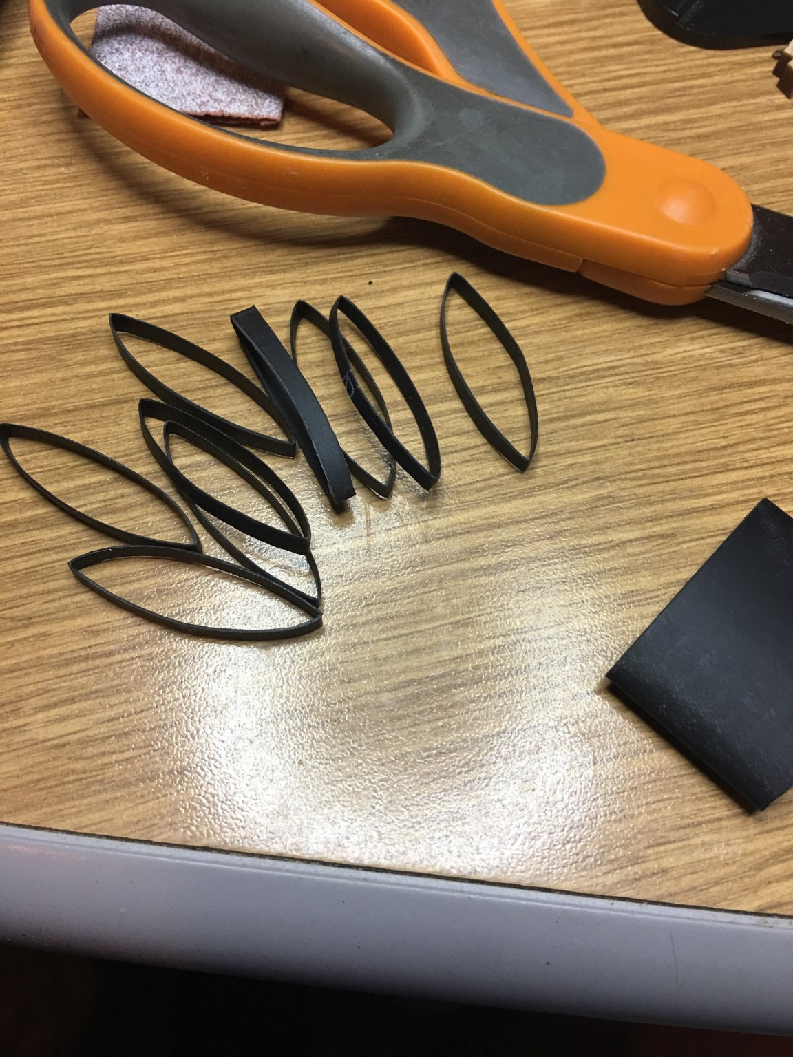
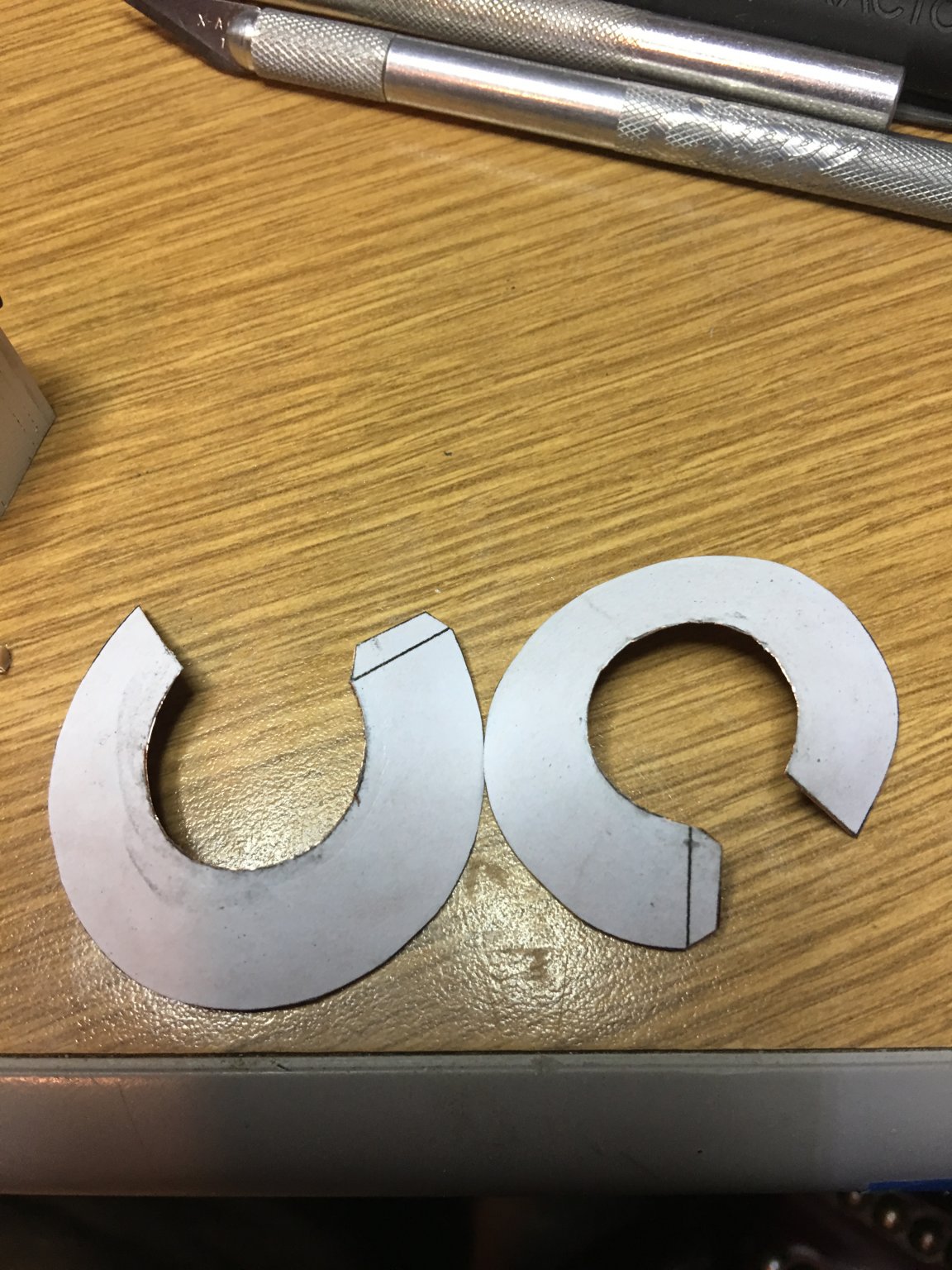
Lastly, I started work on the smokestacks. I tried several methods to simulate the joint between sections. First I tired using some leftover pin-striping I had, but I couldn't get the tape line up all the way around. Next I tried small rubber bands (leftover from the kids braces). Unfortunately, the kids have been out of braces for several years now and most of the ones I had left were dry rotted and didn't have enough good ones to complete the job. So I finally came up with the idea of using heat shrink tubing. I was outside repairing the wiring on my trailer when the idea occurred to me that this would be a perfect solution. So I gave it a whirl. I am actually pleased with the result. All I have left to do is paint them and see how they look. The smokestack caps I made from a sheet of thin copper, in which I pasted the pattern on and cut out with small snips. I am going to use the same method and material for the decorative tops.

That all for now. Hopefully I will be able to get more done with all of the travelling done for the year.
Thanks for looking (and Happy Veterans Day to all those who served)
-Brian
-
Russ,
Thank you for the kind words. Glad I could help.
-Brian
-
Russ,
By the way I forgot to mention, Your build is really looking sharp!
Keep the pictures coming in.
-Brian
-
Russ,
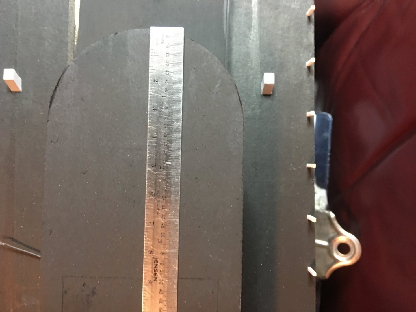
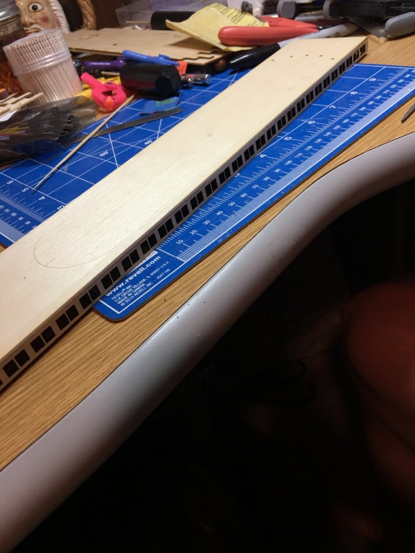
Looks like we are about at the same place in our builds. I almost ran into the same situation when I was "tar papering" the Boiler deck roof when I realized I was covering up the reference lines. Fortunately I caught it on my first run over the lines and ended up being a quick fix. This is one of the things I love about this forum, plenty of modelers out there willing to help when you get in a bind.
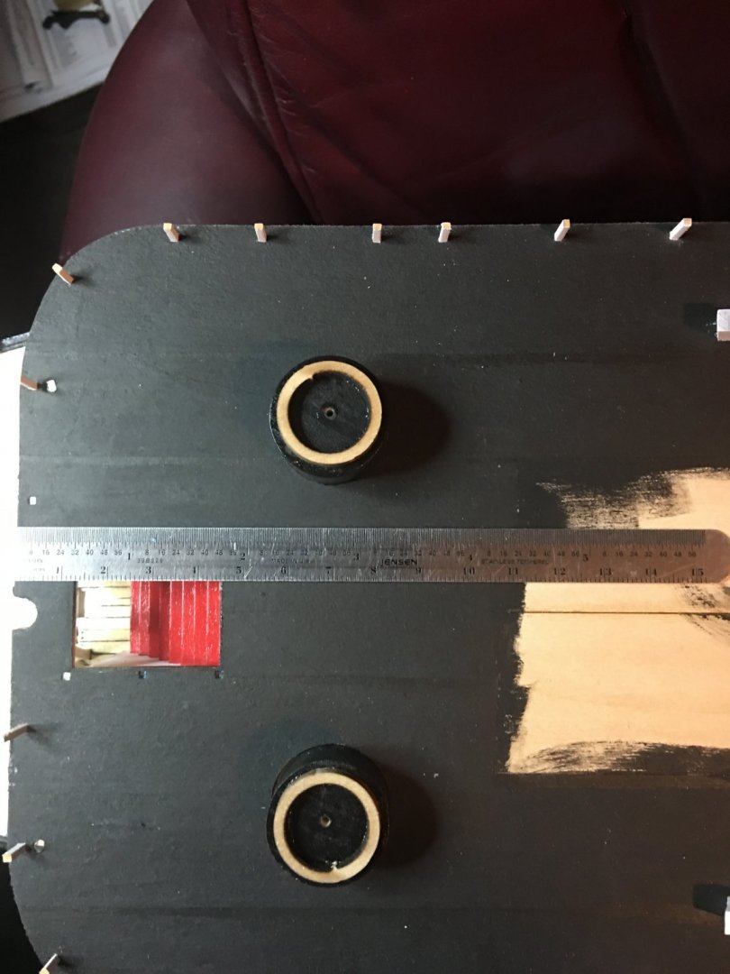
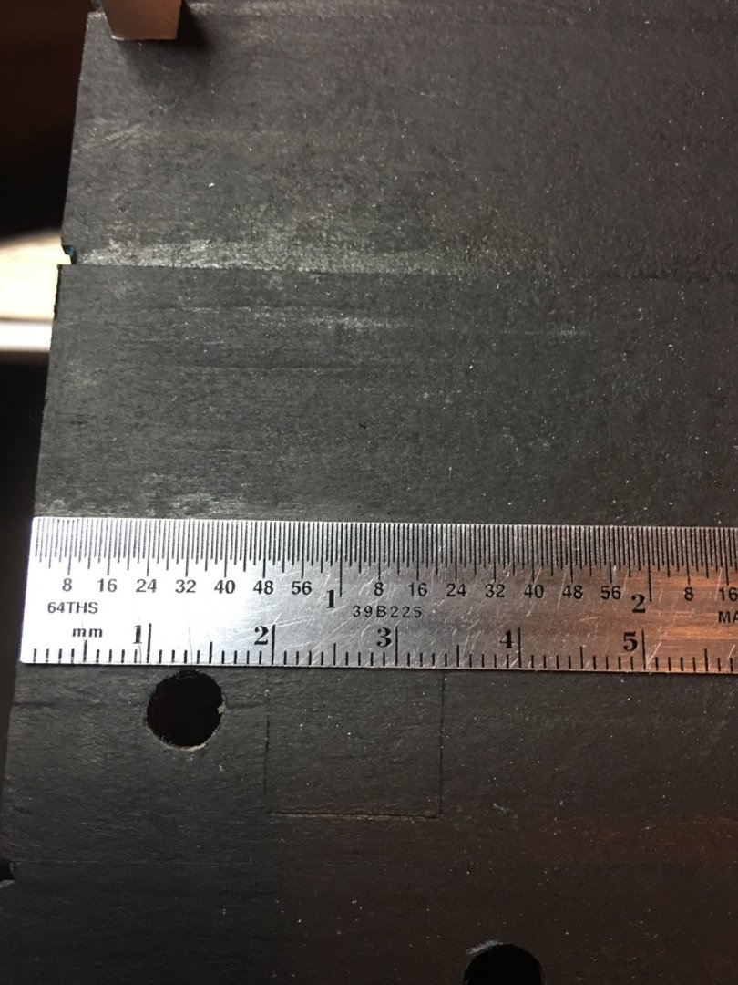
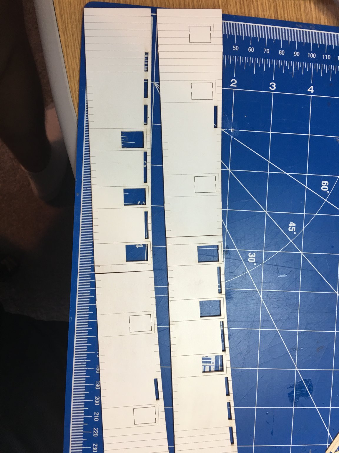
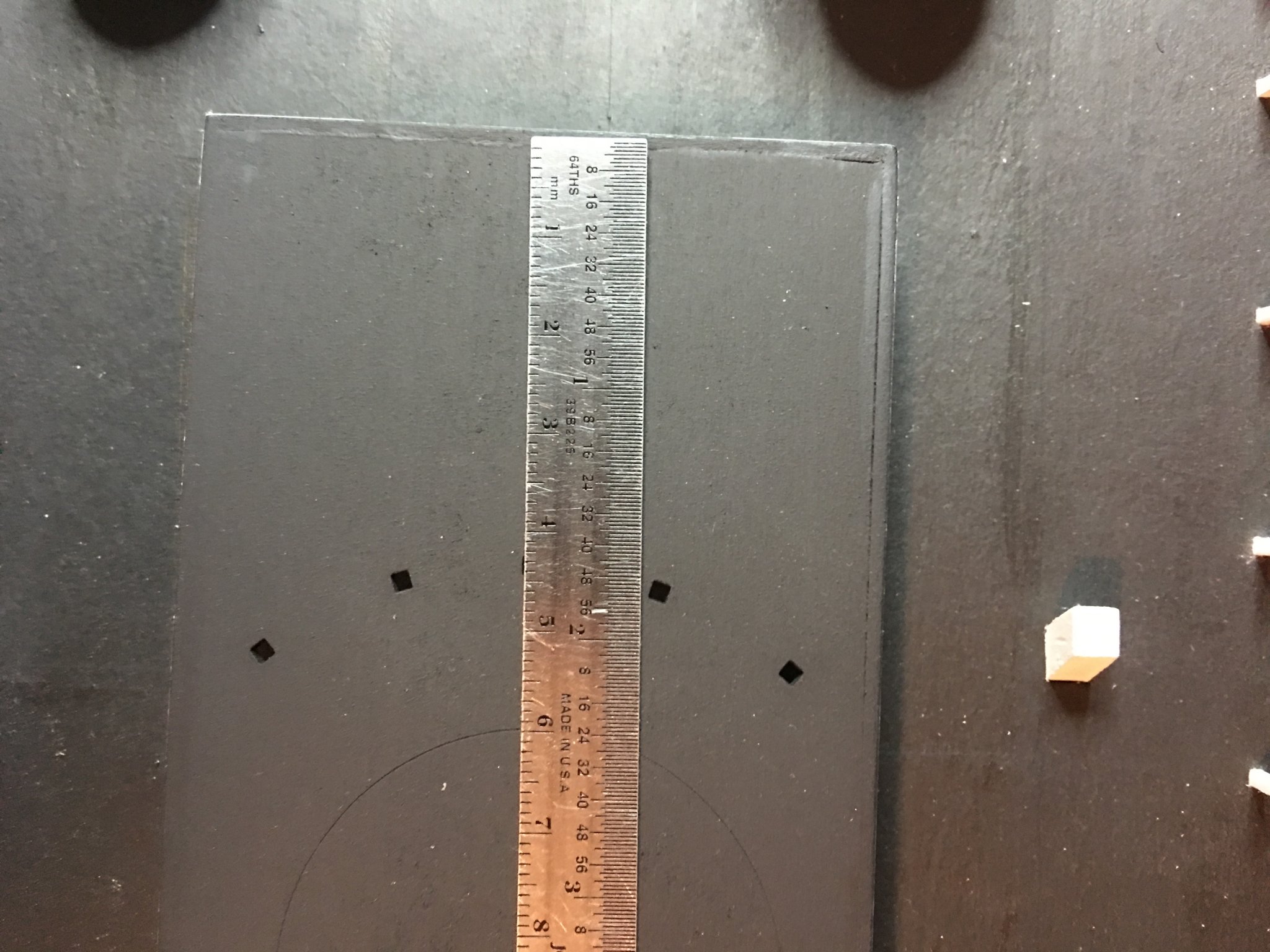
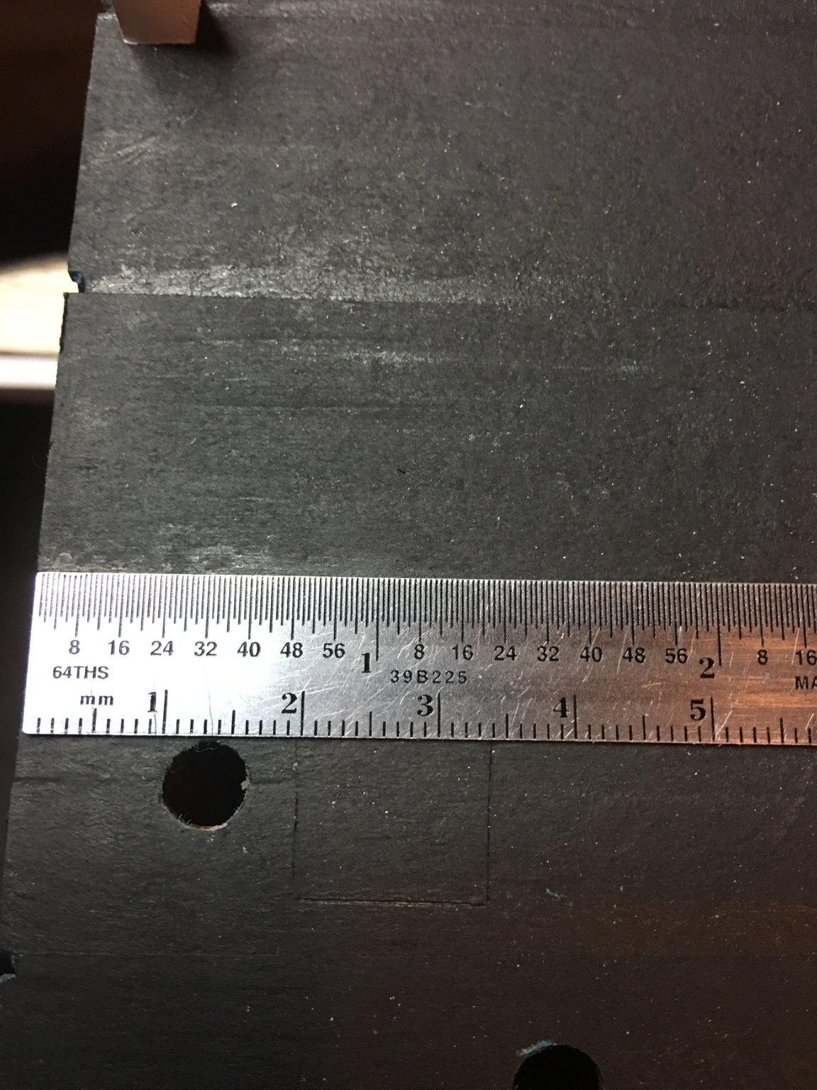
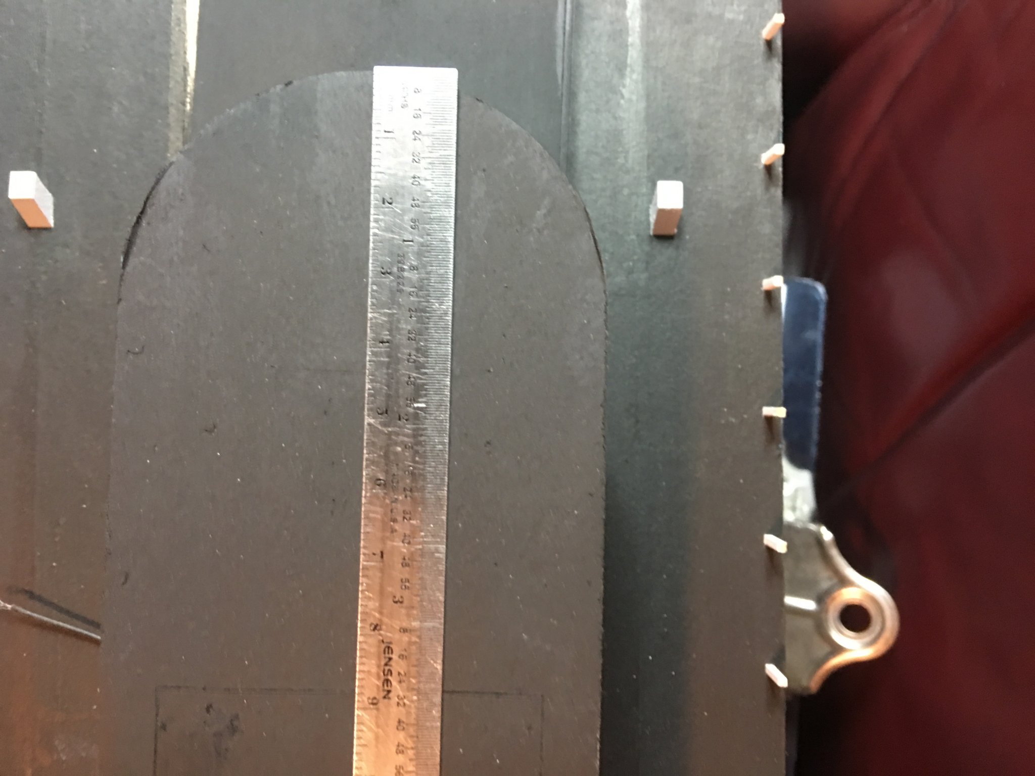
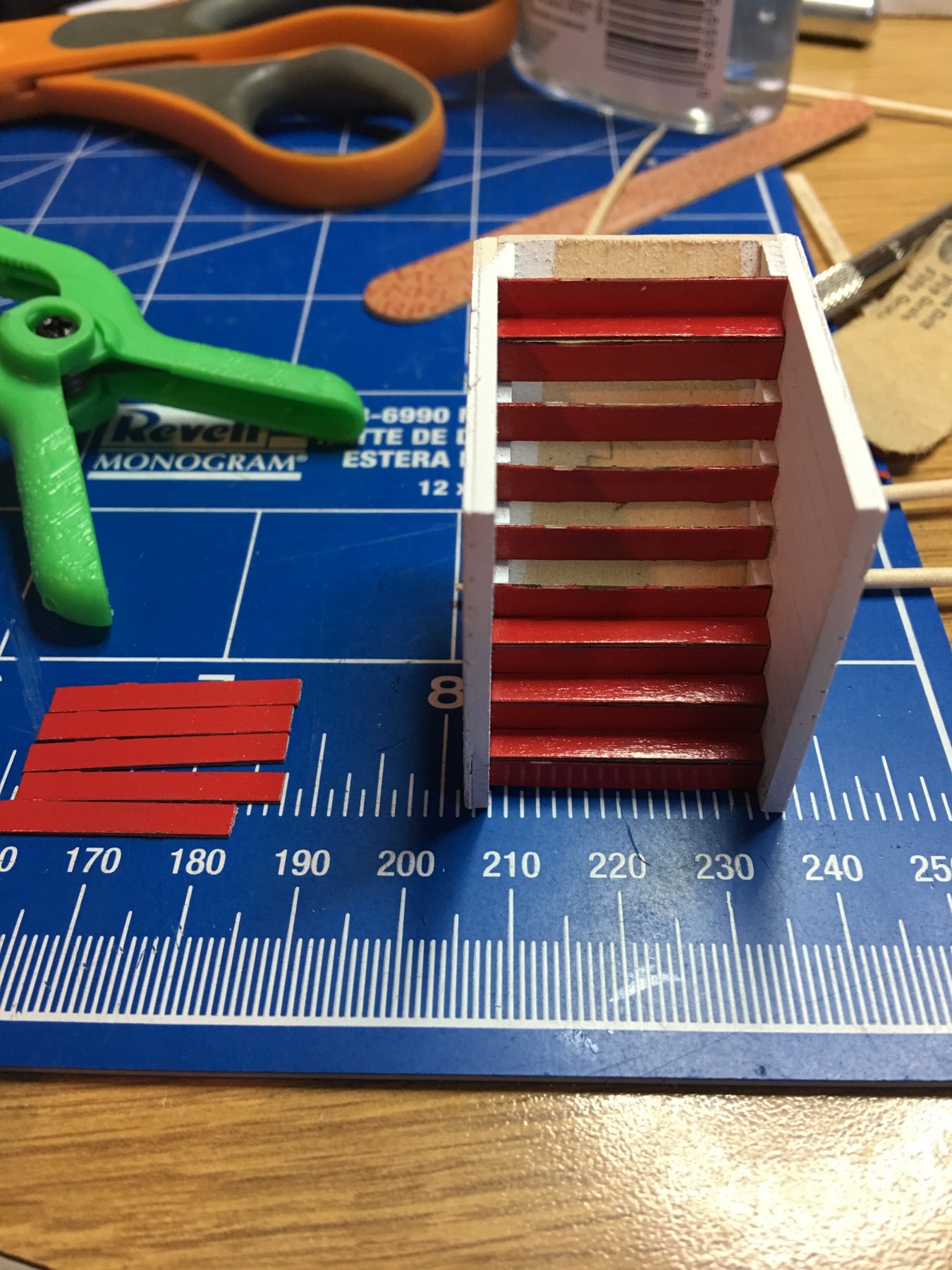
Here are a few photos with a ruler for reference to help you out.
On the Boiler deck roof, the reference line for the Hurricane deck is 105mm from the front edge.
On the hurricane deck the reference line for the Texas deck is about 60mm from the front edge, this is including the trim.

The chicken coop line is 20mm to 34mm from the aft edge of the Boiler deck roof.
And for the pilot house lines on the Texas deck roof the reference lines are 88mm from the front edge.
Sure hope this helps.
-Brian
-
Greetings all,
I figured it was time for another update. Things have been going at a snails pace lately due to being down an arm, but therapy has started and the road to getting back to normal is close. In the meantime, here is what I have been able to accomplish.
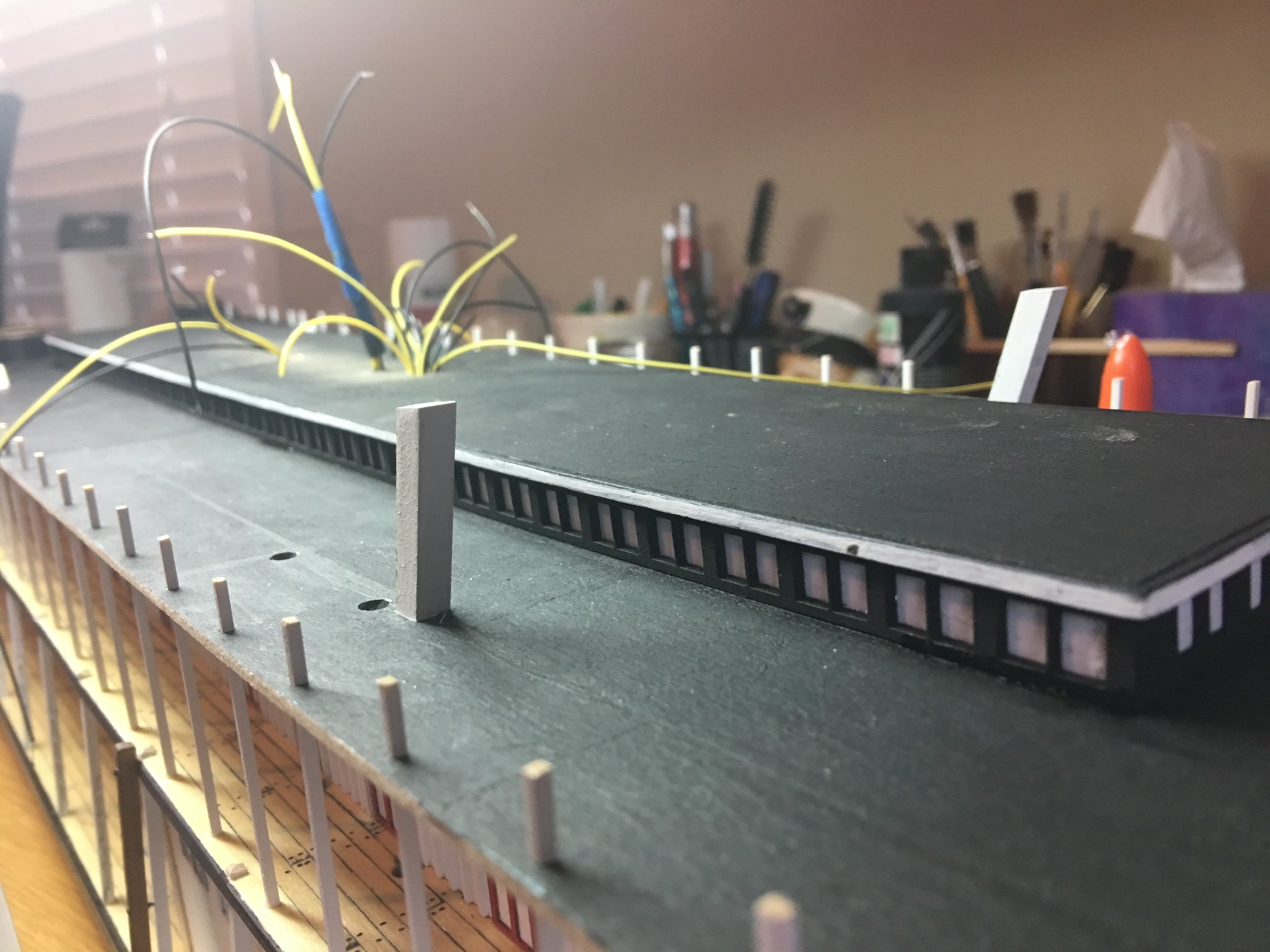
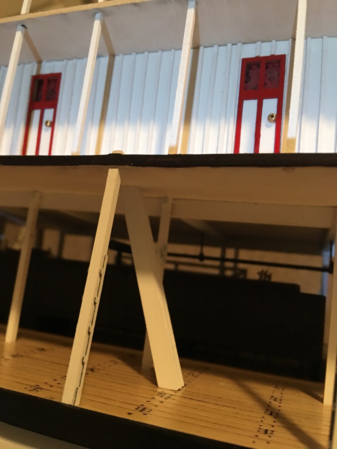
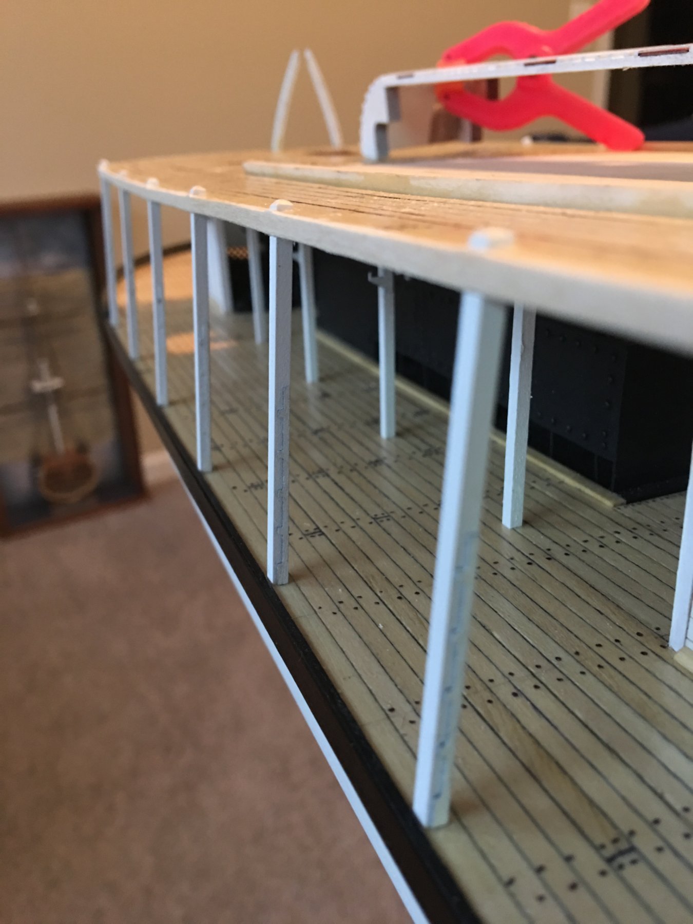
On my last update I was working on finishing the boiler deck. I finished installing the stanchions and the hog truss posts. I went the extra step and installed the forward Hog Truss all the way from the top of the boiler deck to the main deck. This omission has been mentioned in several build logs and I made it a point that I wasn't leaving it out. The toughest part of this was getting it lined up and matching the angle. But somehow I managed.

When installing the stanchions, I first set the bottoms in place and glued them down. After they were all set I cut several pieces of scrap wood to length that matched the height of the boiler deck walls. Then one by one I either clamped them down or spread them apart to get the stanchions all set to the right height.
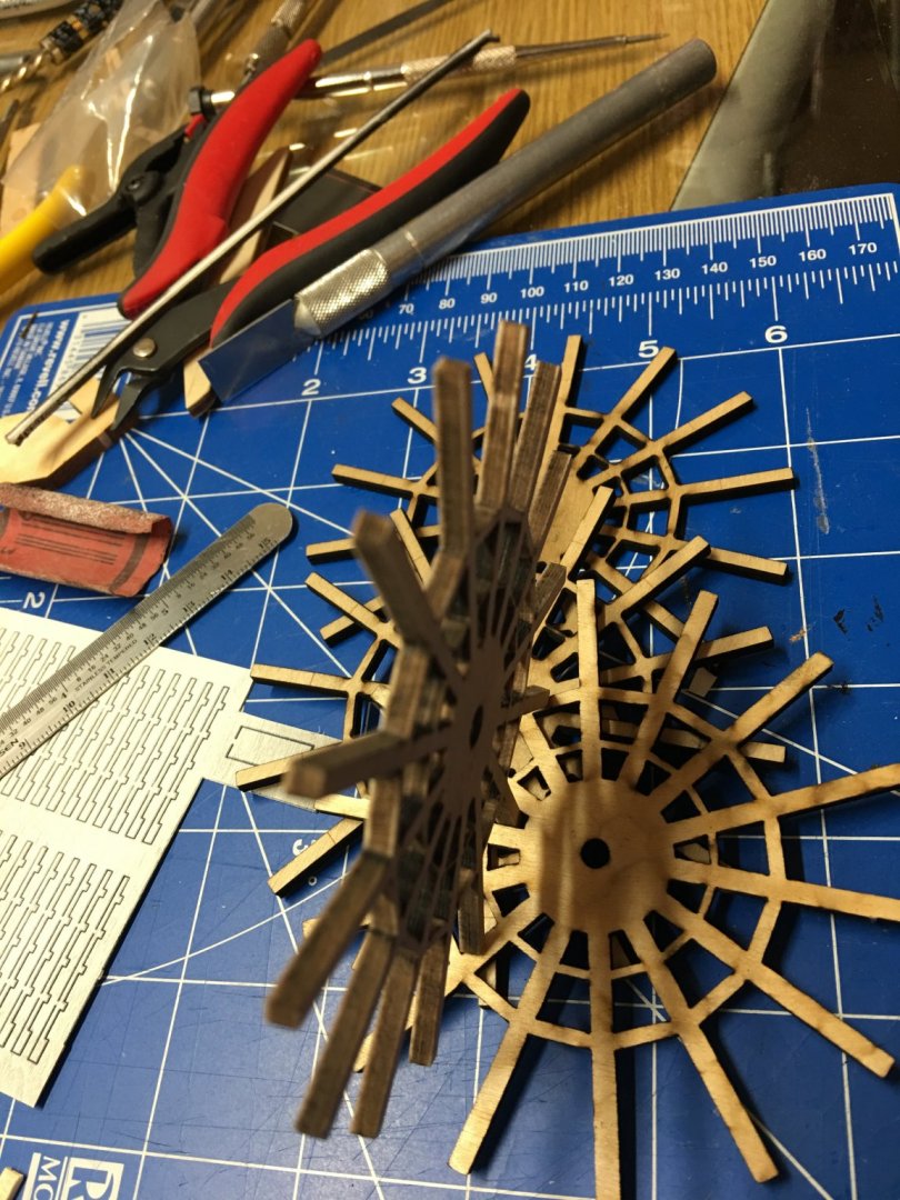
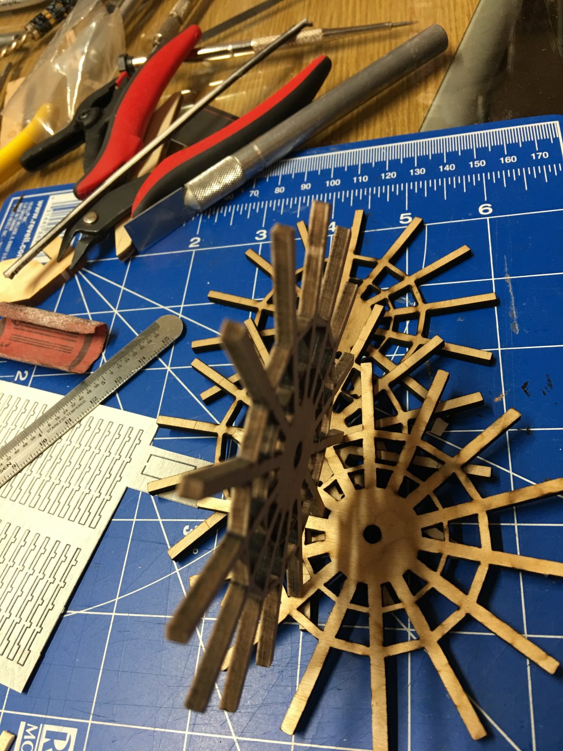
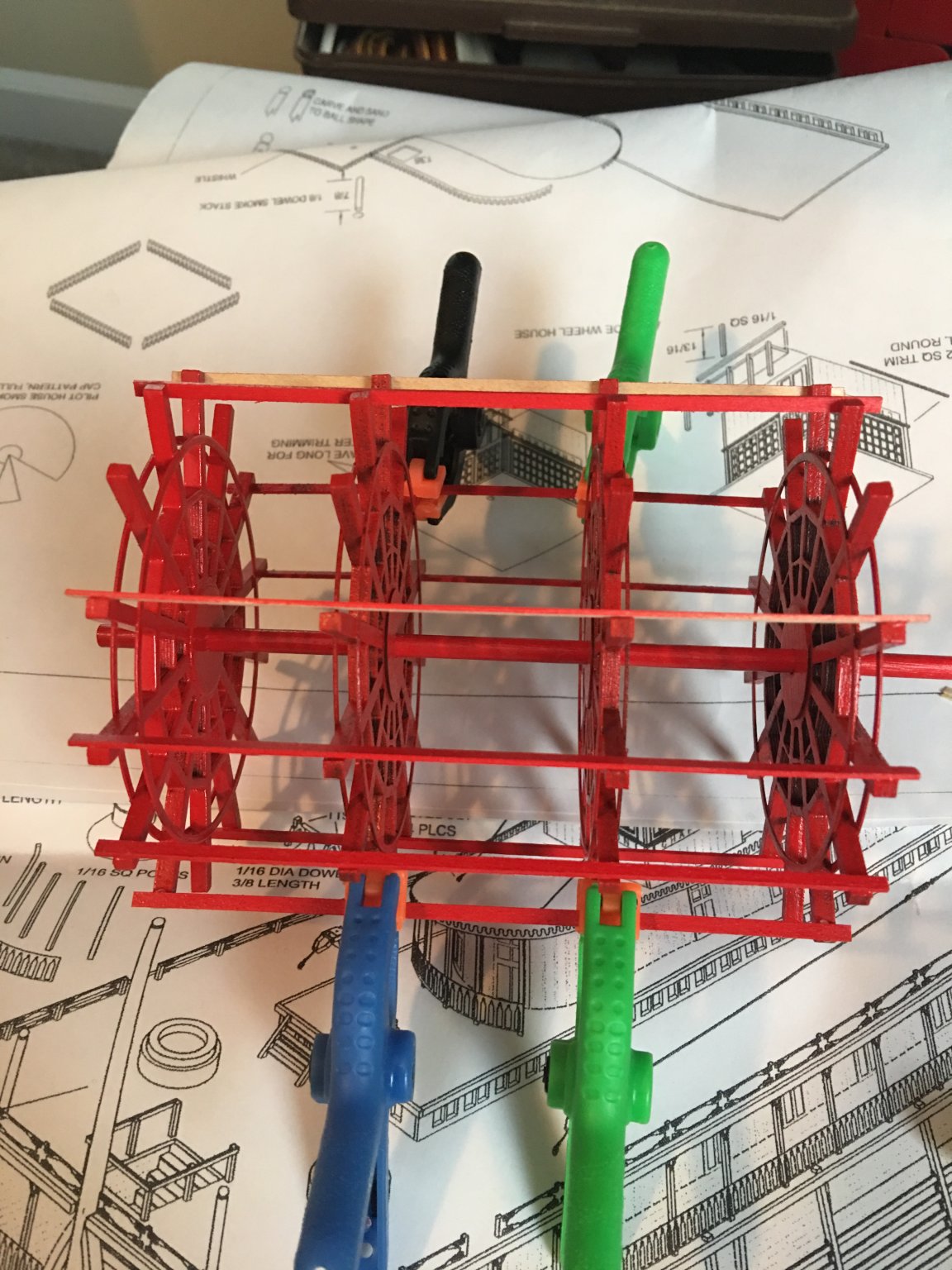
With all of that completed, I decided to tackle the paddle wheel. This task in itself is another fine, time consuming build.
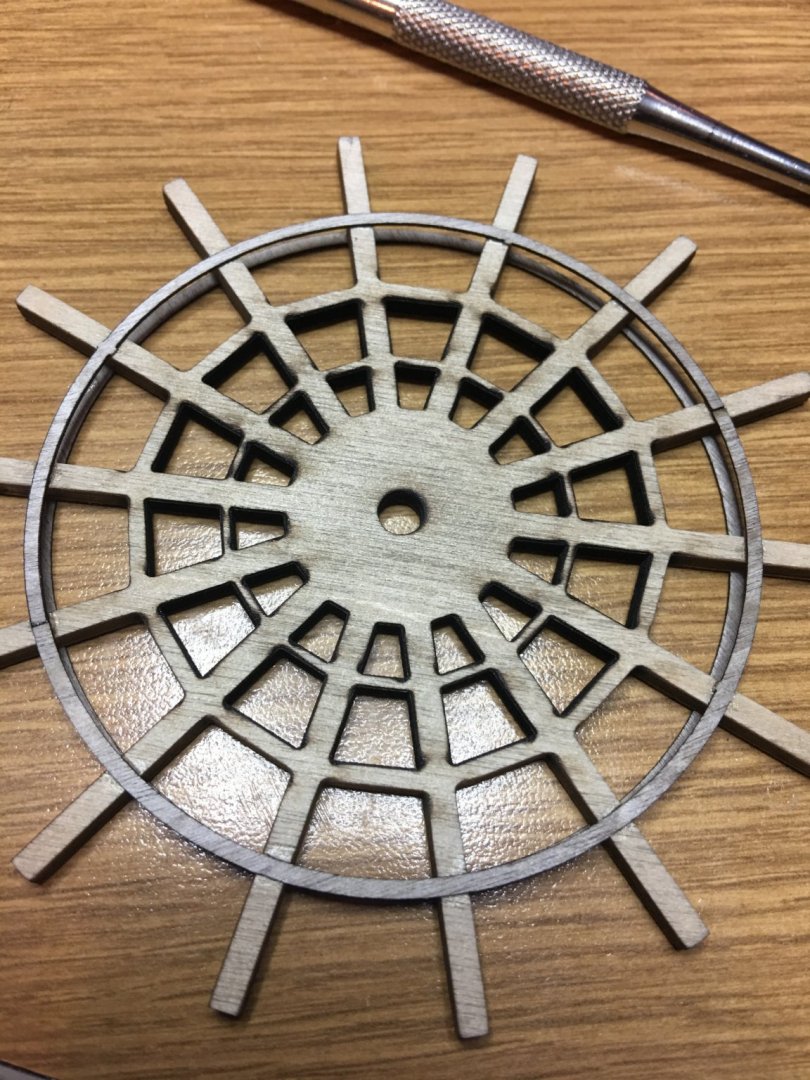
First thing I had to to do was to remove the char from the tiny little crevices between all the wheel spokes. Of all the pieces of the model, I believe this part had the most char on it.
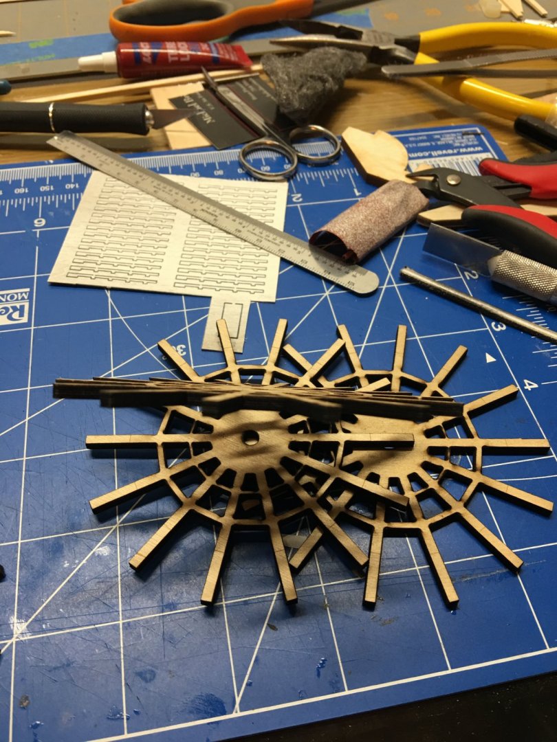
Cleaned and ready for building.
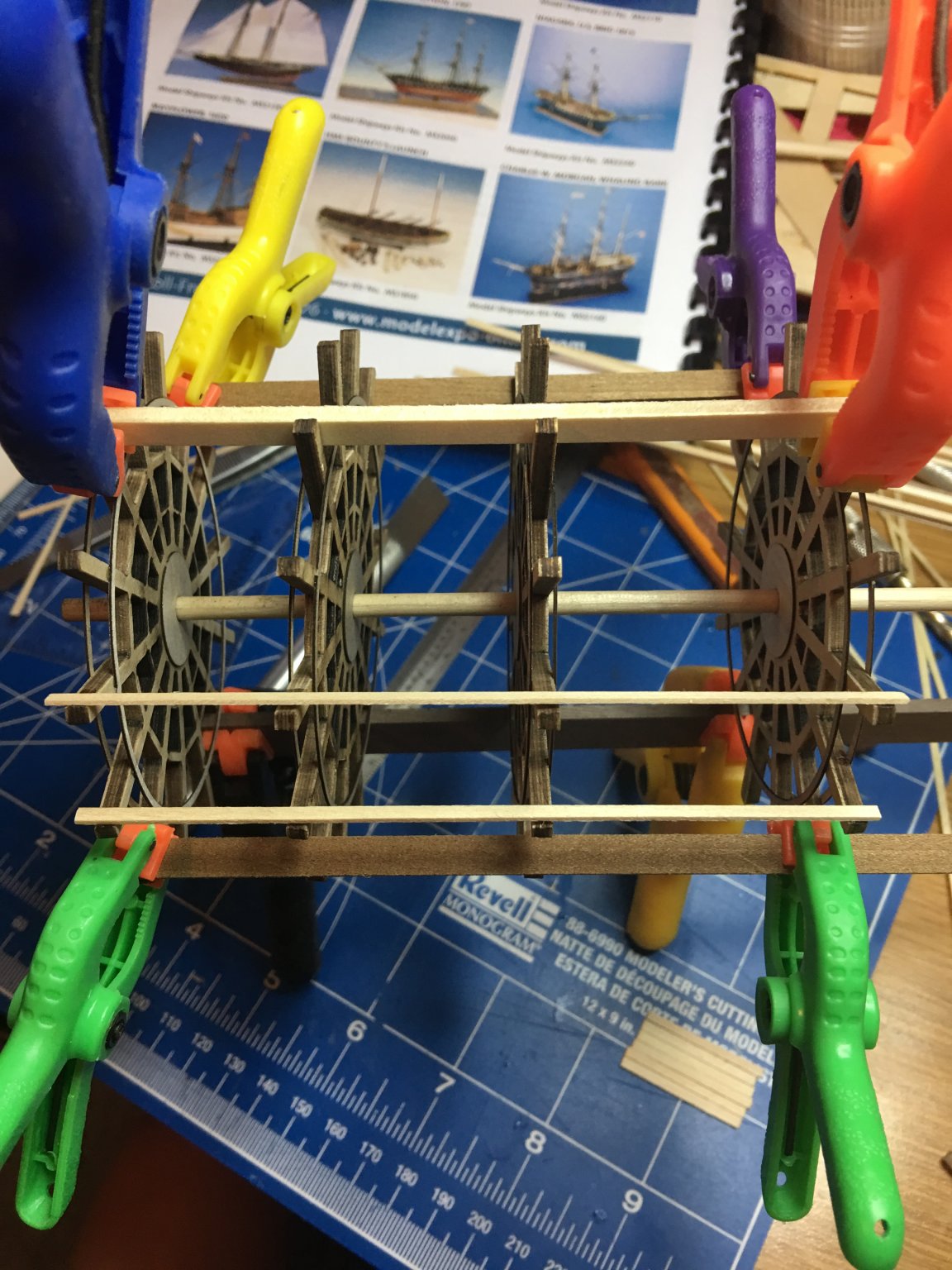
Installation of the outer braces.
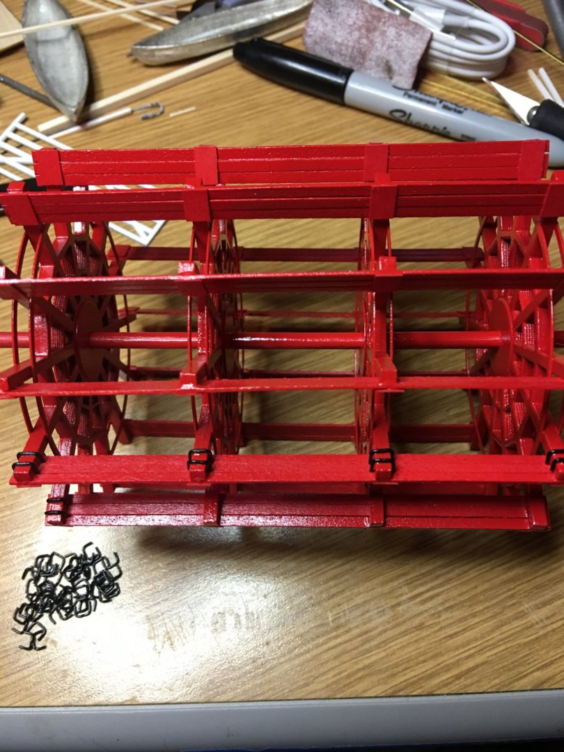
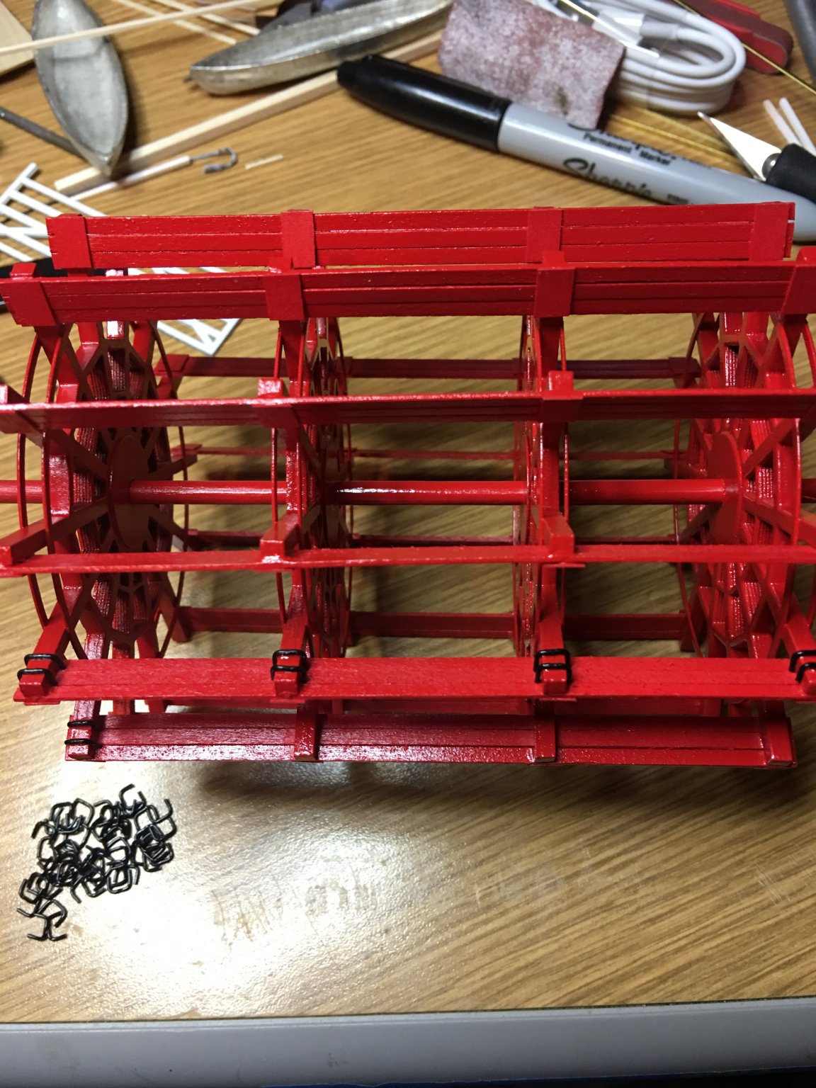
One of the more challenging parts was getting the spokes between wheels aligned and the wheels equally spaced. But with several clamps and some scrap wood, it all came together.

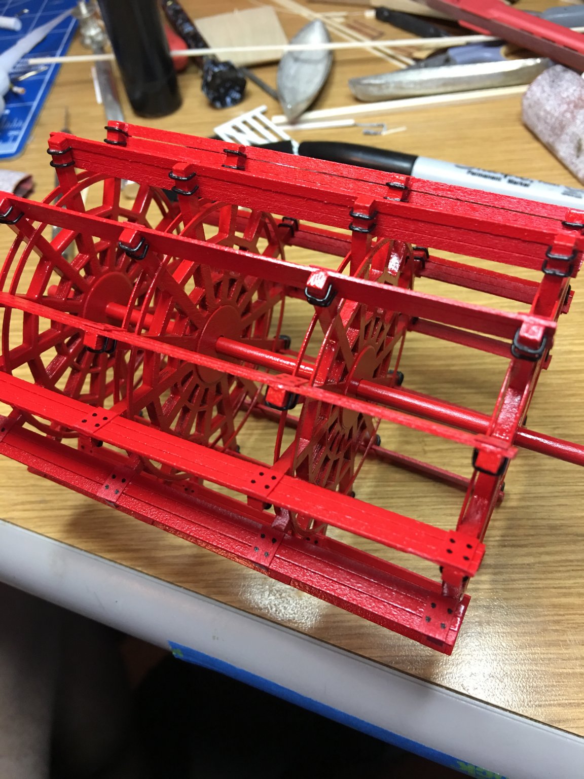
Once the wheels were aligned and spaced, then came the paddle boards. I went with the three thinner boards as suggested in the instructions because I liked the look of them and I wanted to add the extra detail of the u-bolt brackets and support boards to them.

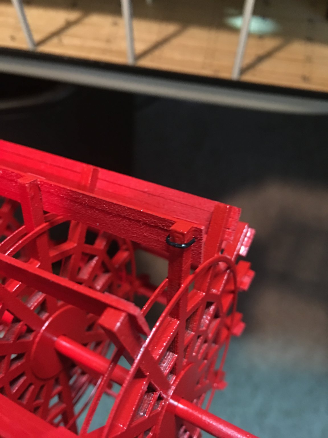
The came the tedious part of the paddle wheel build. Cutting and installing the 108 tiny u-bolts. For these I used black plastic coated 20ga wire. I wrapped the wire around a small scrap of wood leftover from the paddle wheels. This gave me the correct width to fit snugly against each spoke. I then took each u-bolt and with another scrap of wood sanded to the correct thickness of the spokes, trimmed each one to length.
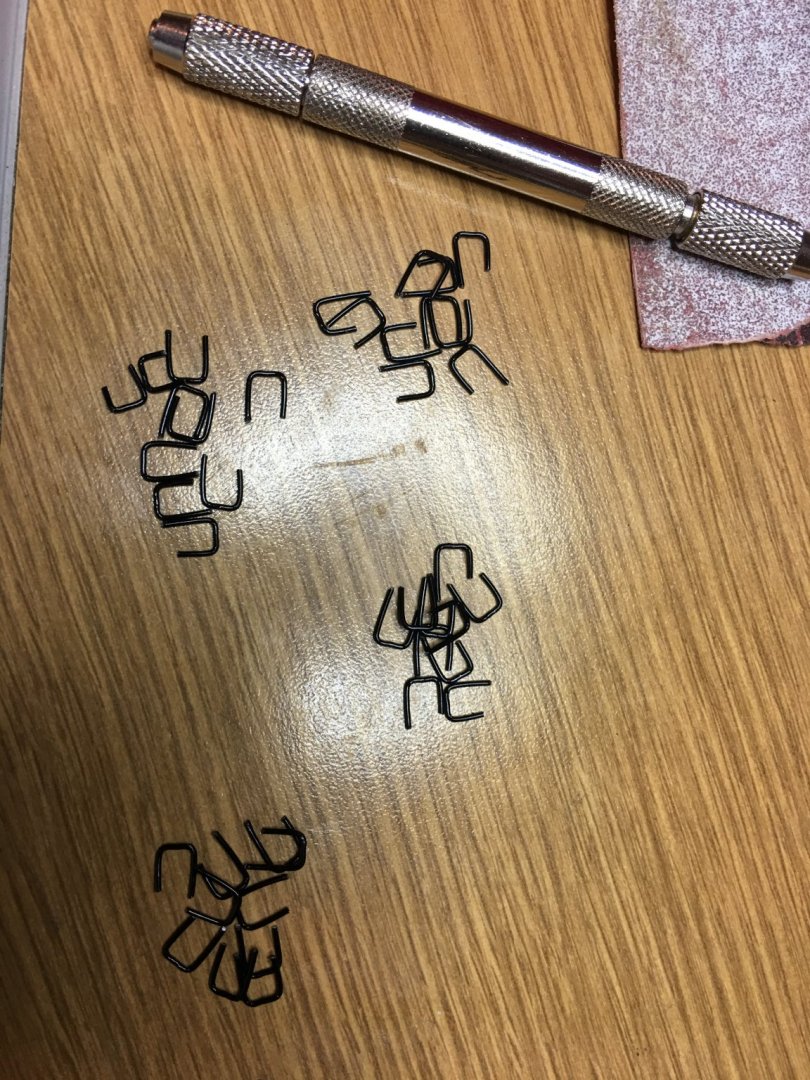
....then the tediousness began.

I don't know what it is about this angle, or if it is a trick of the camera, but the paddle boards look way out of whack. I promise you though they are all in line with the central shaft. They say the camera adds ten pounds, well in this case it skews things all wonky. Then again, you can't expect much from a phone camera and I have never claimed to be a professional photographer.
Several days later, I finally had the finished product. I went ahead and simulated the bolt heads on the paddle board side with a fine point sharpie. Nothing I had on hand seemed to work for these to give it a more three dimensional effect, so I just went the easiest route. I think it came out looking pretty good.
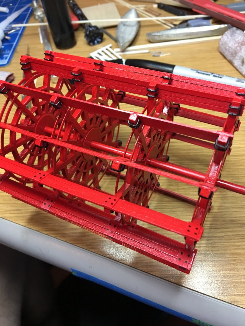
With the stanchions in place, the boiler deck roof "tar papered", this is where she sits as of today. For now I am going to wait until later to install the paddle wheel. Just one more thing to get in the way. I need focus more on getting the Hurricane deck (or as the instructions call it, the skylight) painted, windows installed and LED's in place, then start on the Texas deck. I'm having a hard time trying to decide which task was more monotonous, the u-bolts or the battens on the boiler deck. I'll let you know what I decide once I've completed the Texas deck. I think I have a few hundred more battens that need to be installed there.

Anyway, I appreciate all the "Likes" and kind comments, and as always, thank you for looking.
-Brian
-
Eric,
She's really becoming a beautiful model.
I am by no means an expert on steamboats. Most of what I know I have learned from you, Kurt and many others in the discussions on this forum. However, during my reading of some of these builds, just about all of which you have contributed to in some sort of fashion, there have been many a discussion on the paddle wheel box size. All of which bring up great arguments for the differences in the sizes of the paddle boxes.
In Greg's build of the Heroine around post #544 there is an in depth discussion of the size of her paddle boxes in relation to the size of her paddle wheel. One of your comments in this build was the possibility the extra room was to allow for any debris picked up by the paddle wheel to pass through without causing too much destruction to the housings or as Bob said earlier (post # 342), the extra room could have been built in for ease of river maintenance. All good reasons for the over sizing of the paddle box.
On the other hand, as Bob also stated, would the owners have gone though the added expense to make them over sized and would they have built them so wide as to block passage from fore to aft as you stated. I know these were not luxury liners, but accommodations could have been made for the ease of paying customers to walk the length of the boat without having to go between decks to get there.
Even after studying the excavation pictures above there is truly no definitive answer other than the superstructure supporting the paddle wheels could have been used for the upper decks support as well as the support for the top of the paddle boxes. For what it's worth, my two cents is that I tend to believe that the paddle boxes on Arabia would have not been too much wider than the paddle wheels. Their inboard walls would have fell in line with the superstructure supports of the paddle wheels and that room would have been provided for passengers and crew to pass between the walls of the paddle box and the boiler deck walls.
I know this isn't much help with your conundrum, but either way you decide to build her I'm sure she will come out looking outstanding.
-Brian
-
-
Mtaylor,
Truly interesting story. I would have never guessed that’s how it got it’s name. By those same facts, I guess if they run out of names for the larger cabin decks in the future, the Alaska deck is next in line.😀
Eric,
I’ve read stories on the Heroine and have wanted to visit the wreck site since it’s only about an hour drive from me. Just haven’t had the time lately, but it is on my to do list. In all actuality, I’m only two miles from the Red River although where I’m at it is currently a channel under Lake Texoma. The Dennison Dam about 25 miles east of me is pretty much the beginning of any real navigable part of the river these days (no navigation locks to get past it t) Most parts west of the lake are wide, shallow, muddy streams. Not much a shallow draft steamboat couldn’t handle back then though.
-Brian
-
I agree. Just one of those head scratchers that pops into my thoughts while toiling away in the shipyard.
I get the main deck name, since it is the main point of entry to the boat. The boiler deck sits above the boilers (in most cases) so I can see that one to.
Just the hurricane one one struck me as funny.
...and don’t get me started on my thoughts of how they came up with the Texas deck. I don’t think there is a river big enough in this state to support a steamboat. At least one that was around during this era.
Just random thoughts.
-Brian
- Canute, Cathead, GrandpaPhil and 1 other
-
4
-
Eric,
I'm loving your Pilot House and Hurricane deck build. She's just about topped out. The pilot house was one of my favorite parts of my Chaperon build. The model kit left me with a blank slate to do with as I please so I took full advantage of it.
I often wonder why they call it a hurricane deck though. As on the Chaperon, it's not really much of a deck but rather a nice source of natural lighting for the boiler deck.
...and I definitely wouldn't want to be on board a steamboat in a Hurricane. JS
-Brian
-
Howdy Everyone,
It's been a while since I have had any updates. Unfortunately, some of the rough treatment of my body as a youngster has finally caught up with me. I had to have shoulder surgery which has put me out of commission for some time. Kinda hard to work on tedious details with one arm. Any how, I still didn't let me keep me totally out of the shipyard but it did keep the work to a minimum.
First thing I need to do is apologize for a couple of errors that I made on my last update. I had accidentally stumbled across the UoW LaCross Steamboat website, but as I read in more detail of Kurt's Chaperon build article, I noticed that he had mentioned this site in this article and I either overlooked it in reading or just read it and completely forgot about it. I just want to make sure that credit goes to where it belongs.
Secondly, I had added the fenders to the main deck stationaries from a photo I had found on the above mentioned UoW LaCross website, thinking it was an omission on the kit. After looking more carefully, the fenders are actually included. I really need to pay more attention to details.
Now that I have that out of the way, time for some progress updates.
I tried picking a few sections that would enable me to work with one had so I did some work on the stage, Hurricane deck and some boiler deck details.
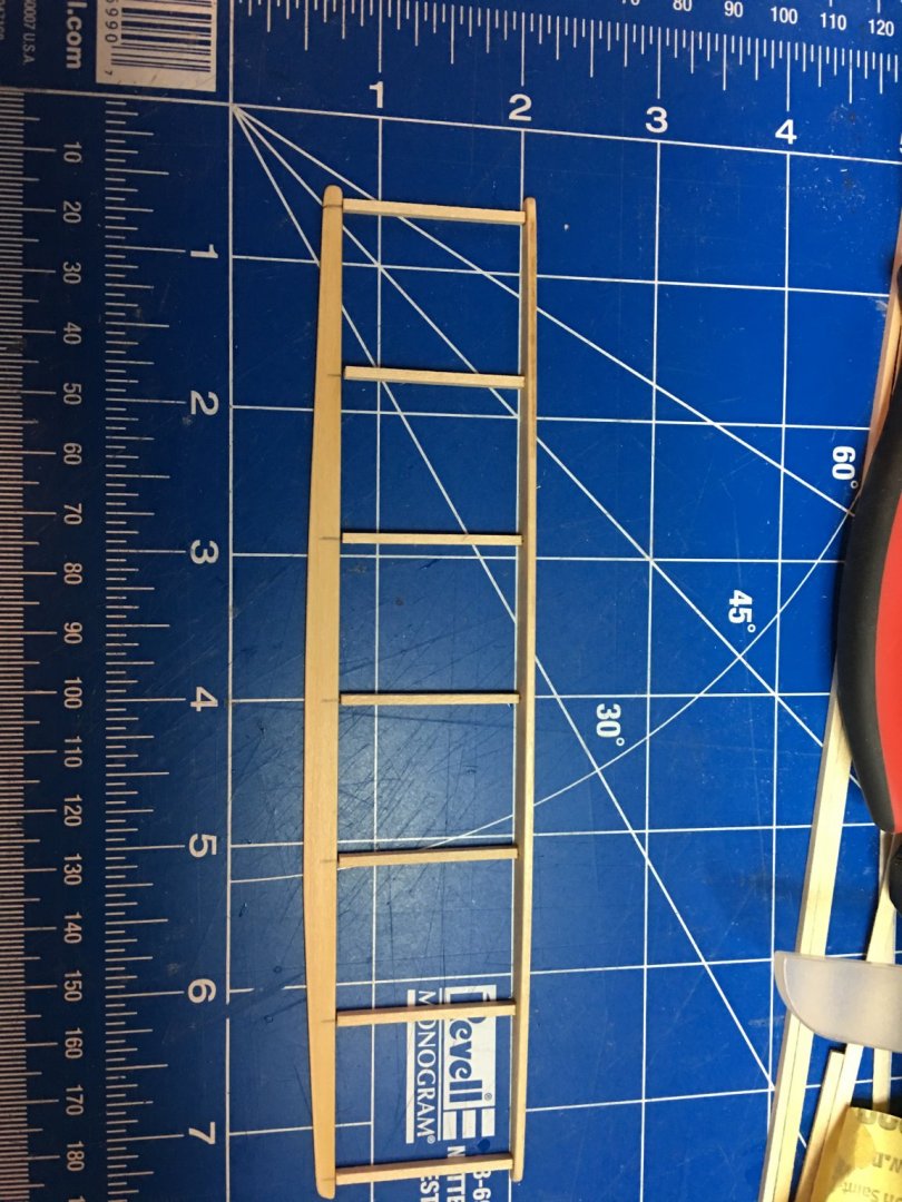
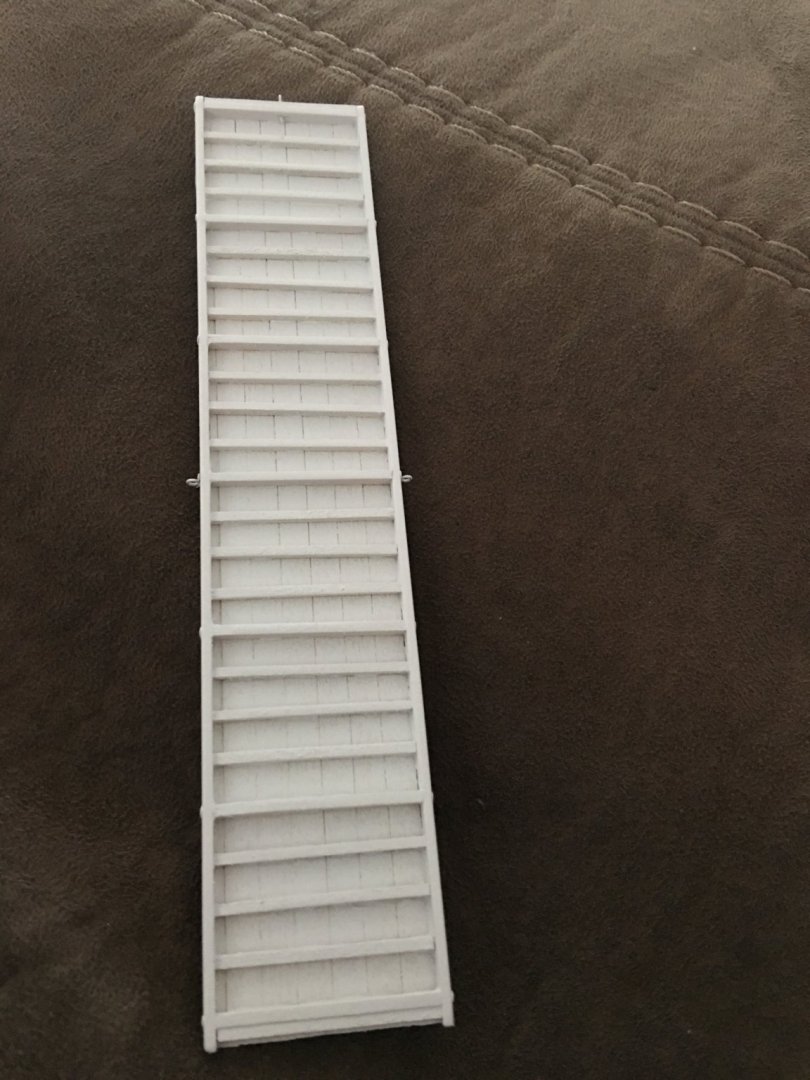
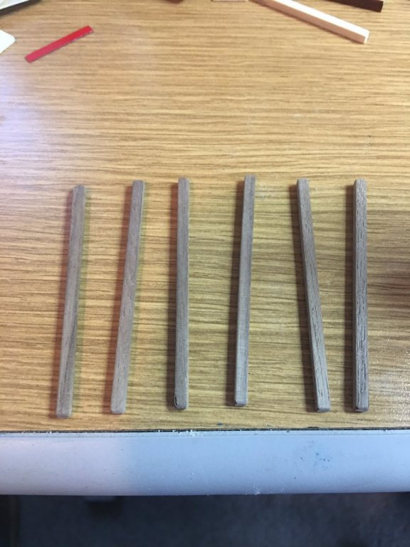
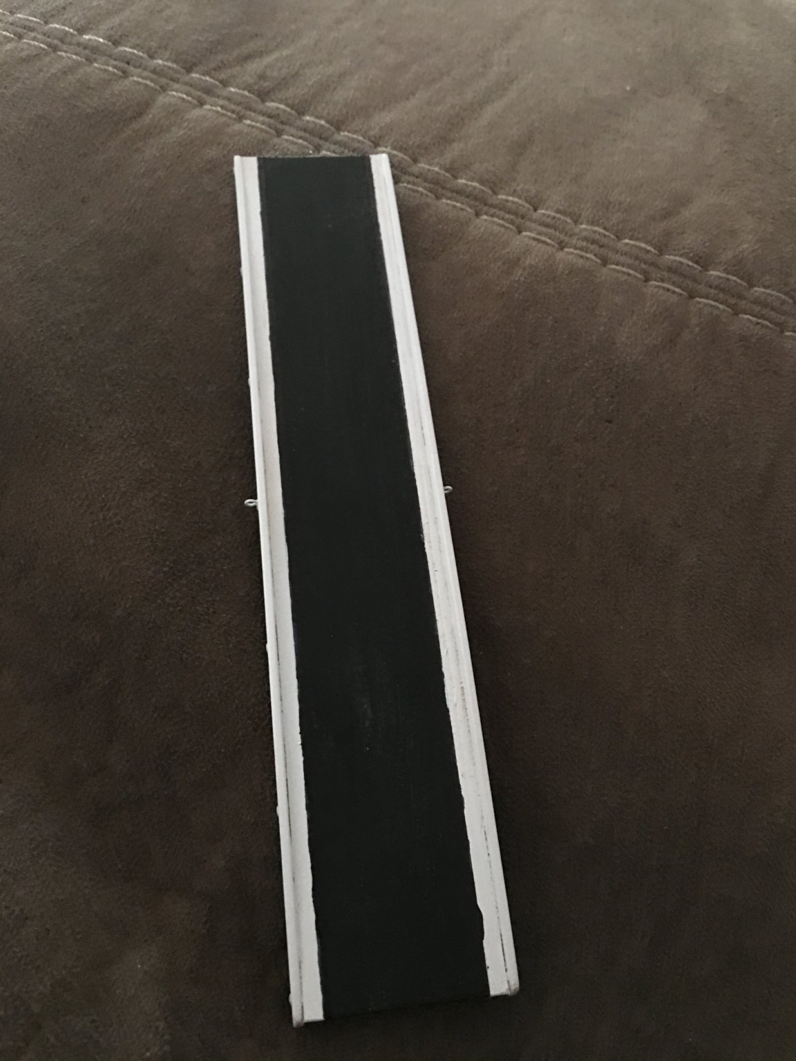
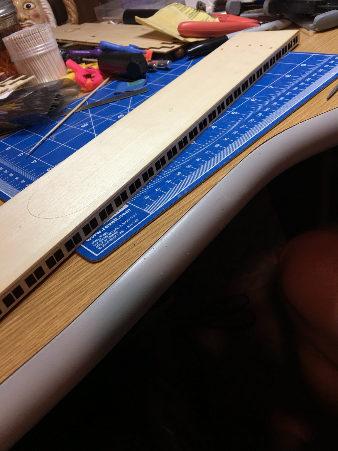
The details in the construction of the stage were a little lacking, especially in comparison to the actual boat. The LaCross website had a great photo showing the details of the underside construction of the stage, showing cross braces along with the planking.
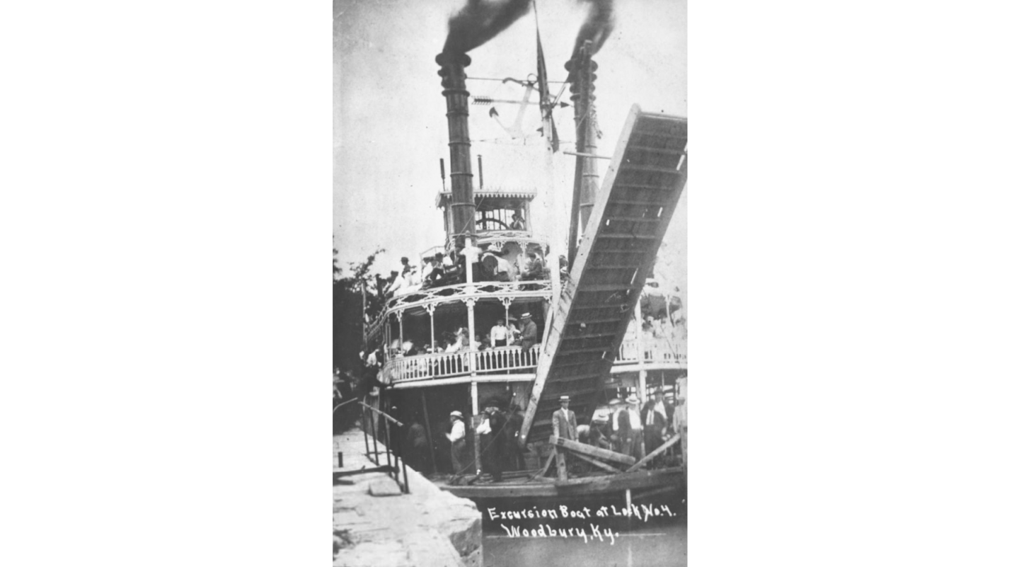
The model plans call for 20 - 1/16" x 1/8" planks glued together along with the side braces. If I were to construct the ramp according to the plans and add the cross bracing the entire structure would be too thick for the side braces to cover it all and look correct.
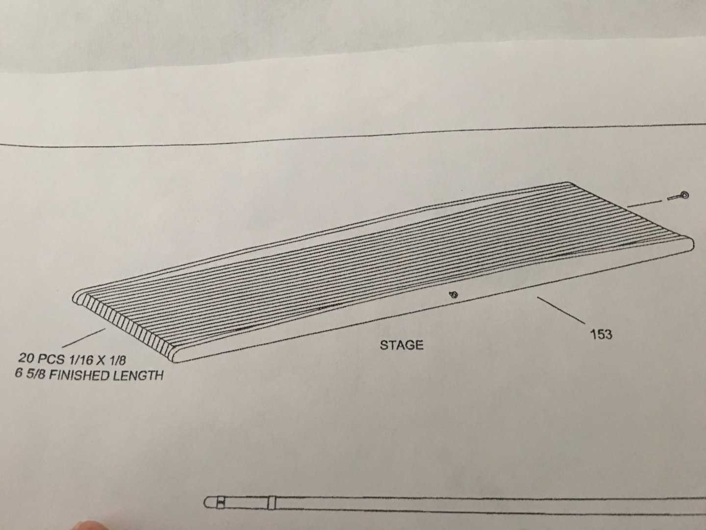
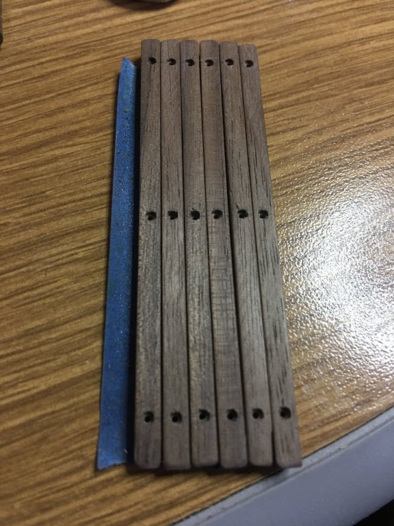
So I improvised and made my own version making the cross bracing and using thinner planking for the decking. If you look close on the old photo, there look to be two thicknesses of cross braces. The thick ones seem to be bolted through the side brace, with three intermediate braces that seem to be a little thinner. So this is what I came up with.
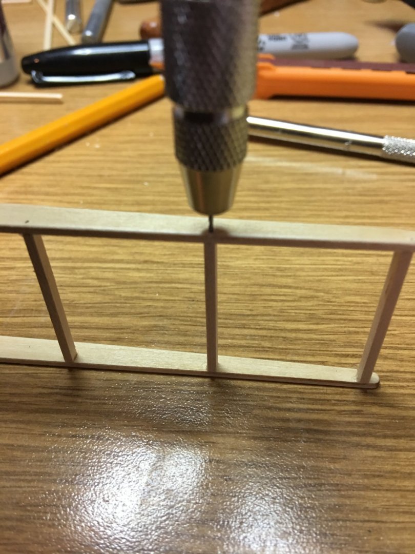
Framing thick cross braces between the side braces and dry fitting them.
Pilot holes drilled and brass nails inserted to simulate the bolts.
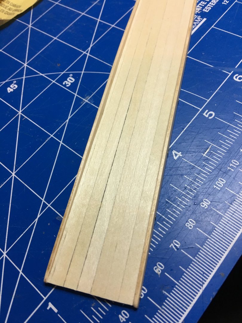
Leftover deck planking used for the decking.
Using some silkspan and black paint I created the non-slip walk way.
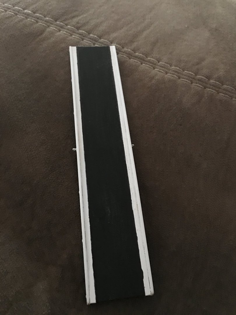
Final underside after painting.
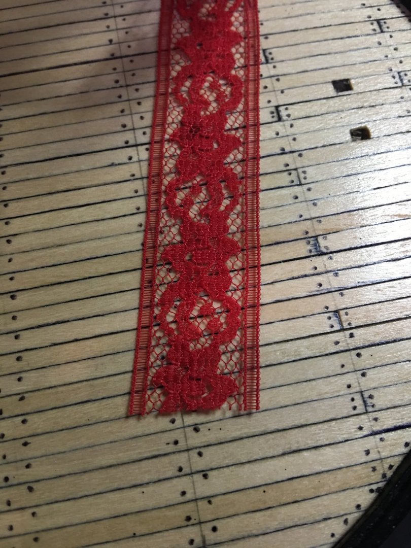
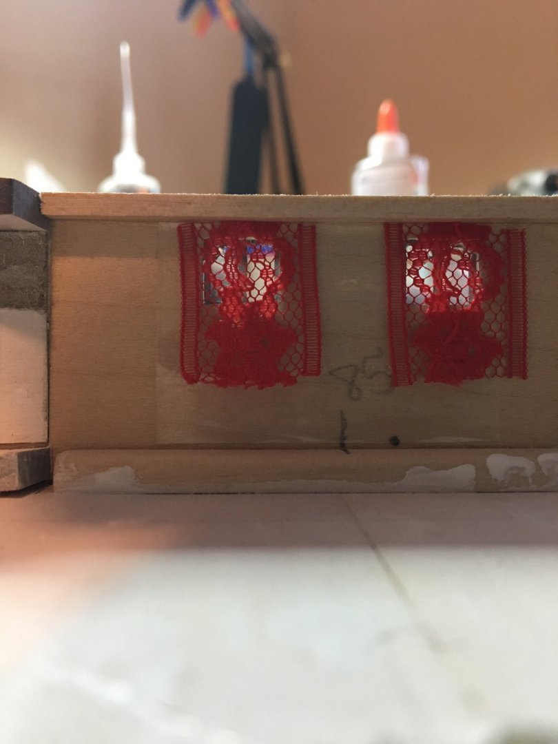
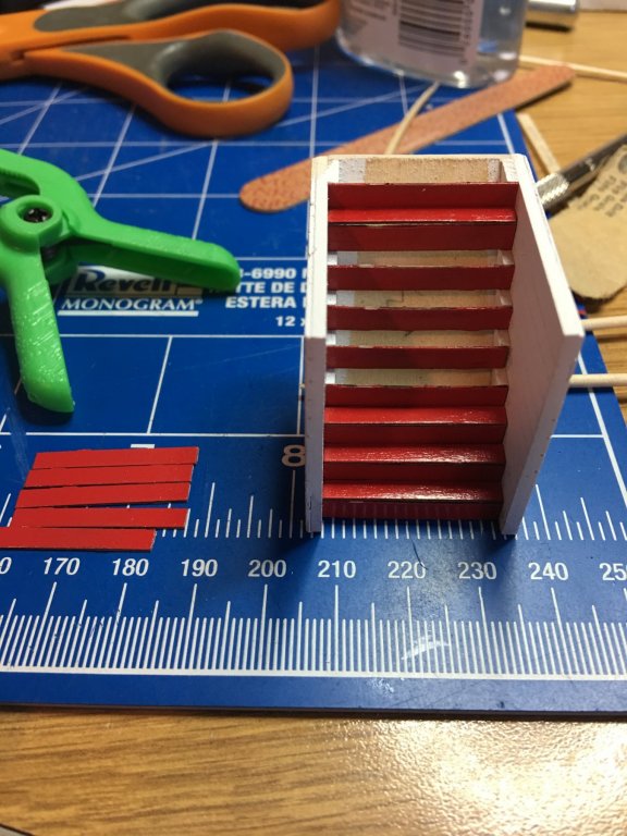
Next I did a little detail work on the inside of the Boiler deck staterooms. Using a little lace that I "borrowed" from the Admiral's sewing machine, I created some curtains to decorate things up a bit.
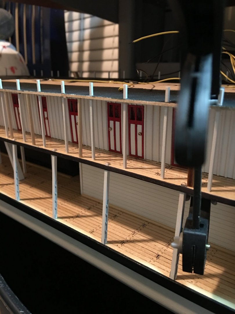
Finally, I started work on the Hurricane deck construction and placing the decking on the boiler deck.
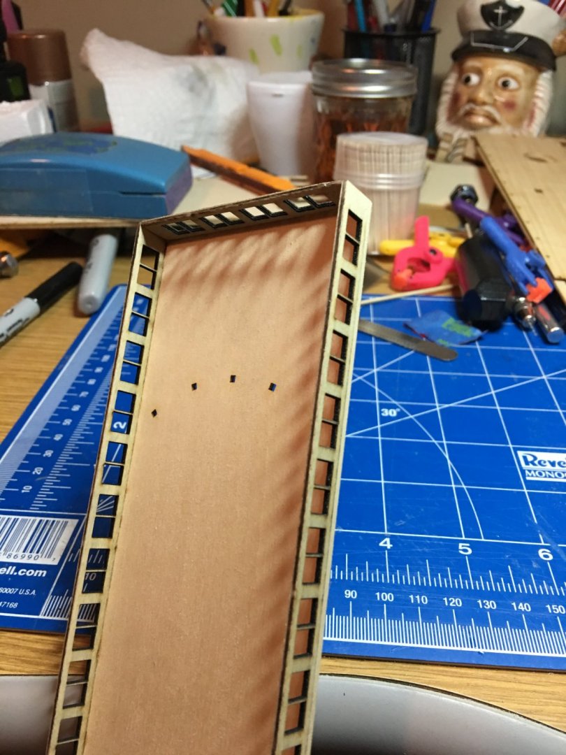
And this is where she currently sits. A few more LED's added for the eventual deck lighting.
As always, thank you for stopping by a looking.
-Brian
- cog, Captain Poison, Canute and 3 others
-
6
-
Tom,
I'm in the process of building my Chaperon and love the direction you have taken her. Nothing like reading a good yarn.
I'll sit back a keep an eye on your build with extreme interest.
-Brian
-
Eric,
Beautiful chest. We are surrounded by cedar trees and have an overabundance of them on our property. I have often though about purchasing a sawmill and harvesting some of the timber for closet lining and other misc projects that the Admiral can come up with, just haven't had the opportunity.
Your Arabia, is really starting to take shape. It won't be too long before the winter drives you inside and you can dedicate more time to her. I know I'm looking forward to cooler weather. Nothing like spending a cold day in the shipyard, throwing a football game on the TV and kicking back making sawdust.
BTW: Thank you for the great link on the newspapers. All sorts of interesting stories.
-Brian
- popeye the sailor, mtaylor and Canute
-
3
-
On 8/17/2019 at 11:24 AM, Cathead said:
Great work! Love the added bumpers, they're definitely a realistic touch.
Regarding Cairo, have you looked at BlueJacket's kit? It's mostly wood (you can view a kit-contents video at that link). I'm strongly considering that as my next project. Also, there's a fantastic large-scale build of the USS St. Louis (a sister ship to Cairo) being build by the Gateway Model Shipcrafters club in St. Louis. As far as I know they're relying heavily on Cairo plans, so you could contact them for advice and resources. I suggets reading their log as a reference; I've seen the in-progress model in person and it's amazing (and huge). They've been maintaining the log intermittently lately but I can put you in direct email contact if you want.
Regarding a sidewheeler prototype, there are certainly lots to choose from. I love that UW site as a resource; it's where I found the Mary McDonald photo collection I've been using as a reference for Arabia. I also have a copy of Way's Packet Directory, a nearly comprehensive listing of all known interior riverboats with varying levels of information on each one (history, dimensions, tonnage, masters, features, sale history, etc.), so I'd be happy look up any given craft for you.
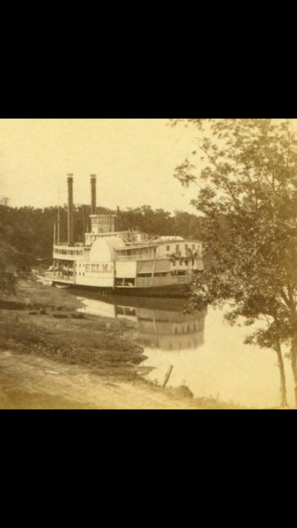
For example, there are three entries for sidewheelers named Selma. The first was built in 1845, served out of Mobile, AL, and was lost in a collision in 1850 (here's an 1846 newspaper clipping about her). The second was built in 1853 under a different name but was renamed in 1856, primarily serving out of New Orleans until being dismantled in 1860. The third was built in 1867 and also operated out of New Orleans (here's an 1868 sales notice from the New Orleans Times-Picayune). The latter two were roughly the size of Arabia while the first one was a little squirt about 1/3 the tonnage. I'd guess yours is the third one but hard to say without more info.
Eric,
I have seen the BlueJacket kit. It's a relatively nice kit, unfortunately it is a little small for what I'm looking for.
The USS St. Louis build is a beast. I wouldn't have anywhere to put something like, except maybe my pond. Although, building a ship on that large a scale would be an awesome treat. If only I had the time (and funding).
I'm looking to build something in the 1/48 size or just a little smaller like this one: http://www.modelshipbuilder.com/e107_plugins/forum/forum_viewtopic.php?5406.0 .
In reference to the Selma, the photograph that I found is circa 1868. It was in with a group of other pictures that were discovered in France that were taken by Dr. Emeric deNux when he visited Avoyelles Parish, LA in 1868. I would have to agree with you on it being the third one since the other two were either destroyed or dismantled before then. So whatever information you have on this one, please feel free to pass along. I'd love to know more about her.
-Brian
-
Good morning everyone,
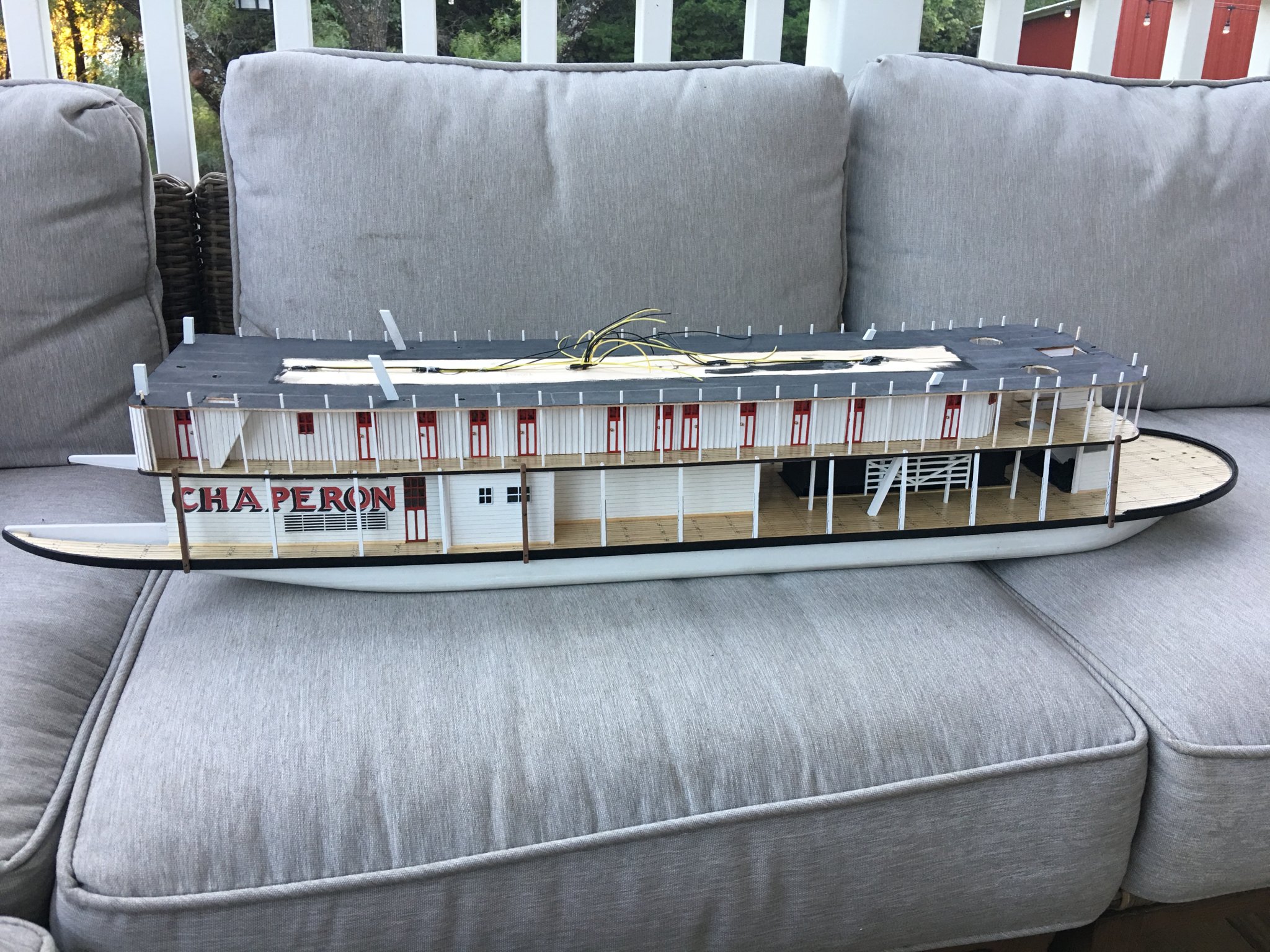
A little progress has been made on my Chaperon.
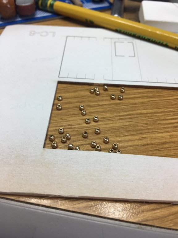
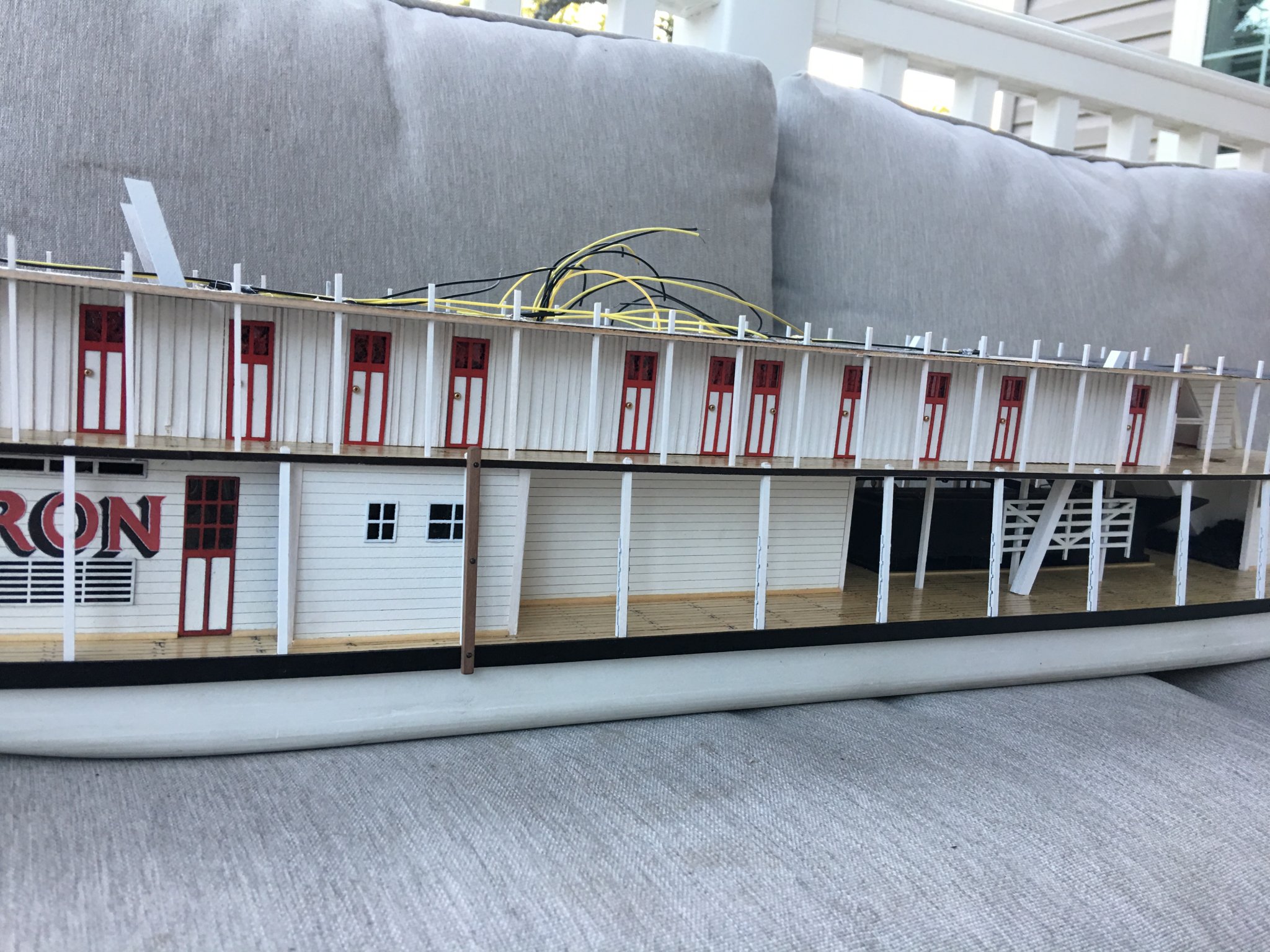
I was finally able to locate my door knob beads (of course it was in the last box I opened) and got them placed. Now all of the rooms and hallways on the Boiler Deck are accessible.
I also completed the bulkheads to help straighten the walls. Seems to have done the job. Not only will this align the walls but it will give me a better base for the Hurricane Deck.

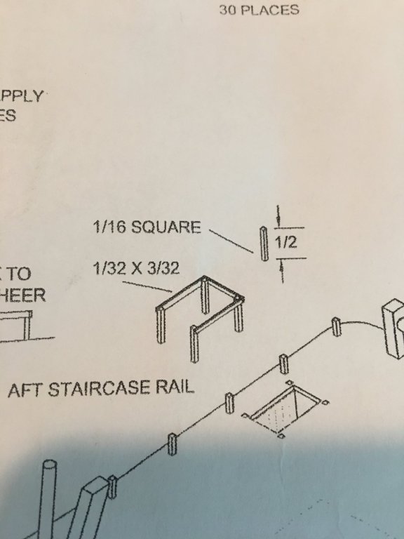
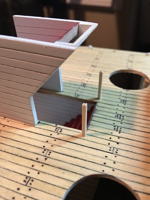
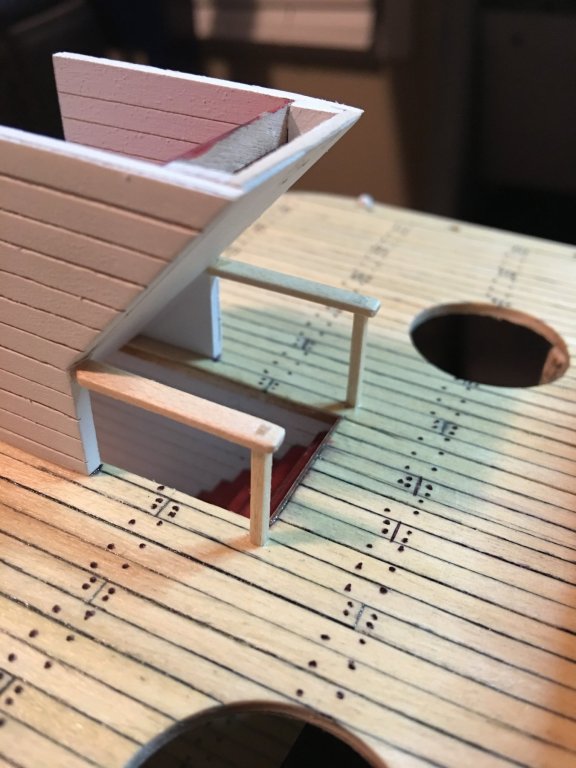
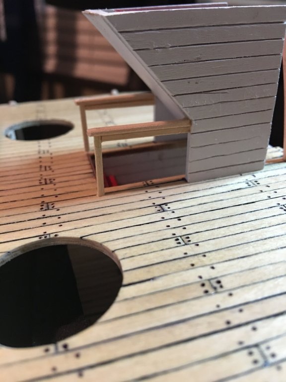
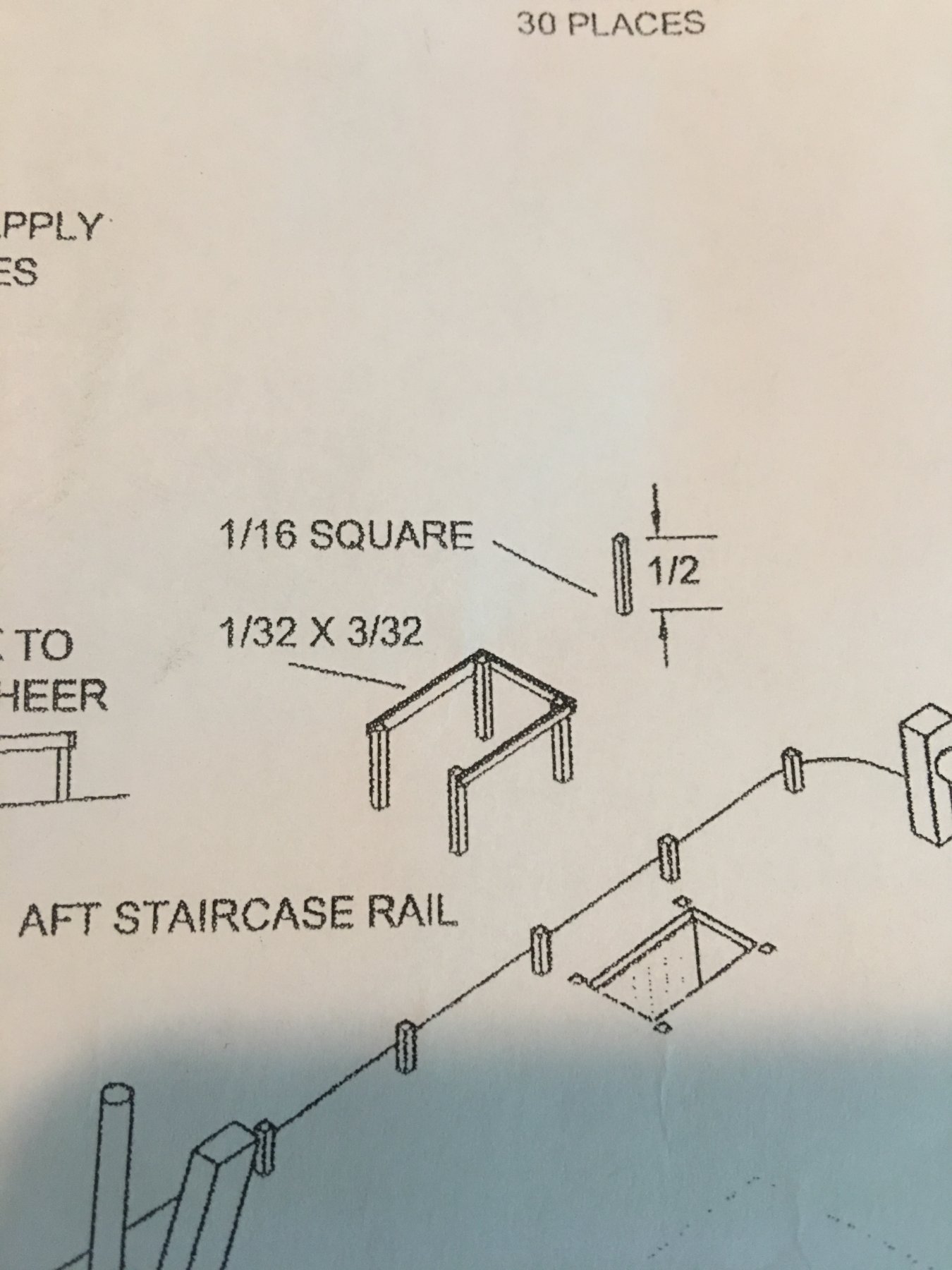
I also added railing for the forward staircase coming up from the Main Deck to the Boiler Deck. I modeled it after the plans for the ones on the Hurricane Deck. Nothing too fancy, just thought it needed something besides drop off to the stairs below.
I found a very interesting site for the University of Wisconsin. https://uwdc.library.wisc.edu/collections/LaCrosseSteamboat/ They have a complete library of Historic Steamboat Pictures. There are several of the Chaperon that give an excellent view of what she looked like in her hey-day.
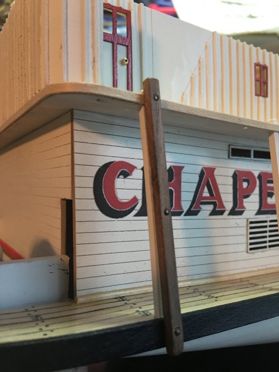
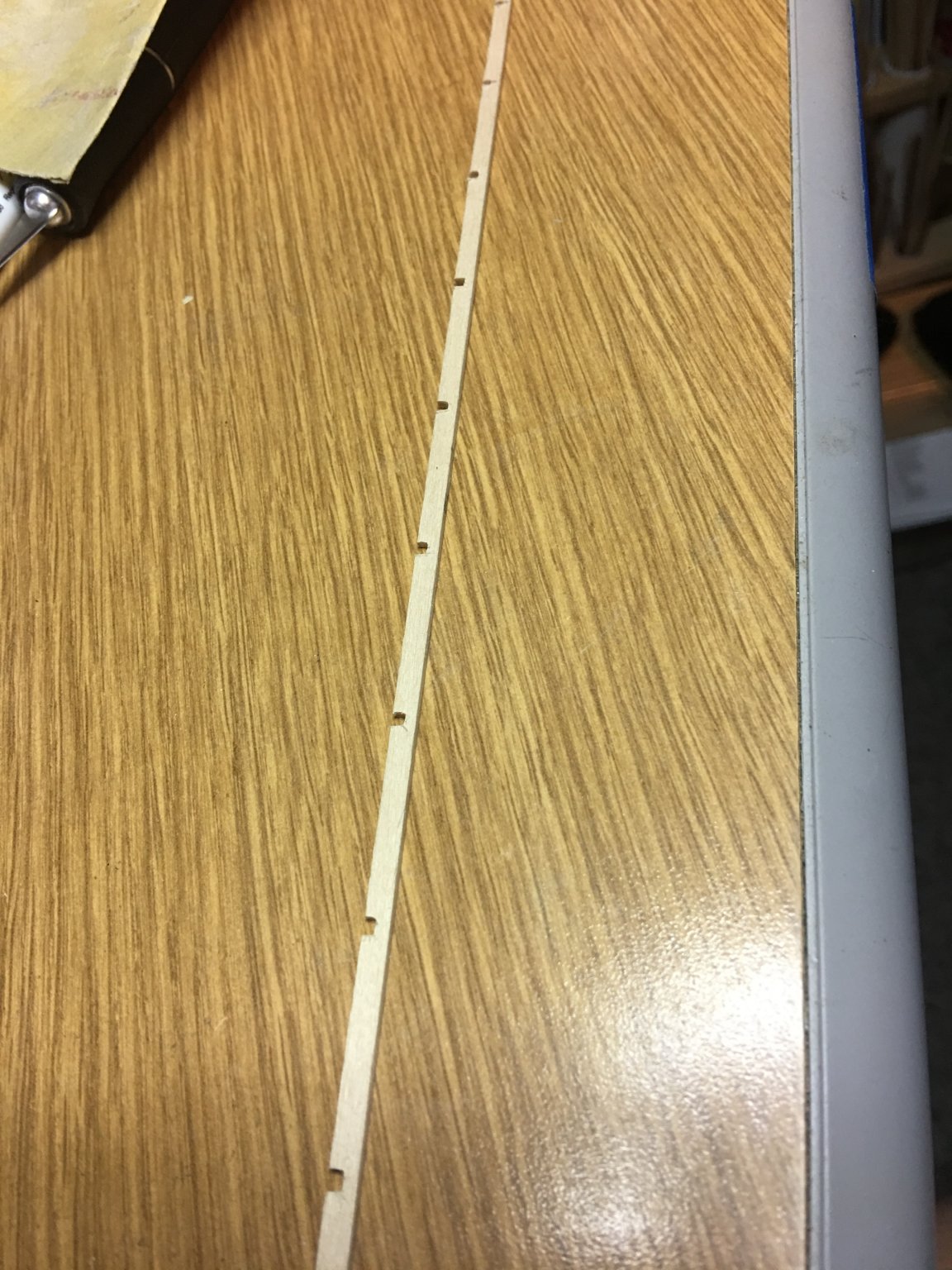
While looking at the photos of her, I noticed a little detail that I though would add a interesting touch of realism. In the photo below (and several others) I noticed that there are several vertical rub rails placed on the Main Deck stationaries. My assumption is that these were used when docking next to other steamboats to prevent damage to the sides. I fashioned these rub rails from some leftover walnut I had from a previous project and blacked a few brass nails to simulate the attachment bolts.

Finally, I completed the aft Boiler Deck staircase. From what I can tell at this point, there will need to be some adjustment made to the inboard wall. It seems to be a little thick. When I dry fit the Hurricane Deck I am not able to get the access hole to line up properly. It looks as though the inboard wall will need to be shave down a tad to get it to look right. I'll work on that.

Currently work has begun on the mast, but hasn't been completed. I'll post more pictures of it next time when I'm done with it.

On a side note, I have been seriously contemplating doing a scratch build and I have been weighing several options. Ironclad have always been a fascination of mine since I was a kid and visited Vicksburg National Park and saw the USS Cairo. I would love to do a build of the Cairo, but unfortunately there are no large scale wood kits of her only small scale resin models. I've found a few build logs on other sites of 48th scale scratch builds where they mention plans obtained from the National Military Park at Vicksburg but I haven't been able to find a purchasable copy of them.
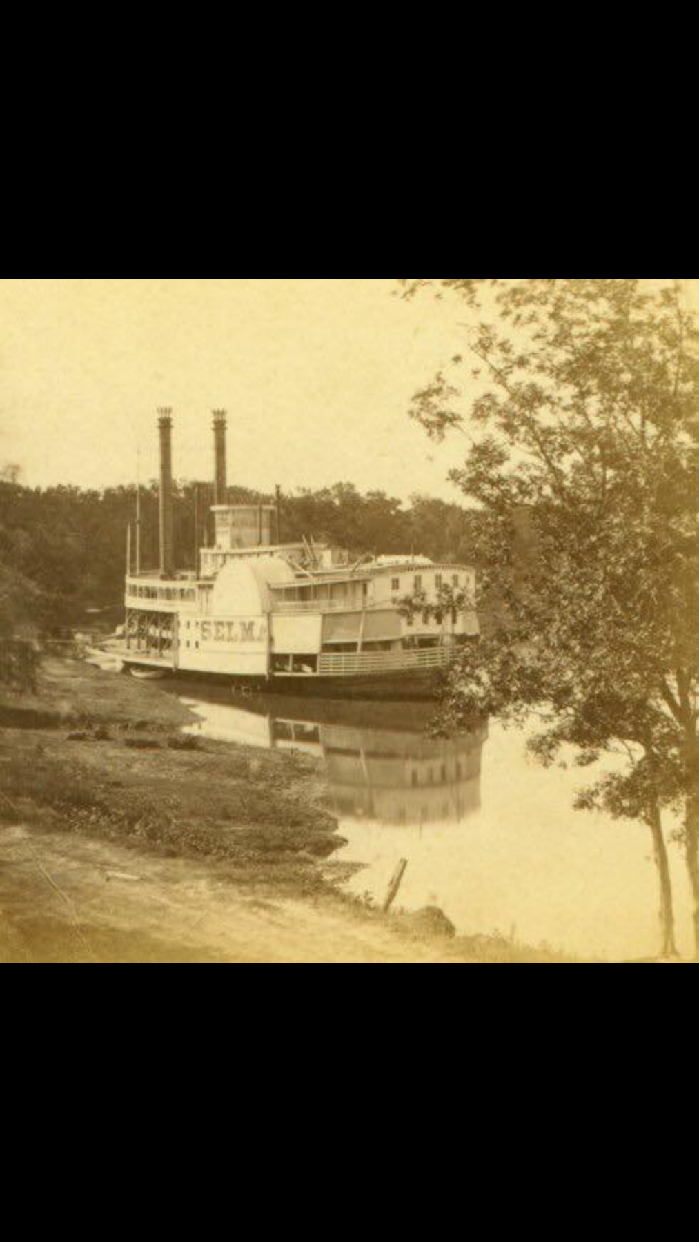
Another option is a side-wheel packet steamer. Every time I view Eric "Catheads" build log of the Arabia, it stirs my interest even more on building a side-wheeler. I was scrolling through Facebook the other day and I ran across an old picture of the side-wheeler Selma. She was primarily used in the Red river of Louisiana and other small tributaries of the Mississippi. With the exception of the picture below and a few other drawings, I have not been able to find a whole lot on her.
Either way, I still have plenty of time to decide while I complete my Chaperon.
As always, thank you for looking.
-Brian
-
Hello again Everyone,
It's nice to be back at it again, albeit at a slow pace, but at least I'm getting something accomplished.
The bull rail brackets have been installed on the stationing, I think I am going to leave the bull rails off until I'm just about done. There are still several things that I need to do before installing them and they'll just be in the way.
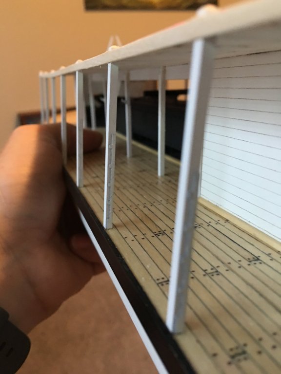
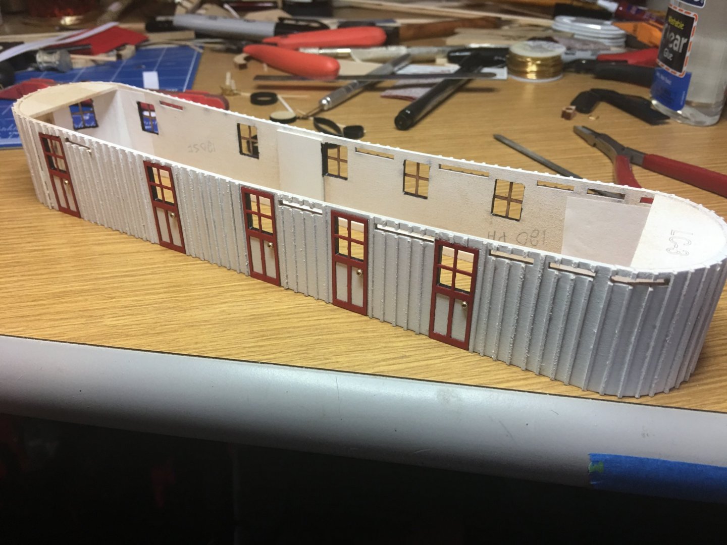
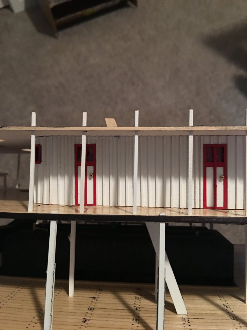
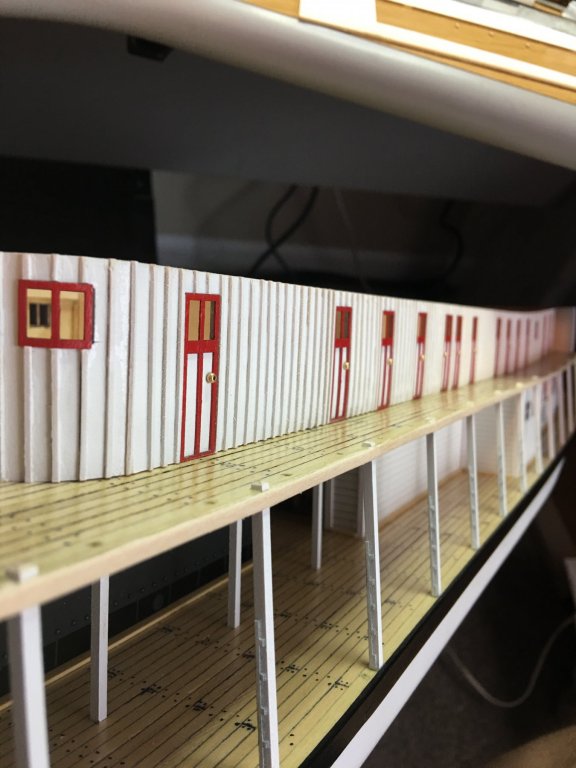
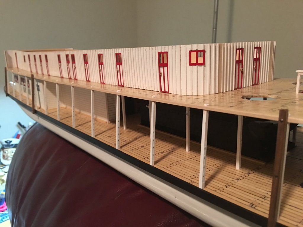
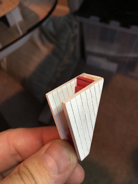
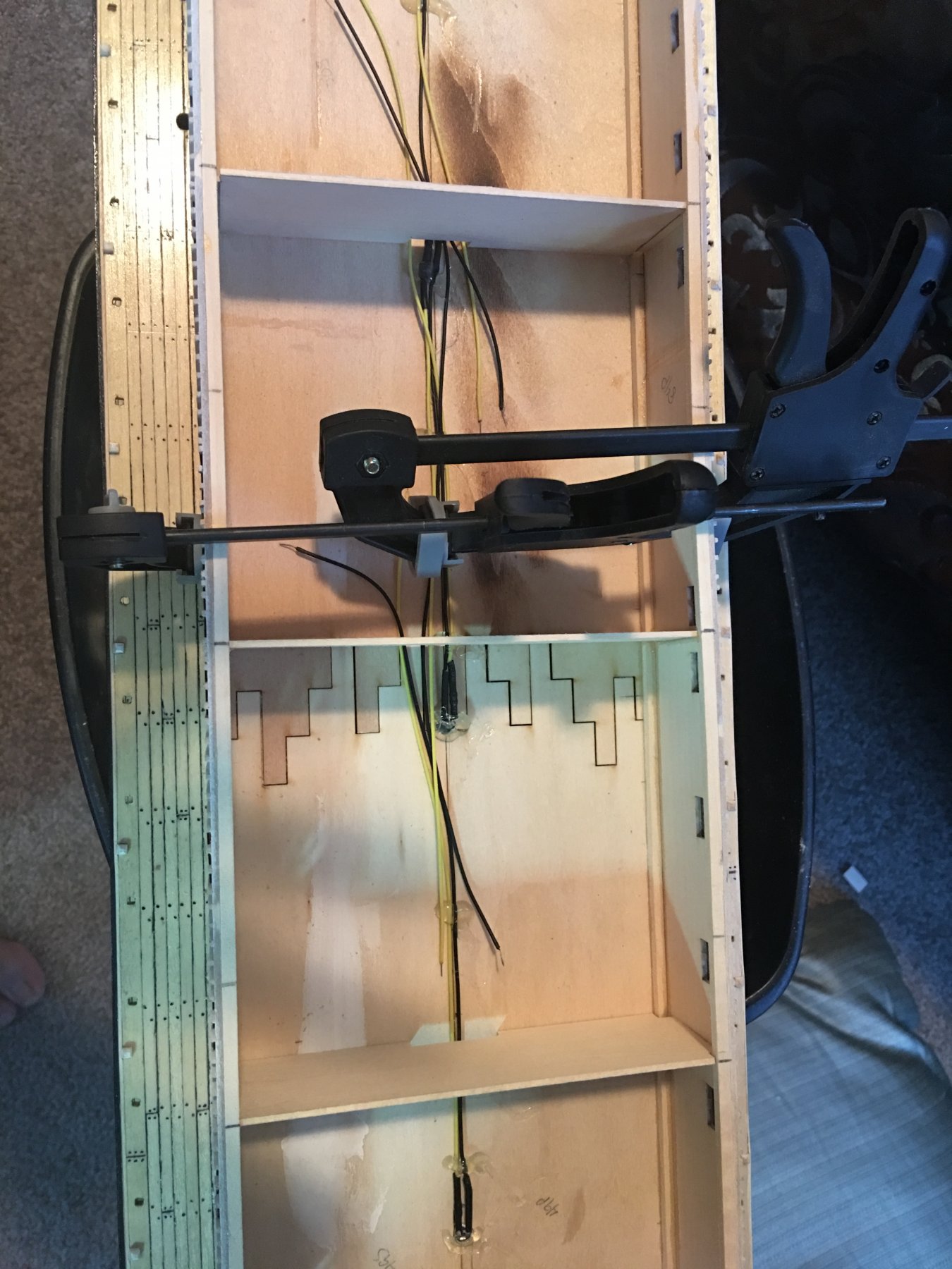
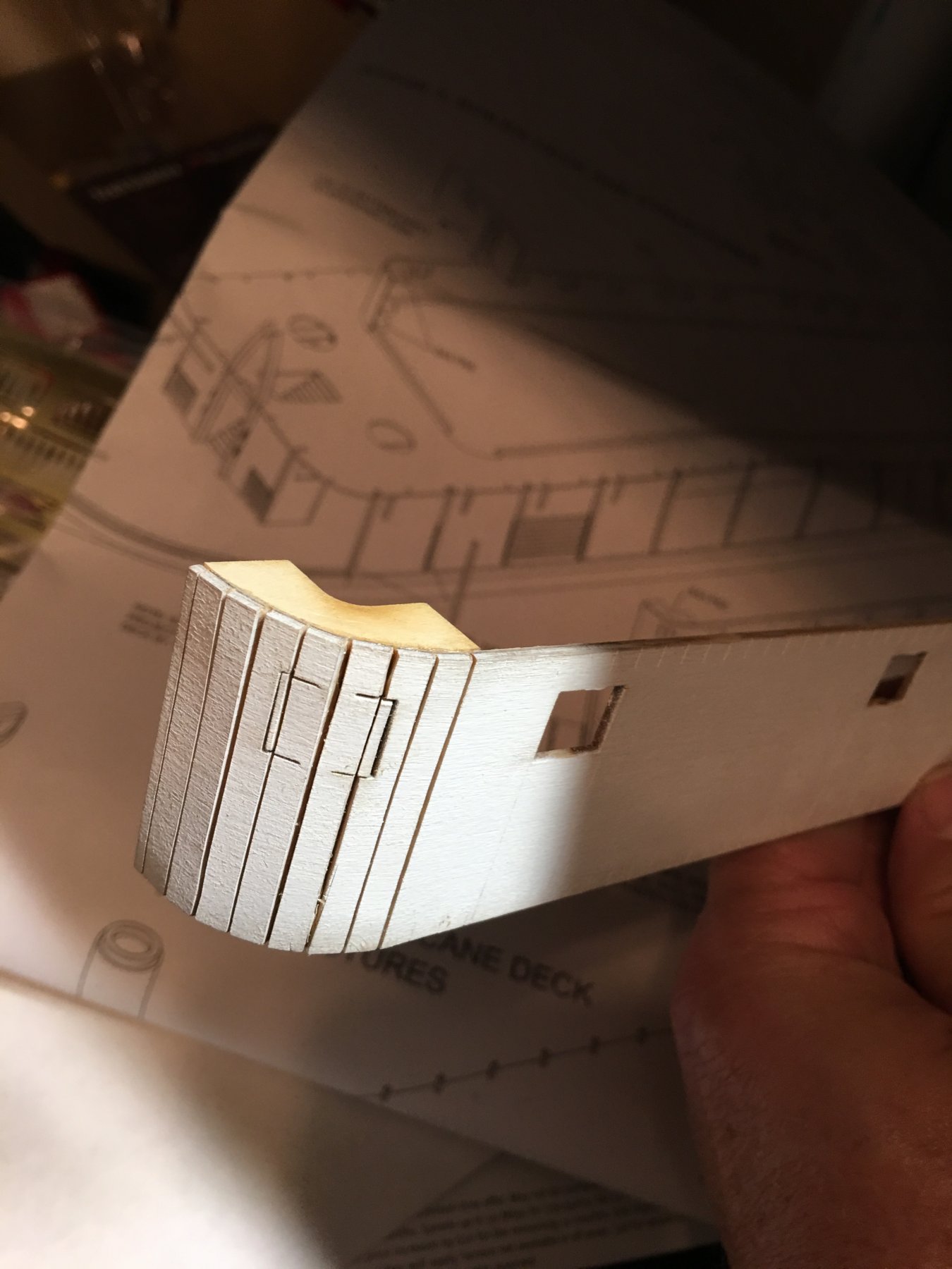
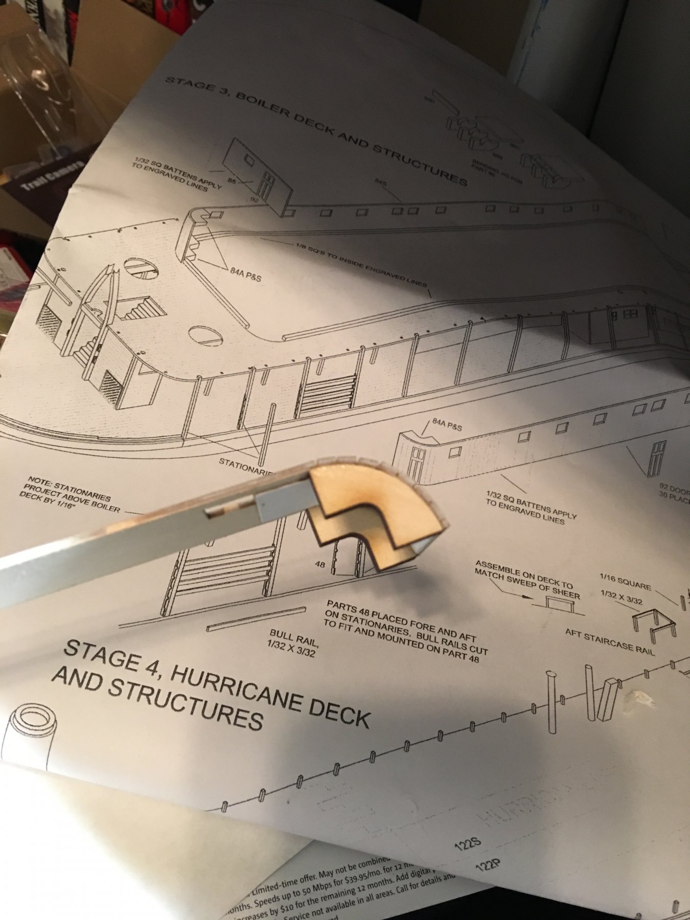
Work then began on the boiler deck walls. Getting the radius formed just right was pretty simple with the braces provided with the kit. Cutting the walls just right to where they would form around the braces without cutting all the way through was the biggest challenge.

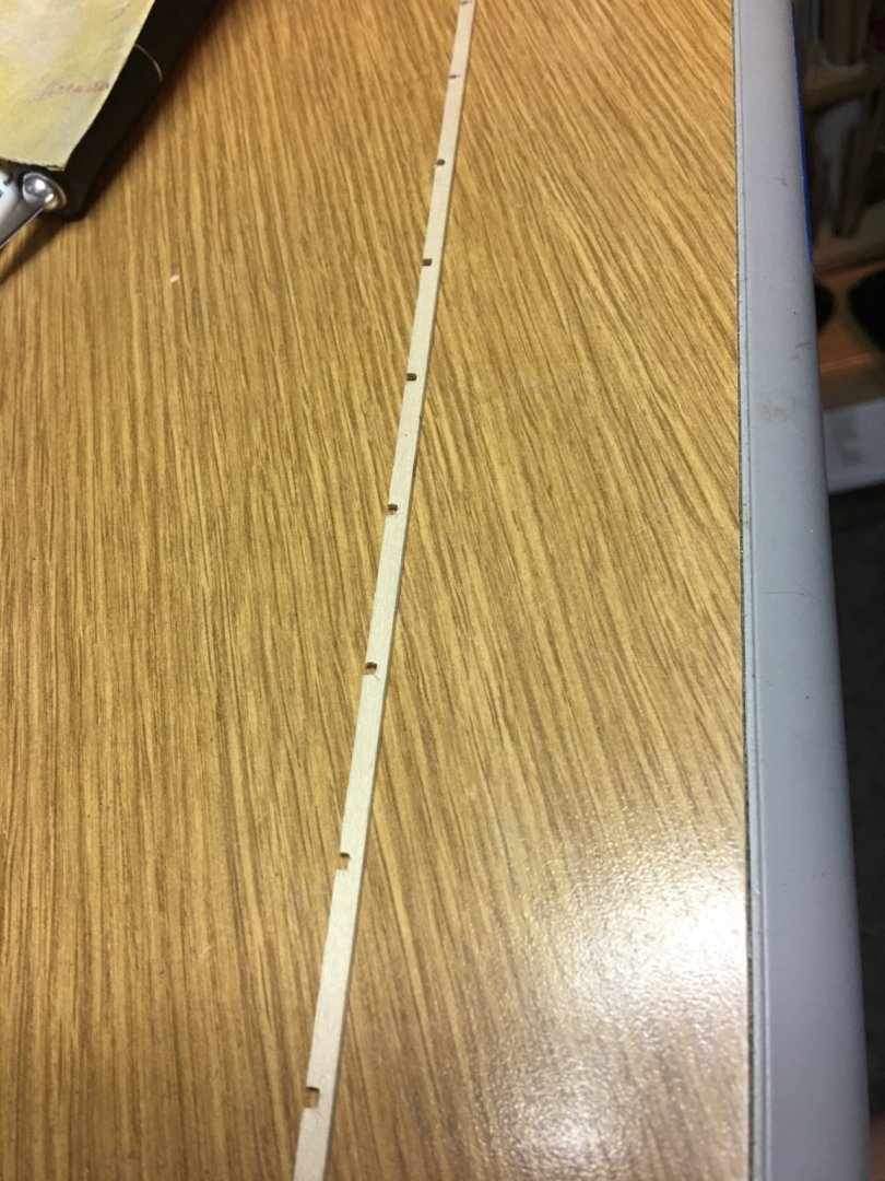
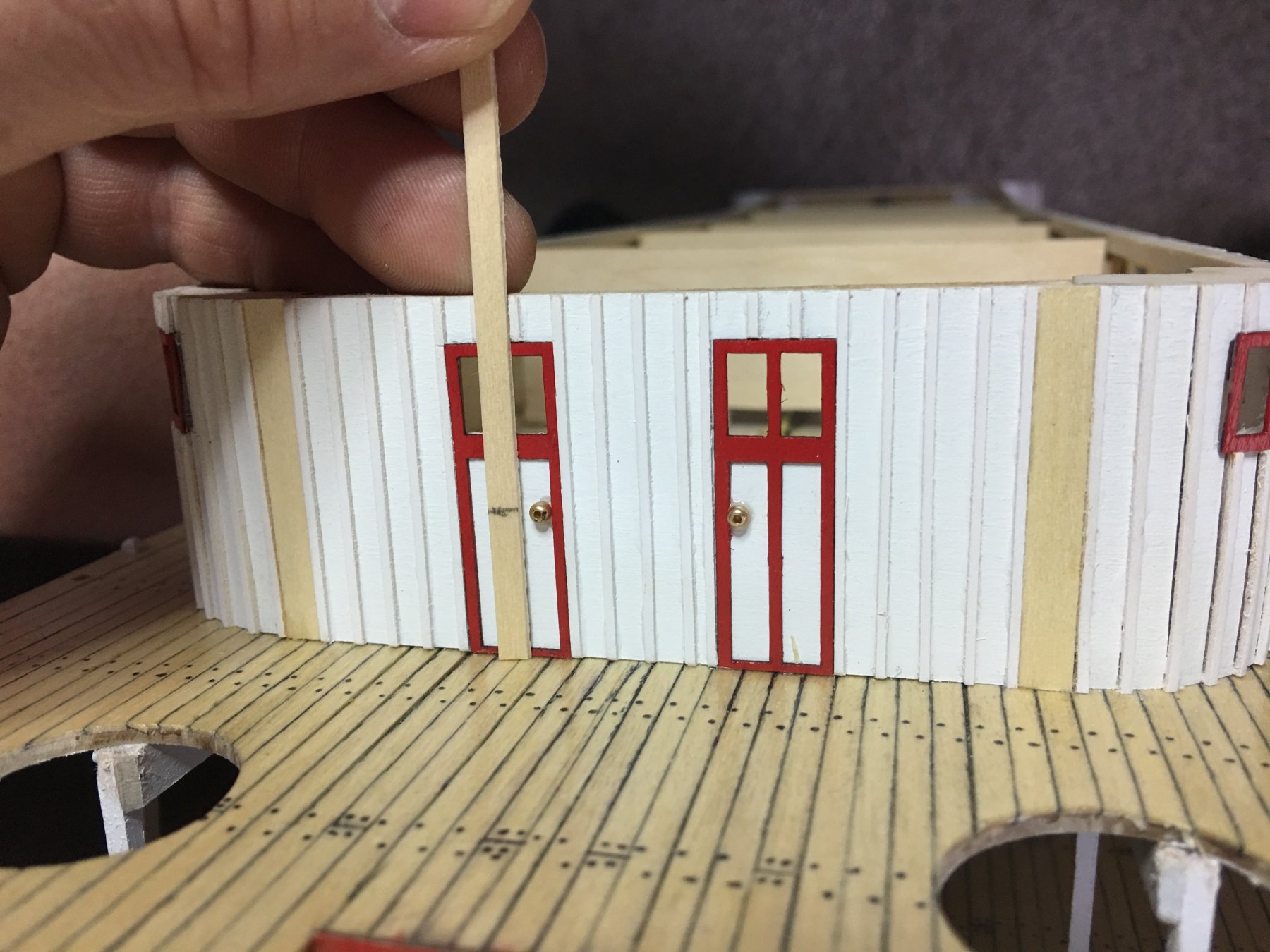
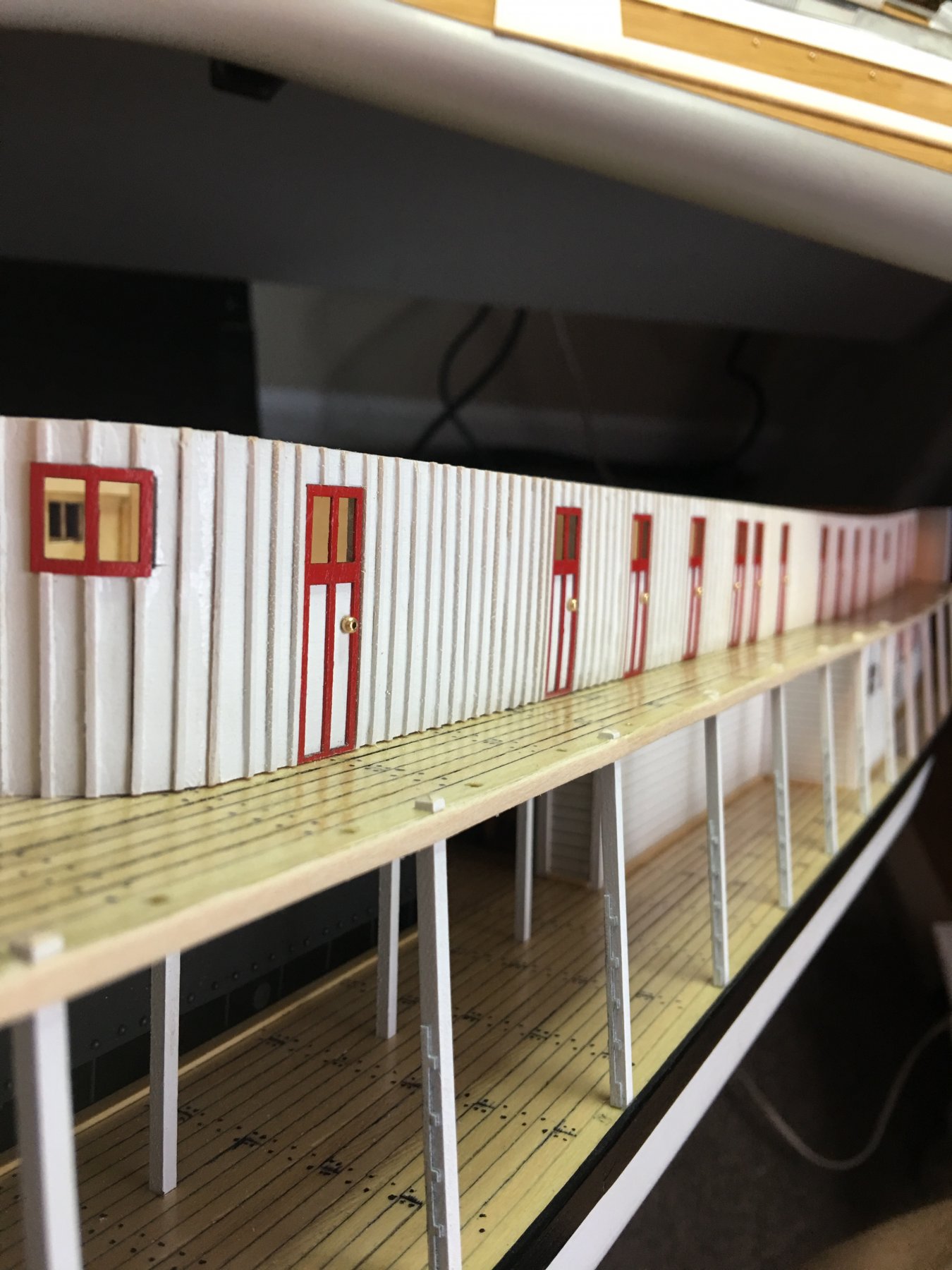
Then came the tedious part of the build, adding all of the battens. Monotony at its best. I may have dozed off a time or two because I found a few that were not quite on the prescribed lines. Nothing a little paint can't hide though.

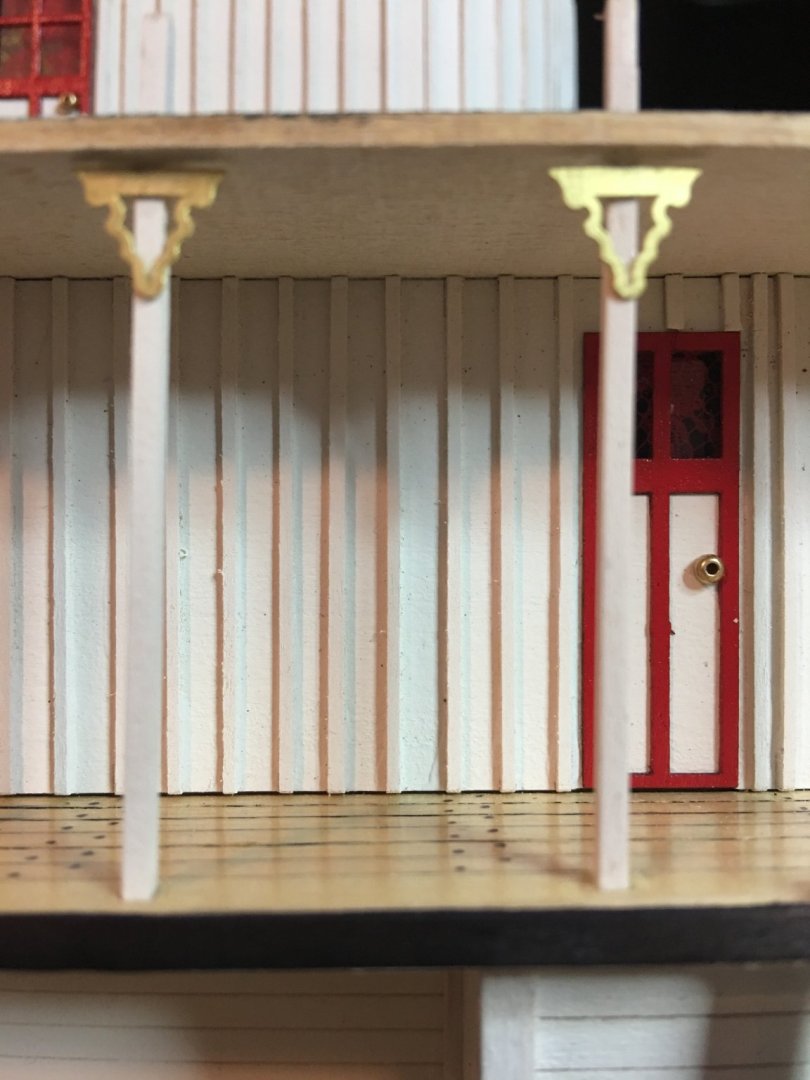
Besides adding all the battens, I think the toughest part of this build was getting the front wall lined up even and straight. The side walls had a slight bow to them which caused the curved part of the wall to want to lean out. Not a huge problem that a few clamps and rubber bands couldn't solve.
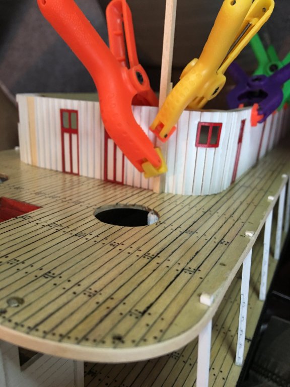
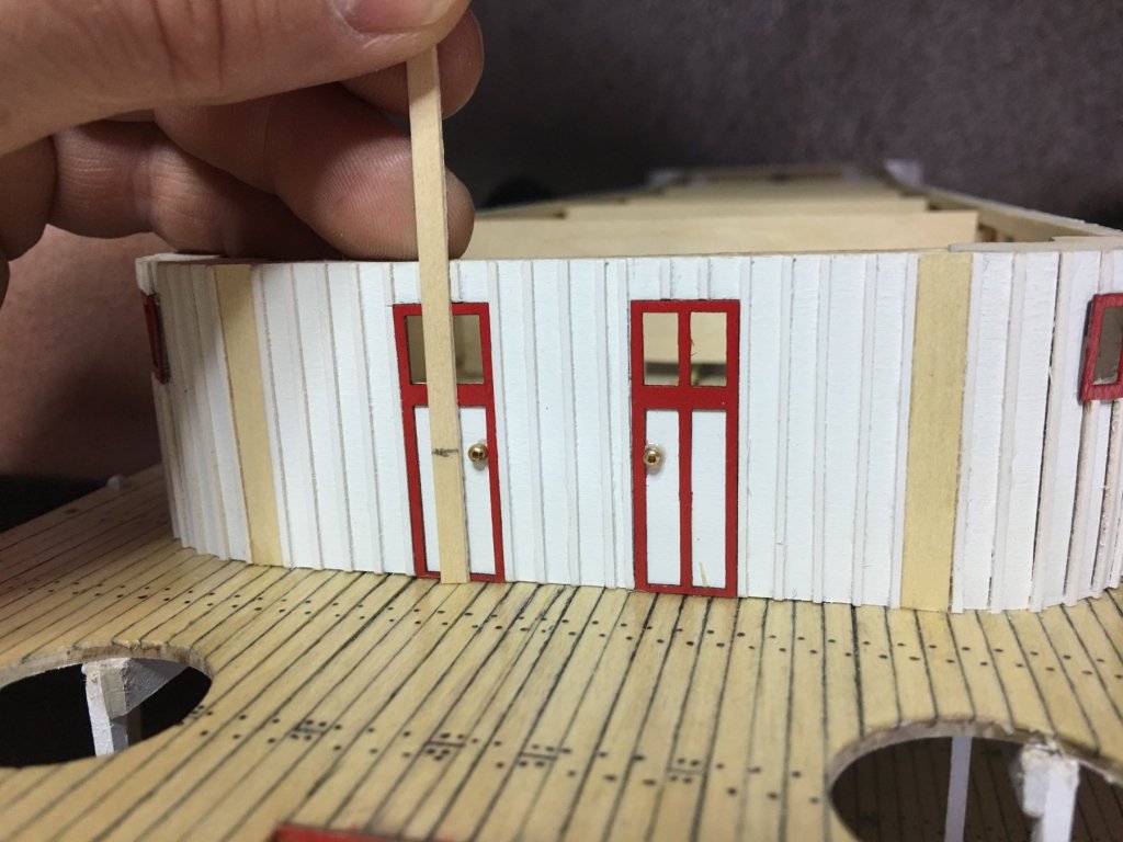
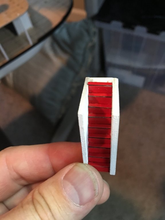
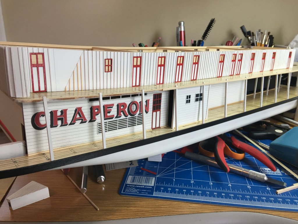
All the doors were added as well. I decided to go with red door frames. I was thinking that they just blended into the walls too much and pretty much disappeared with them painted white. I just need to go in and add the door knobs as soon as I can find my small beads that I use for knobs. I hate moving, I can never find anything when I need it.
I also started working on the forward stairs. I am contemplating adding hand rails to them as well as railings around the sides on the main deck stairs. Seems to me that it's sort of a hazard to leave them just open on the sides for some unsuspecting passenger (or crew) to inadvertently stumble over the side and down the steps. I know that OSHA wasn't around back then, but it seems that with a boat that carried passengers, some sort of safety features would be in place. Still not sure of how I am going to do them, I see a little more research in the making.
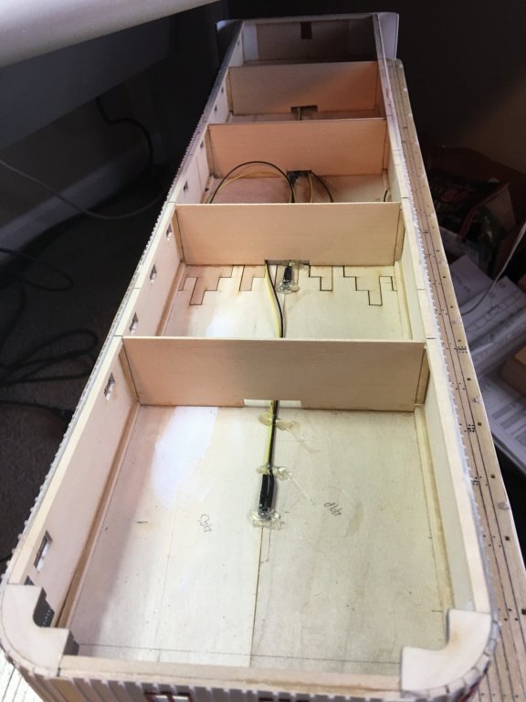
Finally, I decided that I was going to go with lighting things up. I did this on my King of the Mississippi build and liked the results, so I figured why not. I have some leftover LED's so I'm going to put them to good use. Only this time I am going to make it battery powered instead of AC. So I placed a few LED's along the main deck in places that would highlight some of the features on the deck.


I'm going to start working on the side staircase and making some bulkheads for the cabin walls. The supports that I have on there right now are not taking all of the bow out of the walls like I want them to. I figure about four should get them straight enough. We'll see. Now to go hunting for my door knob beads. Only four boxes to go through.
As always, thanks for looking.
-Brian

- Jack12477, GrandpaPhil, Canute and 3 others
-
6


Arabia 1856 by Cathead - FINISHED - Scale 1:64 - sidewheel riverboat from the Missouri River, USA
in - Build logs for subjects built 1851 - 1900
Posted
Eric,
Beautiful work on the Arabia, those compound curves on the aft decking look like they were a bit tricky to lay down the wood sheeting. Especially with the delicate structure beneath. She’s really looking good.
I love the the idea of milling your own wood, I have 15 acres of cedar trees myself, along with some other hardwoods (pecan, oak, bois d’arc, mesquite, etc.) spattered about, that I would love to use for future builds. What is your process to cut the wood down to these strips? Just curious, I’d like to do the same instead of just burning what I clear out.
-Brian