


mbp521
-
Posts
1,003 -
Joined
-
Last visited
Content Type
Profiles
Forums
Gallery
Events
Posts posted by mbp521
-
-
Roger, Wefalck,
Thank you both for the information. It’s very much appreciated. I had no idea that farmers used the same red on their barns. That would explain why you can still see remnants of red paint on some of the old dilapidated barns, as well as some still standing. The paints actually last longer than the wood.
I am seriously considering going with a reddish-brown hull, it seems the general consensus points that direction anyway. I have a few inquiries out to others, a couple of which are outside of this forum, with the same question, and so far the answer has been the same, “not a lot of info on it” and “go with your preference”. I think I’ll play around with some colors and see what comes out. I still have some time.
-Brian
-
John,
I very much appreciate the info on the officers cabins. It will come in handy when I reach that point of my build.
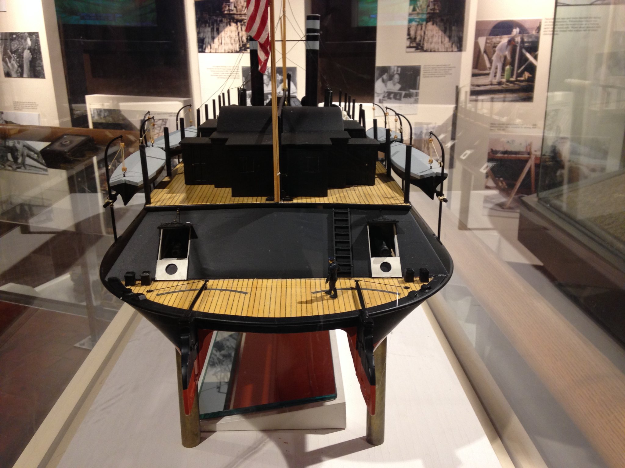
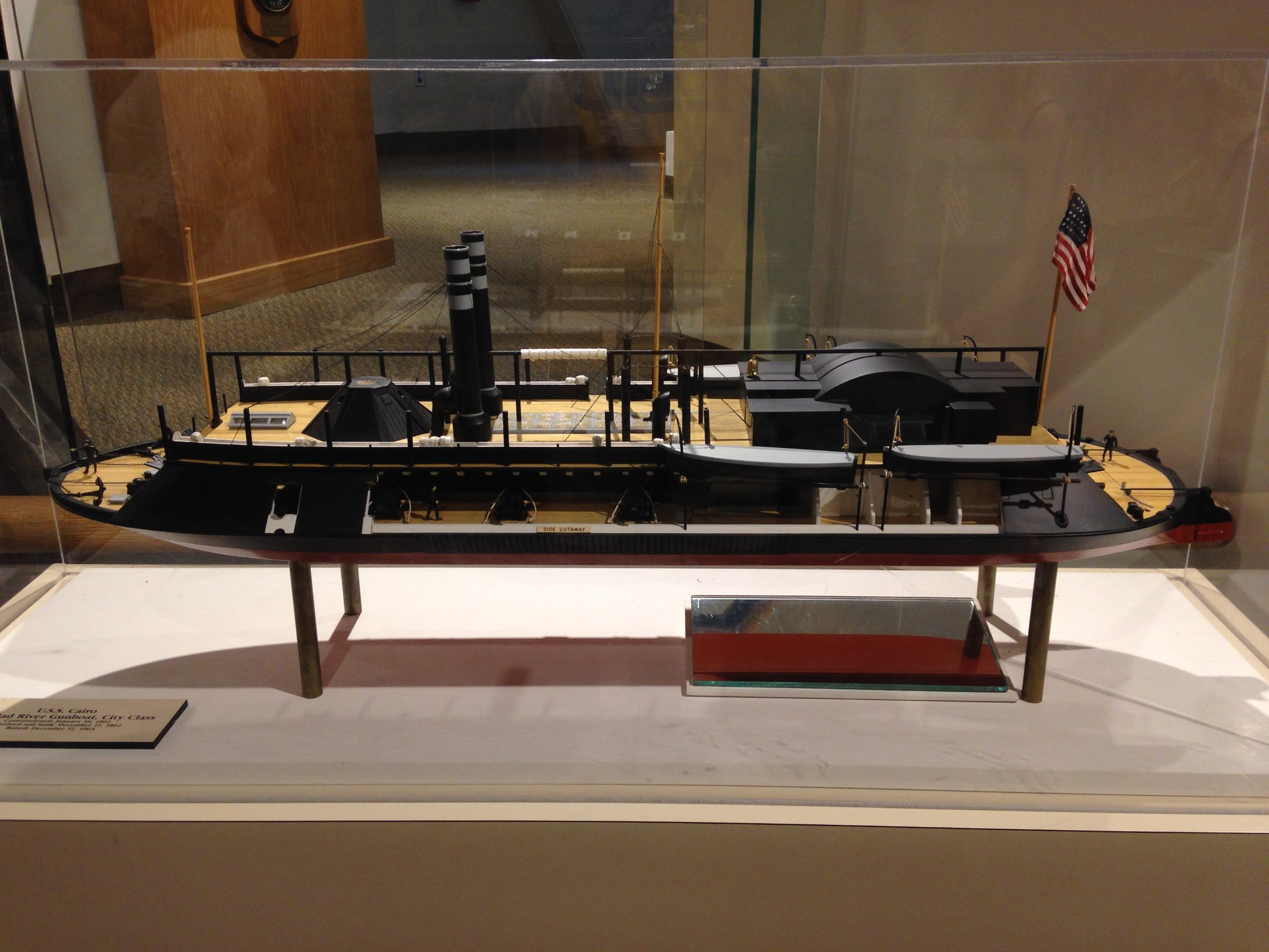
If I may, I’d like to pose another question. I am at the point in my build where I am ready to paint my hull. I’ve done some research on this but keep coming up empty. The Cairo museum has a model on display that has the more modern looking red hull below the waterline and black on the rest of the vertical surfaces. I am wonder as to how accurate this paint scheme is. I like the look of the red hull, but I’d also like to keep my build as historically accurate as possible. Have you guy run across any information that would justify the use of red on the hull or is this one of those mysteries that may never be solved?
Any advice or direction would be greatly appreciated.
-Brian
-
Eric, great idea! Hadn’t thought about that. I’d have to email them though, unfortunately the museum has been closed since summer due to the ‘Rona’.
I guess I could also pose the question on the log for the St. Louis. I know those guys have done extensive research on that build.
-Brian
- FriedClams, Canute, mtaylor and 1 other
-
 4
4
-
Keith, thank you for the kind words. I have a feeling you are correct, given the stringent time frame these boats were built on. I would probably say that they just slathered them down top to bottom with a coat of black paint and sent them on their way. Cairo’s service life was so short she probably never made it to a dry dock to have my hull work done, so it most likely remained its original color.
Unfortunately there are no records to prove or disprove this. It may all boil down to a coin toss, which will be heads on both sides, meaning red it is. That is, unless I happen across some hidden document that calls out her original paint scheme, or someone out there has done extensive research on how the hulls were treated.
Pat, what I wouldn’t give for a “way back” machine, not just to get a picture of what she looked like, but to also see these beautiful machines in action (from a distance of course).
On a different note, I have done some studying up on the model in the museum and there are several discrepancies with it, in comparison with the HSR. And not to discredit the builder(s), they did a beautiful job on it, and for the most part it’s fairly accurate. But I do think they took a few “builders liberties” with it as well. I’ll be more than happy if mine comes out looking as good as this one.
-Brian
- Canute, mtaylor, FriedClams and 2 others
-
5
-
Hello again Everyone,
It's time again for another episode of "Ask the Audience".
I have been working on getting my hull faired and completed so that I can get it painted to where I don't have to flip the model over anymore. I getting to the point where the deck structures will prevent the boat from being turned over without the risk of breaking something off. So in the process of researching the hull painting, I ran into another quandary that I cannot seem to find any information on.
I know that the regular packet steamer hulls were generally painted, along with everything else above the waterline. And I know from research that the Iron Clads were also painted above the waterline as well, given the numerous pictures available on the internet and in books. This stands to reason that their hulls would have been painted too, to give the hull some form of protection from water absorption, even if their expected life span wasn't that long. The problem that I am having is what color was the hull painted? I have found several instances where the model builder painted everything below the waterline something of a Red Oxide color, similar to that of more modern steel warships (and other ships). In my limited knowledge of modern ships, I have come to understand that the Red Oxide hulls were a rust preventative and to help with keeping marine parasites like barnacles from fouling the hulls. This is all fine and dandy, but the USS Cairo was a wooden hull boat that travelled in fresh water. So what would be the reason for the red hull? Since the Cairo spent over a 100 years at the bottom of the Yazoo river, none of the paint survived, which makes it really hard to determine what colors were used.
My ultimate goal is to get my build as close to accurate as possible. I like the red hull color scheme, but was it authentic? This may be one of those time where "Builder Liberties" come into play, but if anyone out there has any input that would help it would be greatly appreciated.
These were some pictures of the model in the USS Cairo Museum that I took on my last trip there. It shows the red painted hull. There are a several other pictures that I found of models on the internet that have red hulls as well as black ones. I didn't post them here because I wasn't sure of their copyrights.


Thanks for looking.
-Brian
-
Beautiful job Kevin. Excellent build.
-Brian
- Kevin and mort stoll
-
2
-
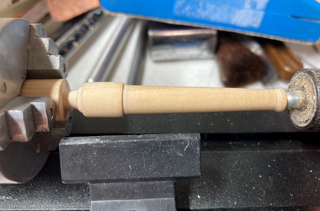
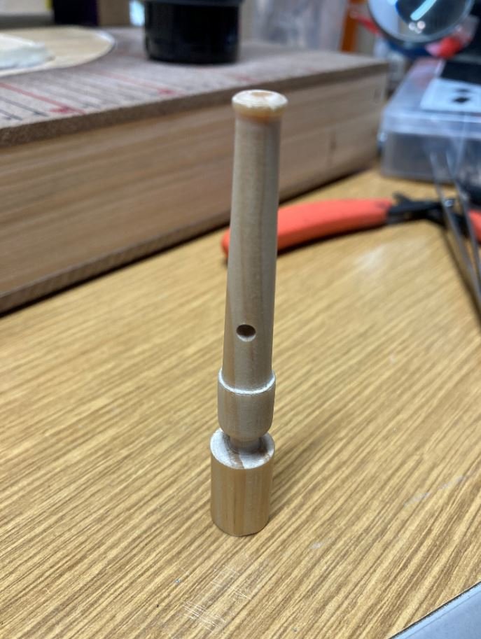
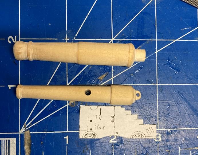
So after a little more research, I determined that you were right Keith, The muzzle swell on the 30lb parrot rifle was a little bit much.
I found some pictures I had taken a few years ago when I visited Vicksburg NMP. Now given the assumption that these are the original guns that were brought up with the rest of the USS Cairo then the 30 pounder has a slight swell at the muzzle, a little less than what is shown on the HSR.
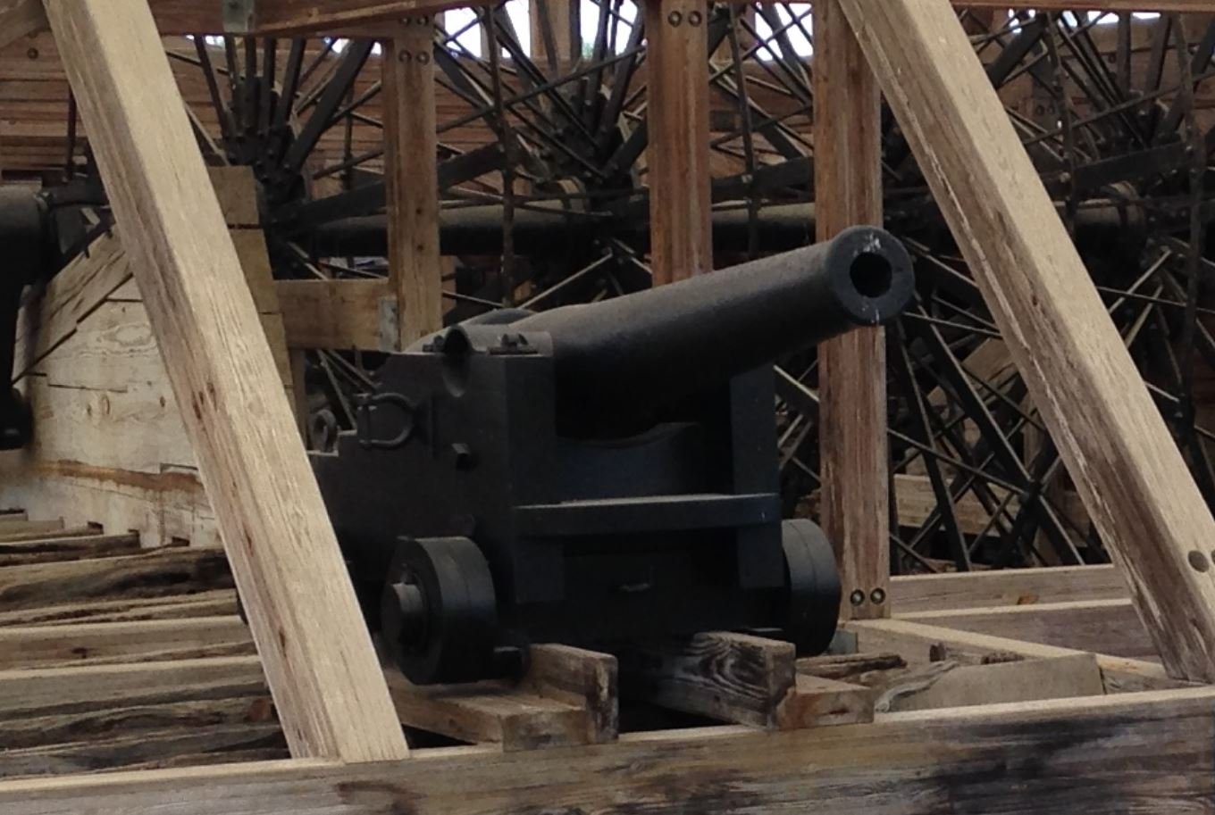
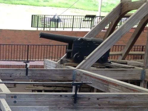
Compared to the HSR drawings, the real guns have less muzzle swell.
So with that all being said I decided to turn it down a bit. It might not be perfect, but I do think it looks closer to the actual gun than the drawing.
Thankfully there was only one 30 pounder on board. Now to build the carriages and figure out how to duplicate the other guns.
-Brian
- J11, Keith Black, leclaire and 7 others
-
10
-
Eric,
So sorry for your loss. What a beautiful dedication to him. It sounds as though he was a great man who lived a wonderful life and will be dearly missed.
Your build is progressing very nicely, glad to see that you have been able to overcome all of the obstacles the build and life have thrown your way.
Very nice job on the decking, much better results than the kit provided “scribed” planks. Definitely adds a touch of realism to it.
Do you plan on repainting the hull, or are you going to leave it as it is currently. Personally I think the way it looks right now gives it a very nice “weathered” look as though it has seen many beaching and days along the docks.
-Brian
- BobG, FriedClams, Cathead and 1 other
-
4
-
YIKES! That is a serious parrot problem.
-Brian
- mtaylor, Keith Black, Canute and 1 other
-
4
-
Keith,
Thanks for the additional pictures. What a plethora of puzzling Parrot problems.
-Brian
- J11, Keith Black, mtaylor and 2 others
-
5
-
4 hours ago, Keith Black said:
Brian, beautiful work. I am enjoying your build and look forward to each new installment.
One thing if I may, while your turning of the 30 lb Parrott rifle is beautiful, it looks like there is too much muzzle swell. I've seen photos of 30 lb Parrott rifles that have no swell as per the attached photo but then other 30 lb photos show a very slight swell. I once had tons of Parrott rifle photos when doing research for the Parrots on the Tennessee but have since deleted them when I finished the guns.
Please don't take this as criticism, merely a small point that you may want to look at more closely......Keith
Keith,
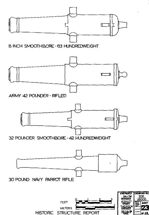
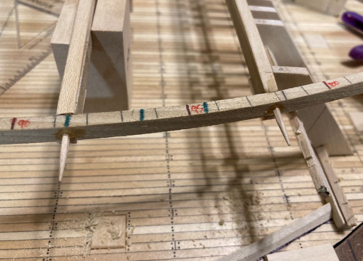
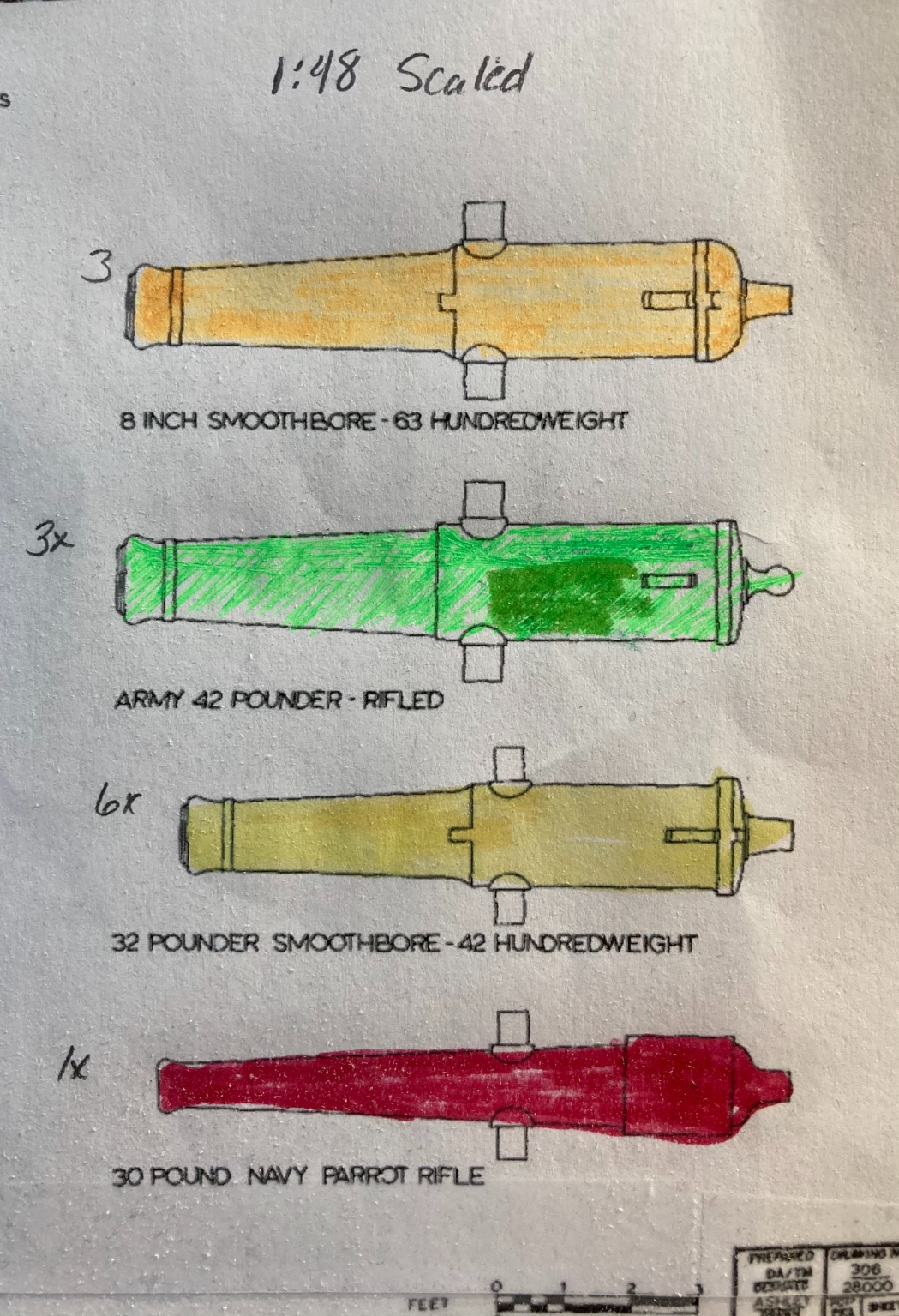
No worries about the criticism, I openly welcome it. Any tips, guidance or pointers I’ll gladly accept. To be honest, I really didn’t do a whole lot of research on the guns for Cairo, I just took it for granted that the HSR document was correct on her armament. I based the guns off of the below sheet that was part of the HSR. This drawing has a significant muzzle swell on it. However, now you’ve got my curiosity up again on how they really looked. Time to do a little investigation. If you do happen to run across any other pictures of the Parrots that you may have, please feel free to share.
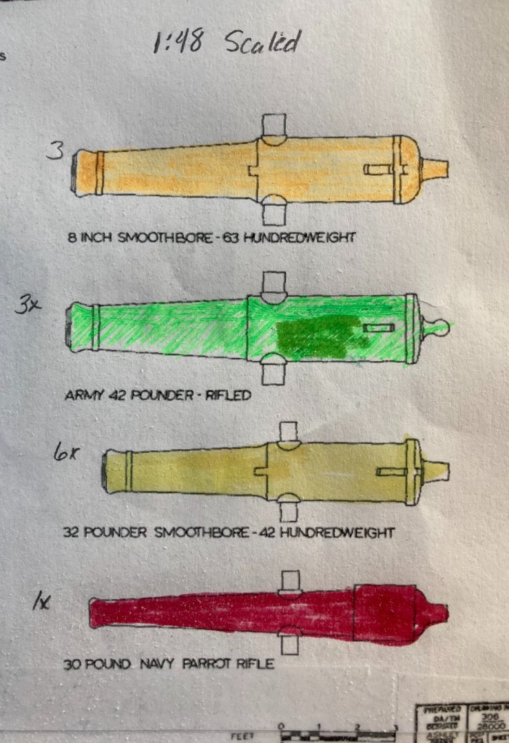
Please pardon my coloring. I color coded them for positioning on the deck.
-Brian
- Canute, KeithAug, Keith Black and 1 other
-
4
-
5 hours ago, Cathead said:
Looks wonderful, so crisp and even on the framing. Nice fix using the toothpicks to strengthen those joins. The guns look nice to me, though I'm hardly an expert.
Thank you Eric. That toothpick method has come in handy more than once on this build.
-Brian
-
Hello Again Everyone,
I have finally hit the six month mark on my build and figured it was time for another update. It has been slow going and I realized that it has been several weeks since my last posts, so I guess it is about time to get something out there. I am still chickening out on building the engines. For some reason, I just cannot get my head into them (not sure if it is mental or what). So instead I worked on the casemate framing for the gun deck.
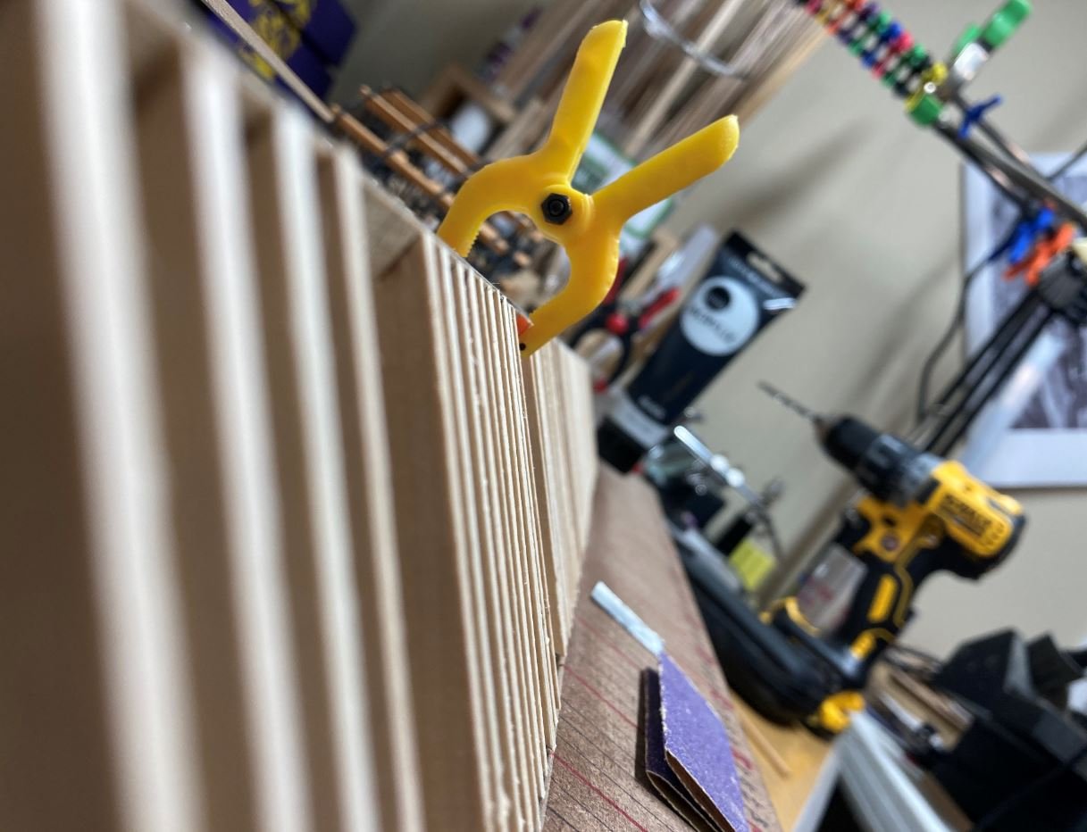
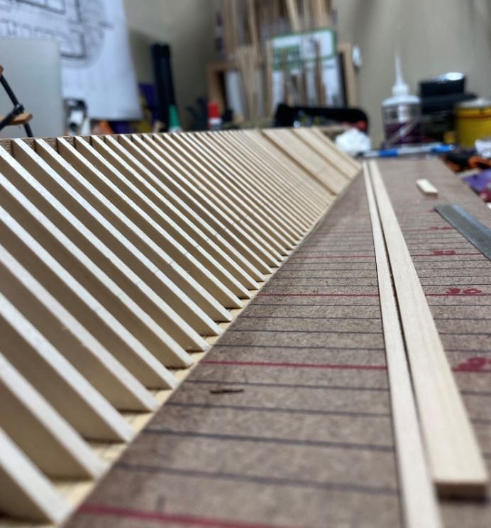
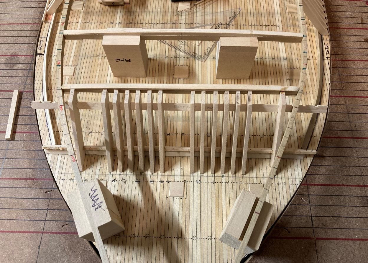
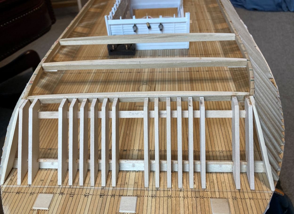
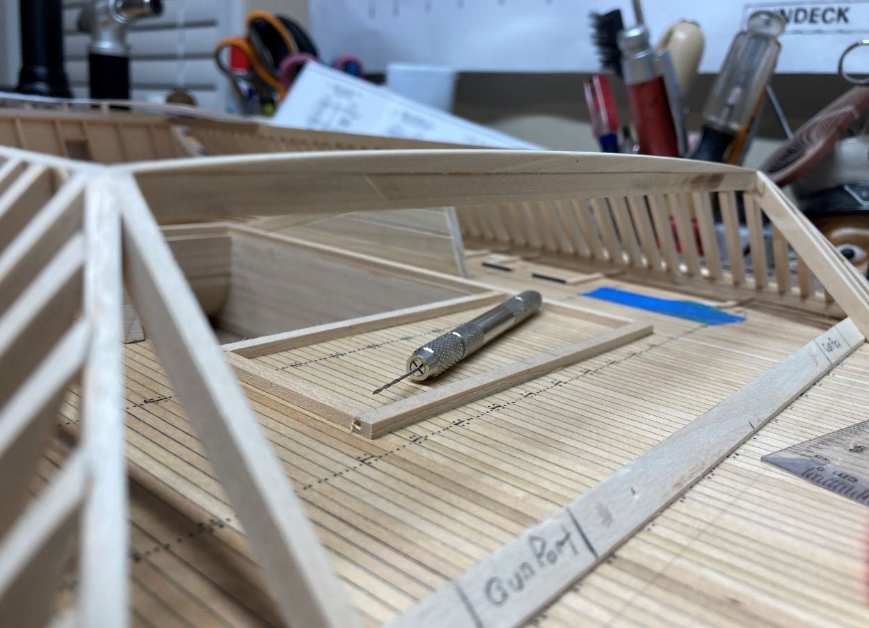
To start the framing, I set me up a jig that would allow me to keep the frames in a straight line and equal height. I use a couple of scrap blocks glued to both ends of by build frame and some 3/4" aluminum angle for this. For the top beam, I marked out the framing positions to also line up with the build frame and set that into place on top of the blocks. Then the beam and aluminum angle were lined up and clamped into place. The two middle blocks were left loose so that I could slide them next to the frames as they were going in to maintain a consistent height. Even though I use a solid piece of angle there was still some flex in the four foot span and I didn't want to risk my frames drooping in the middle.
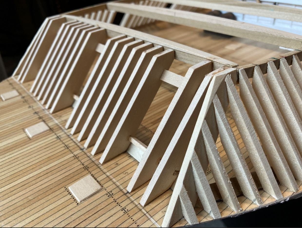
First few frames going in on the port side.

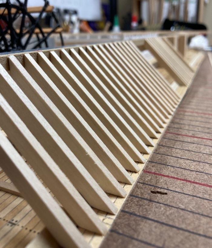
More frames going in.
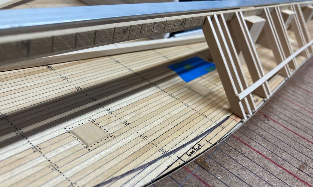
Looking pretty straight.
Starboard and port frames in place.
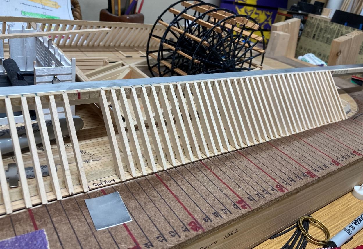
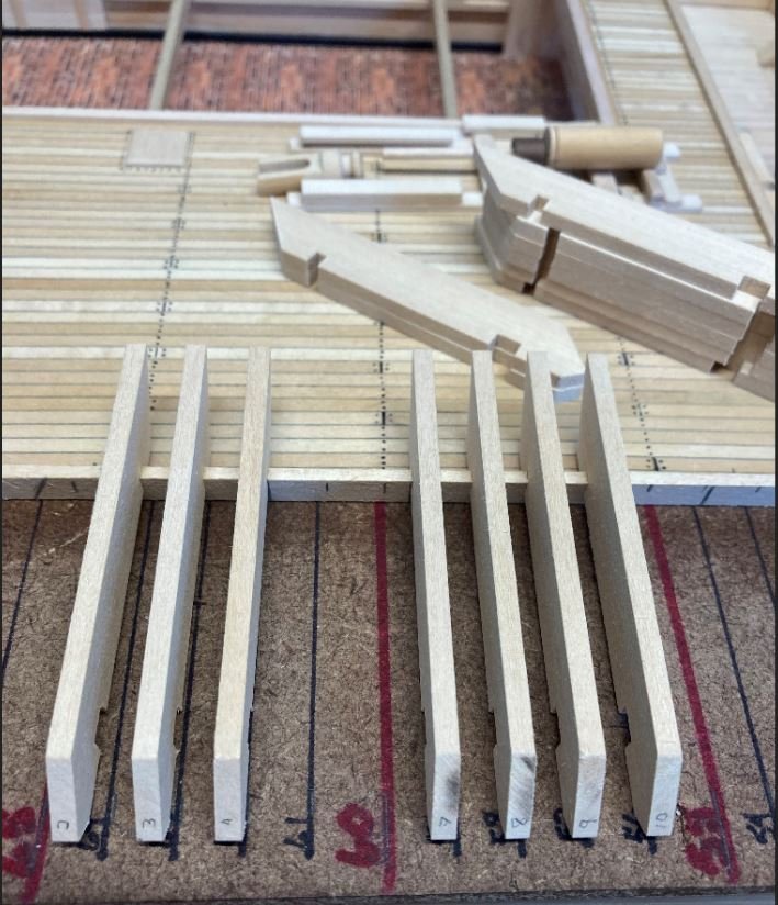
After the side frames were installed, I started work on the forward casemate frames. These were twice the thickness of the side frames for added protection on a frontal assault. On the real Cairo, the side frames were about 12" thick, the forward frames were 25" thick. This was not counting the armor plating that added an additional 2 1/2" of thickness.
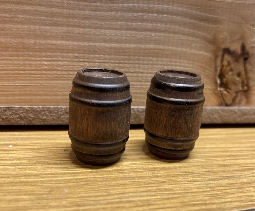
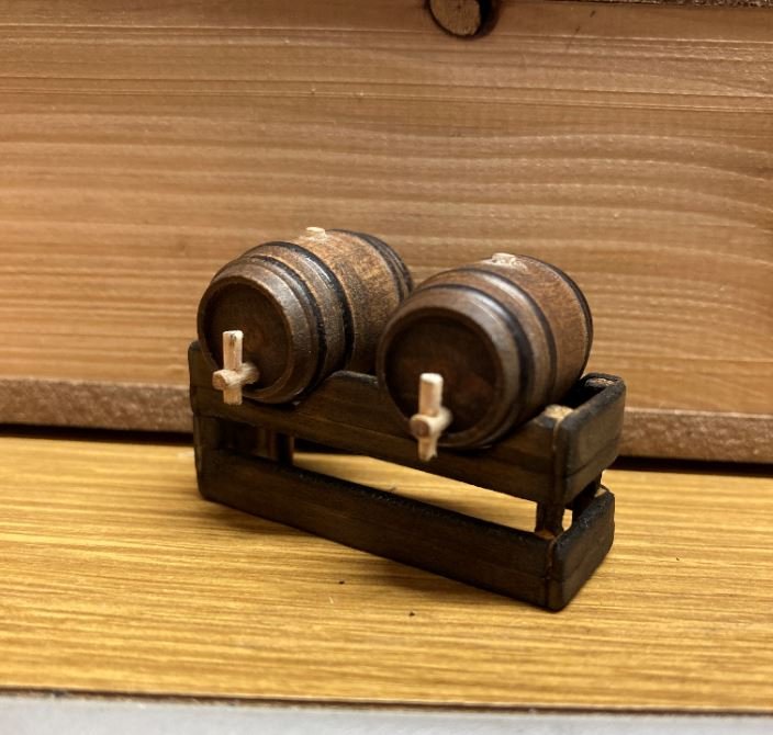
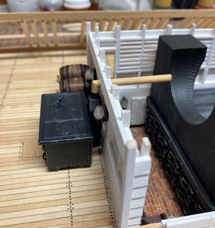
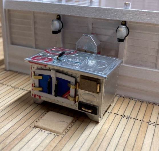
While I contemplated how I was going to form the curve of the top beam at the forward end. I started work on one of the deck features. I built up a couple of water/beer/wine casks (not sure what the preferred drink of the day was) and got them into place next to the stove.
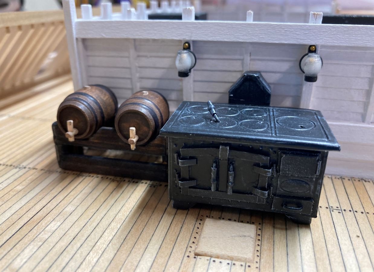
I went ahead and temp installed the stovepipe since I wasn't sure that I would be able to get my drill down in the deck once the forward frames and ceiling beams were in place.
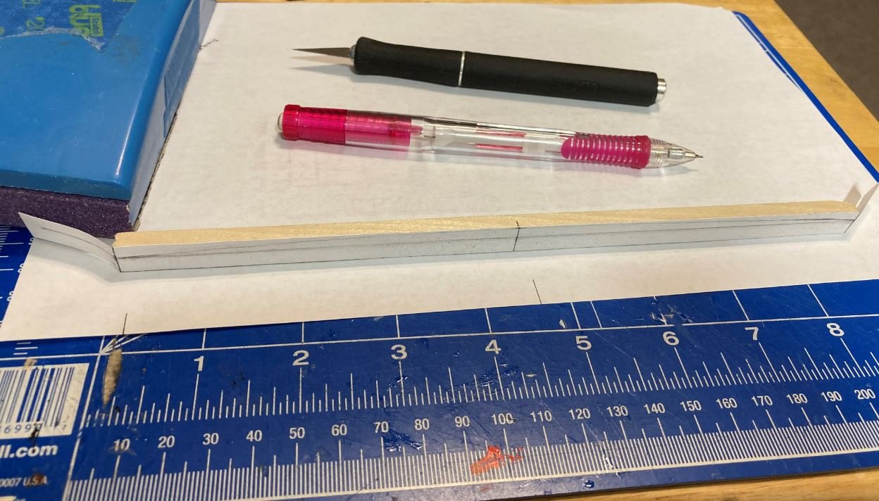
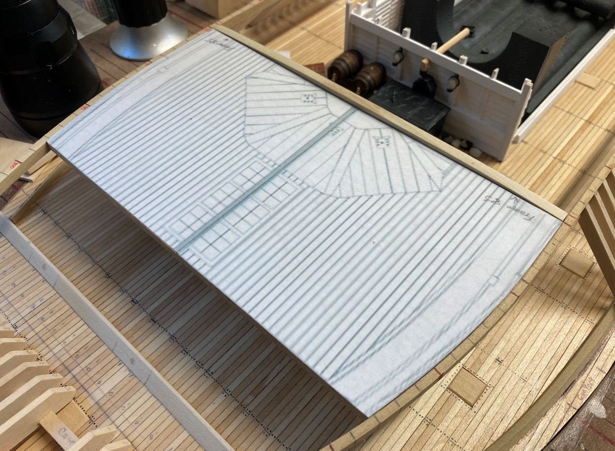
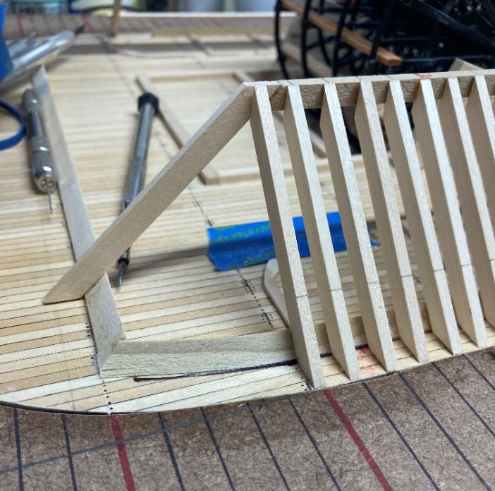
Then the fun began where the top beams started to curve in at the bow. I built up one of the ceiling beams to keep the port and starboard casemate frames equidistant apart while I made the bend in the beams. The ceiling beams have a slight bow to shed the water from the hurricane deck. I calculated these to be about 4mm in rise to the center to give them the correct radius. I glued the pattern to the beams and sanded them down on my disc sander.
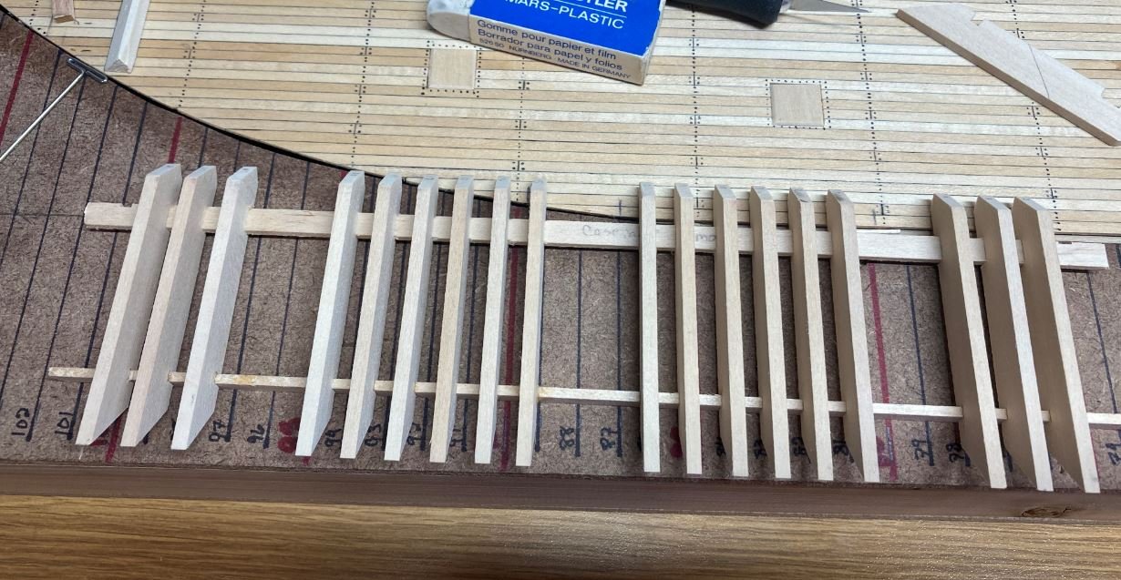
With the first ceiling beam in place, I then cut out a pattern and form to use for a consistent and even bend on the forward frames.
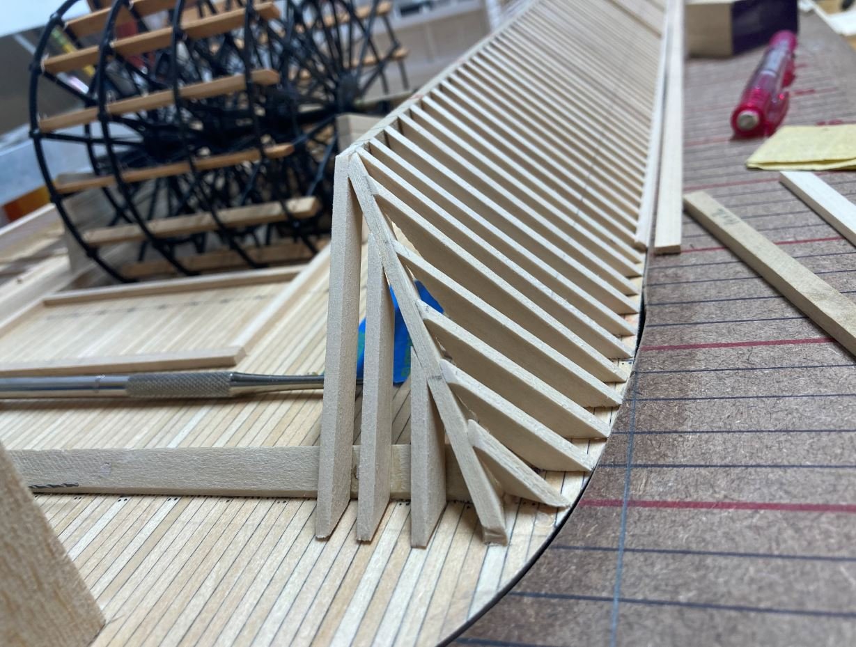
A second and third ceiling beam were added to keep the curve in place, along with the forward casemate frames.
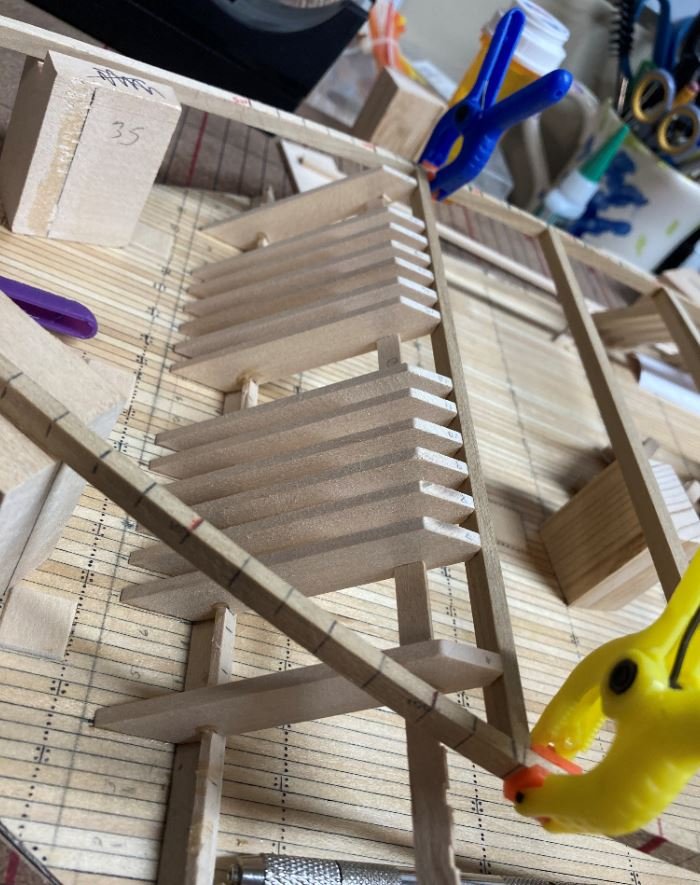
I was having some trouble keeping the top beams from going back to their original form. My attempt at steaming them with a steam iron was not working all that great, not to mention the look the Admiral gave me when she caught me using her iron for something other than what it was intended for. So I drilled some holes through the side beams and into the ends of the ends of the ceiling beams and epoxied some toothpicks into them. I also added a small piece of scrap wood to the bottoms to hold it all together. The scrap wood should be out of the way where it is not seen on the inside.
Once the epoxy was set, I trimmed the top beams and finished out the port and starboard casemate frames to tie into the forward ones.
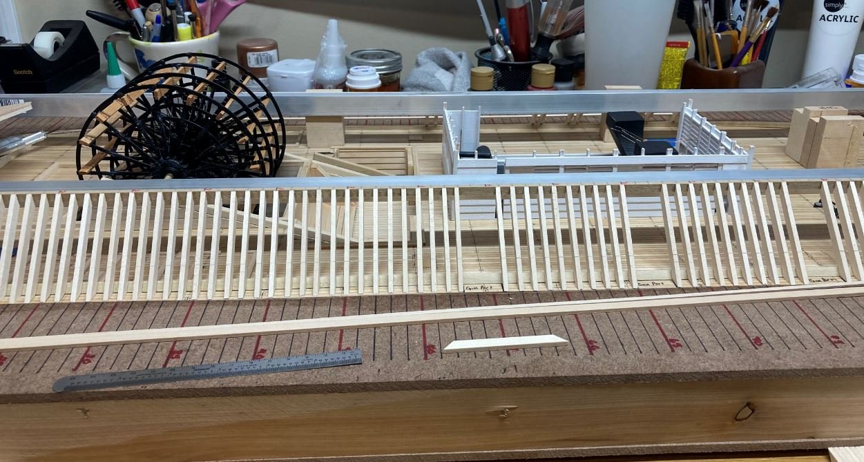
Next I finished out the aft frames. Again, I temp installed a ceiling beam to keep the sides at their proper distance then installed the framing.
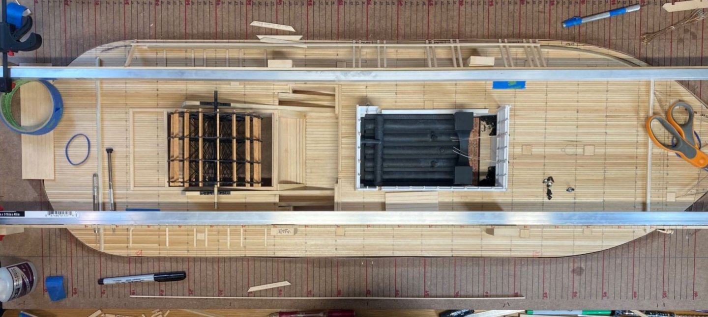
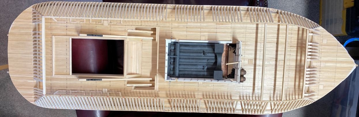
With all the framing in place, I have now removed her from the building frame. This makes it a whole lot easier to work on not having the bulky jig to deal with. Here is where she sits right now. She is starting to come together.
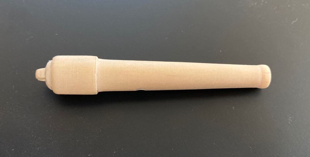
Finally, with the framing completed, I tried my hand at some more wood turning. I wanted to see if I will be able to make my cannons from wood. I think I have the concept down, just not sure if I can make them consistent. Here is my first attempts on the 30lb Parrot Rifle and one of the 32lb Smoothbores. I'd be glad to hear any thoughts on them.
That is all for now. Hopefully I can get more done since the colder weather is starting to set in. Of course the holidays are also around the corner so that may put a delay on some of it. In any case, thank you for looking and all of the kind comments and likes.
-Brian
- KeithAug, dcicero, Nunnehi (Don) and 11 others
-
14
-
3 hours ago, yvesvidal said:
I have resurrected the Emma C Berry by Model Shipways.
Quite the contrast to the sub. Looking forward to watching that build.
-Brian
-
On 11/22/2020 at 3:22 PM, vaddoc said:
Just catching up Brian, the stove came out great. What paint did you use and did you use any primer?
Vaddoc,
Thank you. No primer, I just used an ordinary rattle can of flat black. I then dry brushed the highlights with a gray acrylic and finally coated it it all with satin clear lacquer. I used the same technique on the paddle wheel and boilers. Seems to work fairly well.
-Brian
-
Yves,
I still sit here in amazement at the beauty And detail of this build. So sad to see it end. Can’t wait to see what hits the bench next.
-Brian
- popeye the sailor, yvesvidal, J11 and 6 others
-
9
-
3 hours ago, KeithAug said:
Brian, isn't it annoying when life intrudes.
Great job on the stove, I particularly liked the aluminium tape technique.
Thank you Keith.
I definitely agree, the aluminum tape technique works great for giving wooden parts a metal look and provides an easy way to simulate the rivets, especially after painting. I wish I would have used it on my Chaperone build, it would have given my stacks and boiler a more realistic look. Oh well, all part of the learning experience.
-Brian
- Canute, Keith Black, BETAQDAVE and 2 others
-
5
-
Bob,
Thank you so much for the kind comments.
I started building model ships back in my tweens, graduating to full rigged plastic models in my later teens. For a while I had abandoned ships altogether and moved over to planes (a direct result of serving in the Air Force). It was only until about seven years ago that I got into building the wood ship models. With each build comes new experiences and learning. I look at my first wood build HMB Endeavor, while proud of how it turned out, I still see many flaws and things that I should have, could have, done differently. But, it gives me something look back on and see how my skills have progressed. While I am not in nearly the same league as some of the builders on this site, I’m happy with my results so far. Along with this it’s helped me gain the confidence to tackle a scratch build like this.
In the end though, it's not totally about the end result, but rather how much you enjoyed getting there.
-Brian
- FriedClams, J11, Canute and 2 others
-
5
-
Hello again everyone,
Progress has been a little slow for this update, my focus has been on projects around the house trying to get many of the outside things taken care of while the weather is nice and before it gets cold.
A couple of things that I did get accomplished were the cookstove and some of the lantern wiring. I am still shying away from the engines for some reason, mainly because I still haven't found enough photos of it to get a good representation of them. I had hoped that a friend of mine who was passing through Vicksburg a few days ago could have swung by and taken some pictures for me, but unfortunately the Cairo display and museum are still closed. So for now I'll work on other parts.
So on to the update.
Starting with the cookstove. This was just cobbled together with a few pieces of leftover wood sprues from a previous build (I throw away nothing). I then covered the whole thing in aluminum tape.
The basic form of the stove.
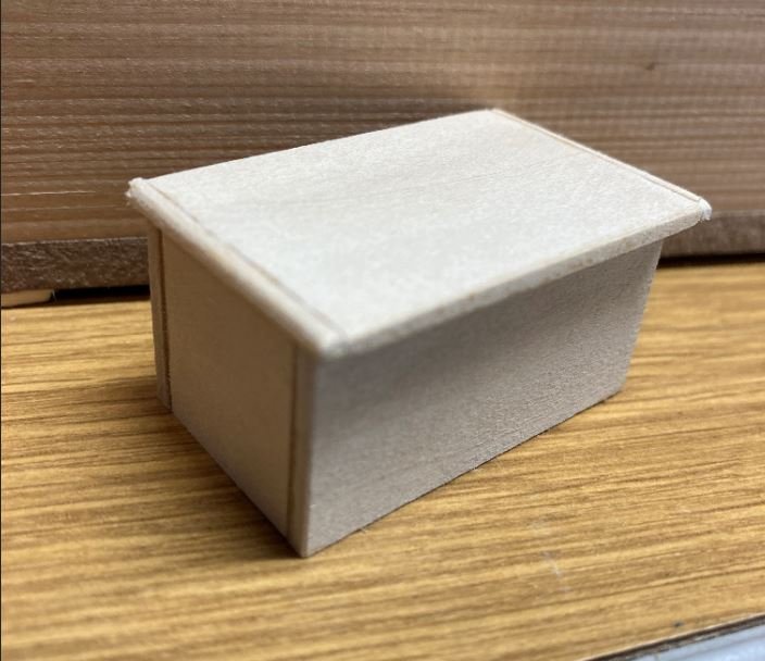
I then covered the box with aluminum tape and scribed the cook plates and top.
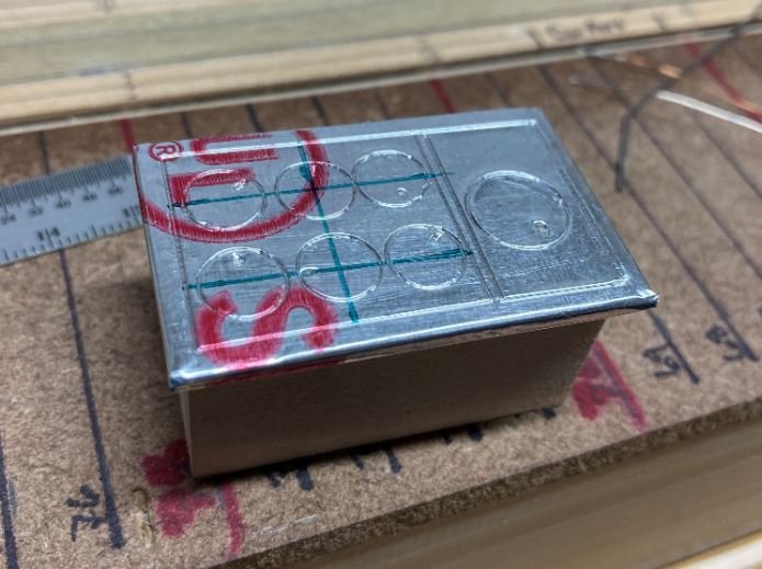
I then added then added the fire doors, hinges and handles.
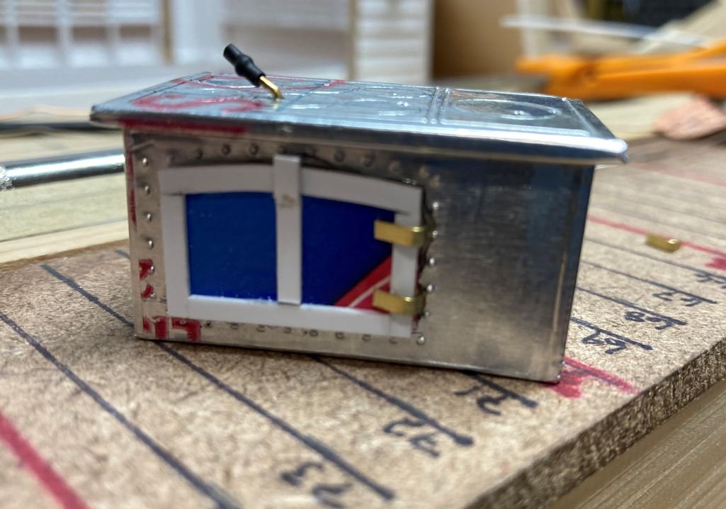
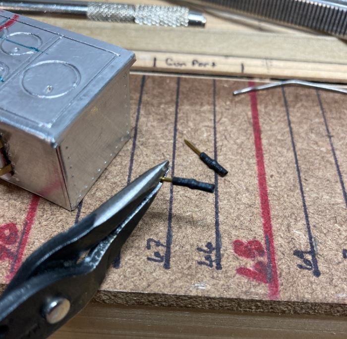
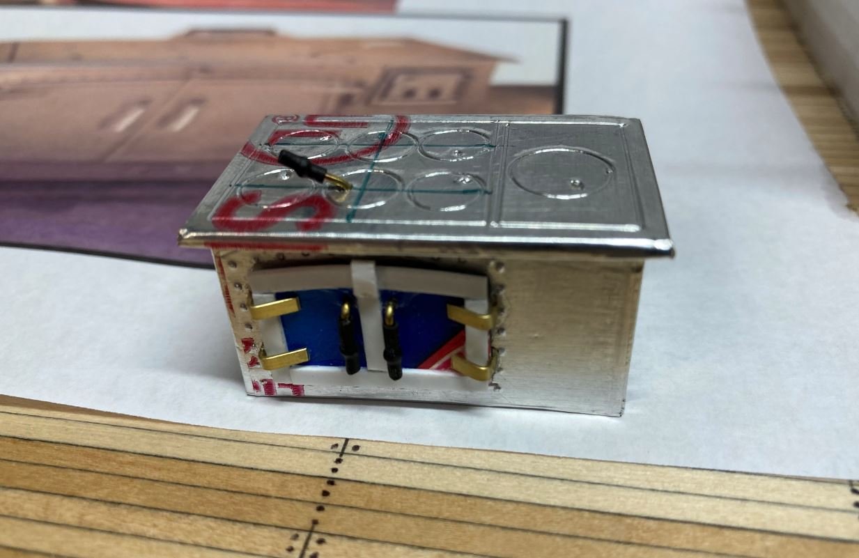
Next I added additional features. Not sure what all these features are, they just added to detail.
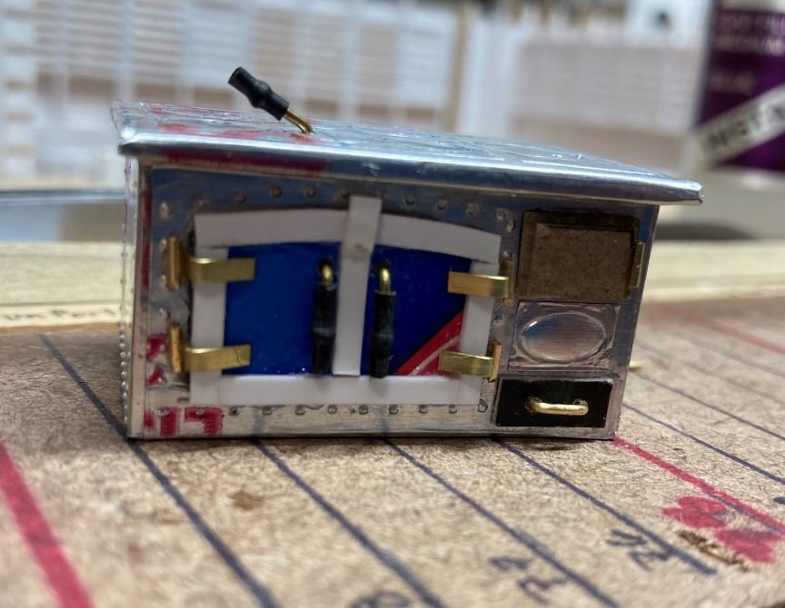
Finally added the chimney flue.
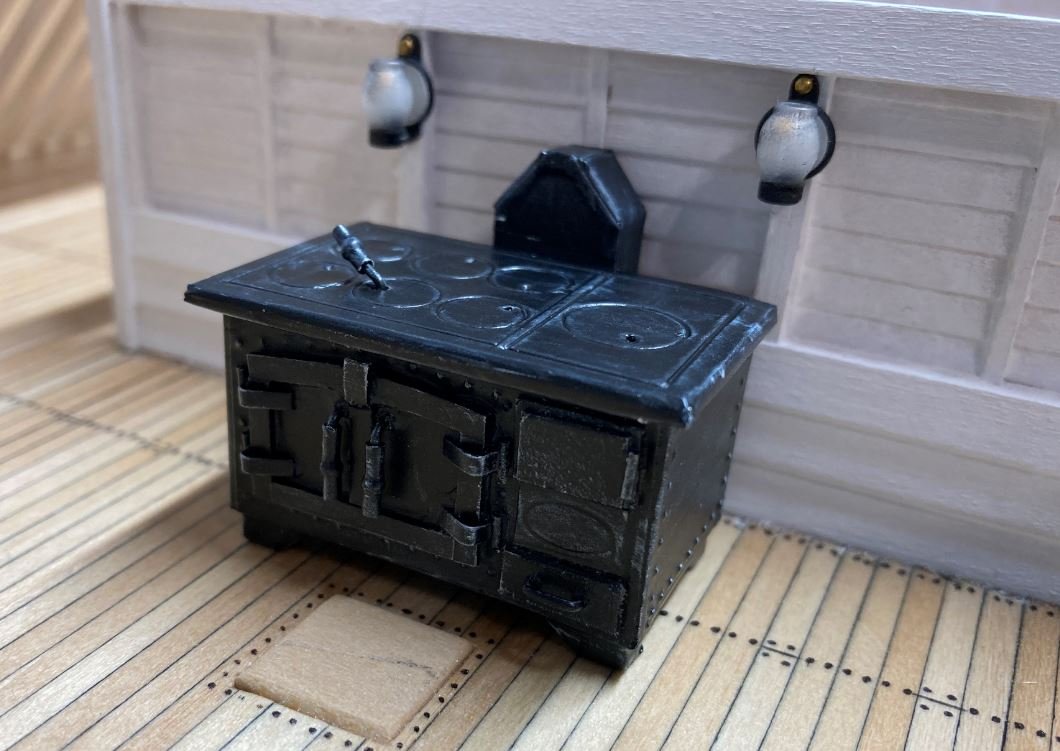
Once the assembly was complete, I gave it a coat of flat black.
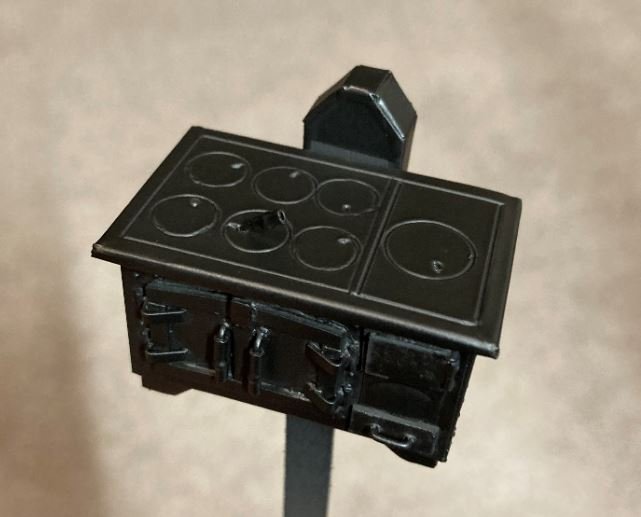
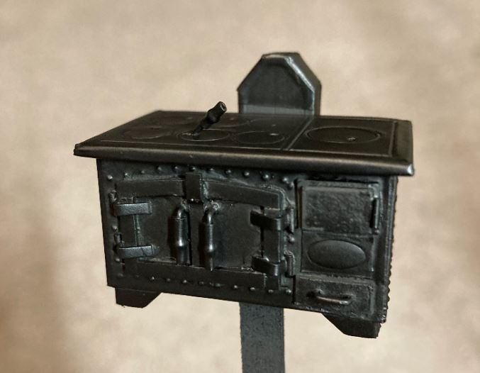
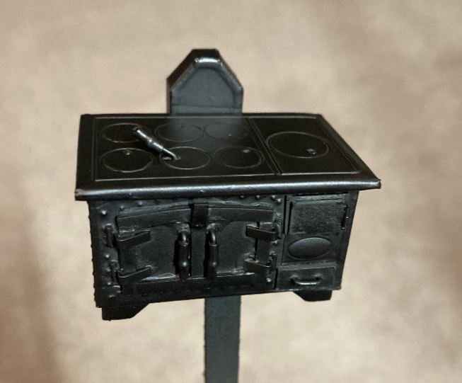
Followed by a dry brushing of light gray paint for highlights and a final coat of clear satin lacquer.
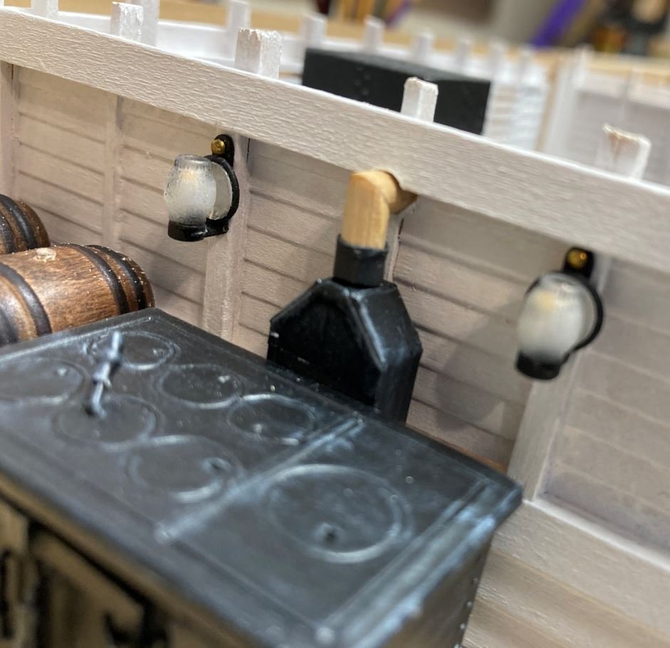
After the stove was completed, I started work on running the wiring for the lanterns. This is some time consuming work, soldering all the connection points. I plan to install about 20 LED's to light major features that will be visible. Some will be disguised as lanterns, others will just be hidden to light other features such as the paddle wheel and engines (if I ever get them built). The central connection point will be hidden under the boiler and I haven't quite figured out where I'm going to put the battery compartment and toggle switch. I still have time though to figure that part out.
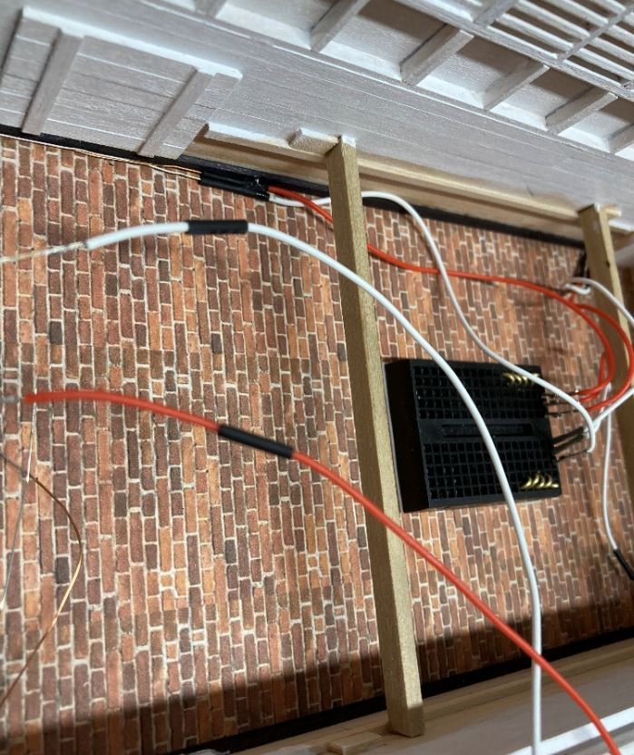
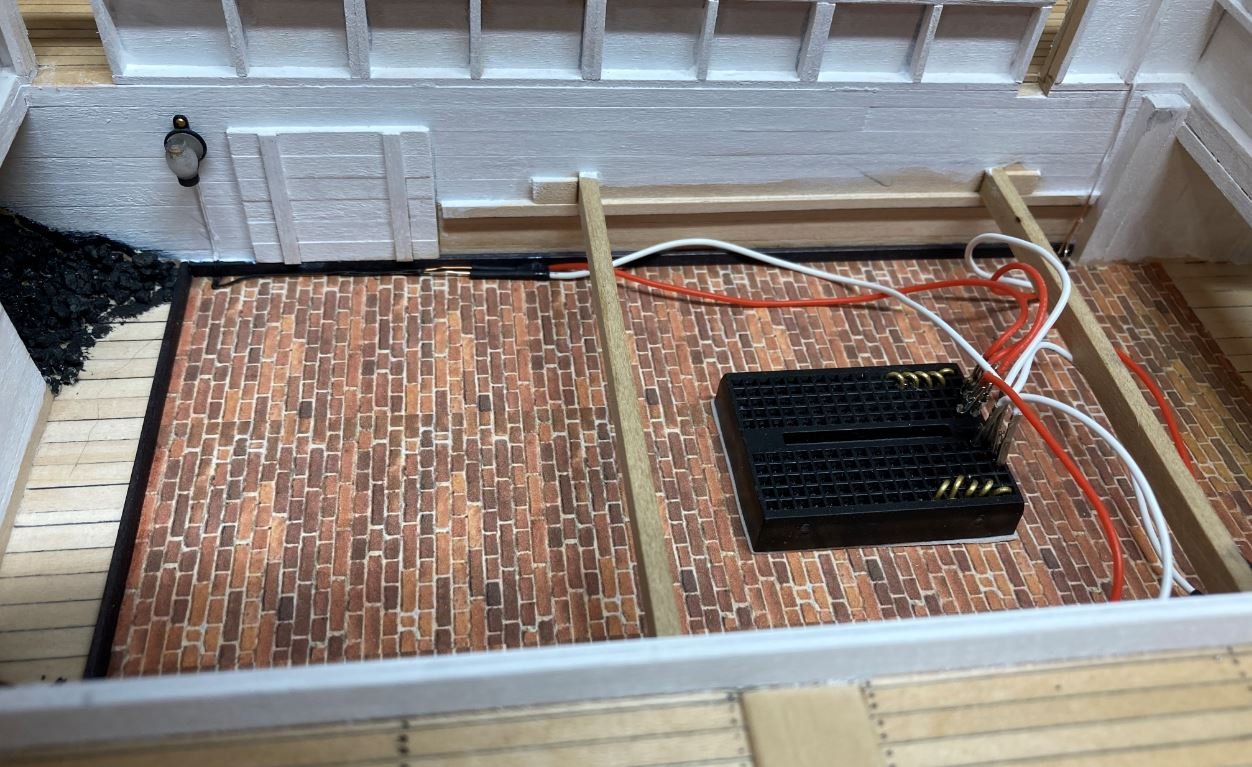
Well that's it for this round. I am going to continue with dressing in the wiring and getting them painted up as well as completing the smokestack for the stove. I think I'm also going to either get started with the cannon carriages or possibly the casemates. Haven't decided just yet.
Until next time, thanks again for all of your encouraging comments and likes.
-Brian
- Keith Black, BETAQDAVE, Moab and 11 others
-
14
-
-
Eric,
Sorry to hear of your woes both with the model and life. Here’s hoping that things get better on both fronts soon. 🥃
I do agree with your decision to go with individually planking the deck, personally I’ve never been a big fan of pre-scribed decks anyway. I do believe the results will be much more life-like and you’ll be more satisfied with the results.
Although this type of boat is way out of my wheelhouse and I’m not real sure how the original ones were built, I do like your idea of building the oar locks. If you are going for more of personal preference and not authenticity, then go with what makes you happy. I think you have said before, this is not going in a museum, so as long as you can get the satisfaction of visitors viewing your work in awe, then go build it as you like.
-Brian
- Cathead, FriedClams and Canute
-
3
-
Yves,
Absolutely stunning build. You are a master of your craft. I have thoroughly enjoyed this build and look forward to your next endeavor. Also, your photos are nothing to balk at at all. They truly do your model justice.
-Brian
-
Greeting everyone,
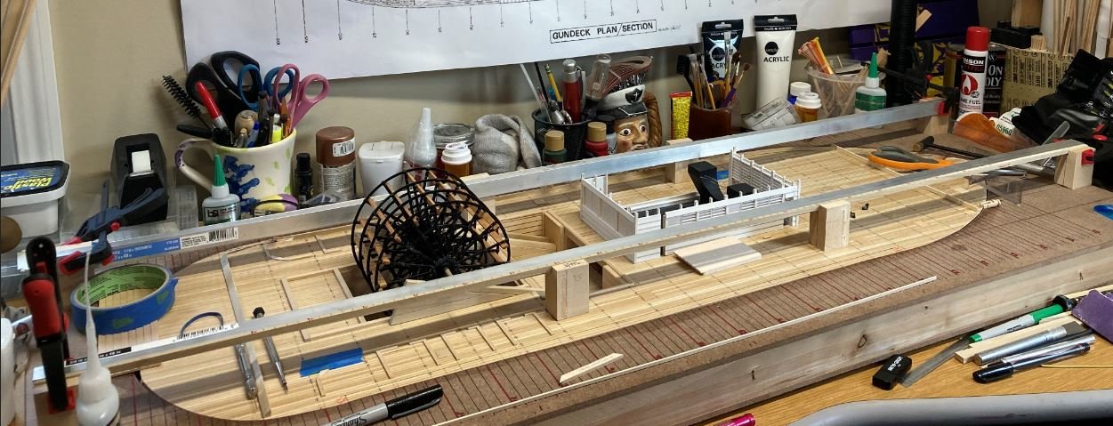
Small update this week. I managed to get the paddle wheel and pillow blocks completed this week.
Here is the wheel assembly painted.
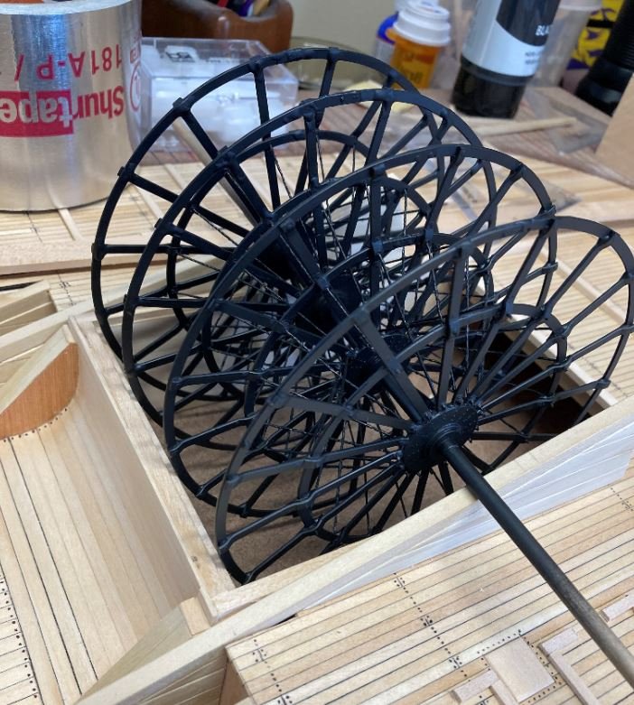
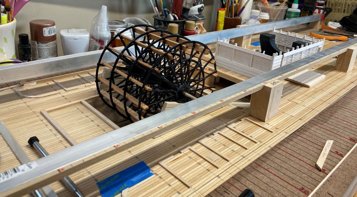
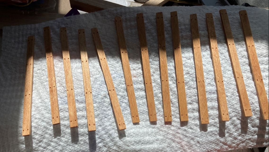
Buckets cut, sanded drilled and stained. I used a mixture of Ipswich Pine and Golden Oak stains for these. I wanted something that would contrast the black ironwork of the wheel assembly, yet not blend in with the rest of the surrounding wood.
First bucket going in.
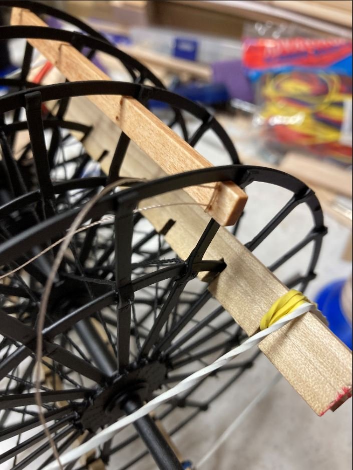
More buckets being installed. I threw together a little jig to hold the assembly while I worked on it. This jig made it a little easier to rotate the wheel, and by inserting a scrap piece of wood between the spokes, kept it from rotating it while I was installing the buckets.

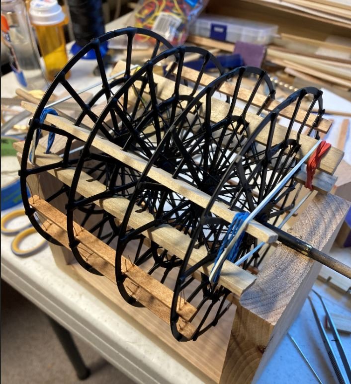
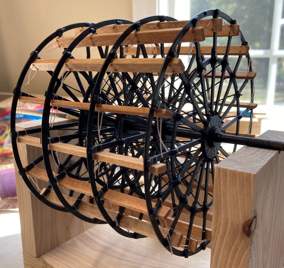
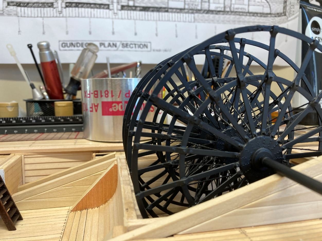
All of the buckets installed and assembly temp installed in the wheel housing.
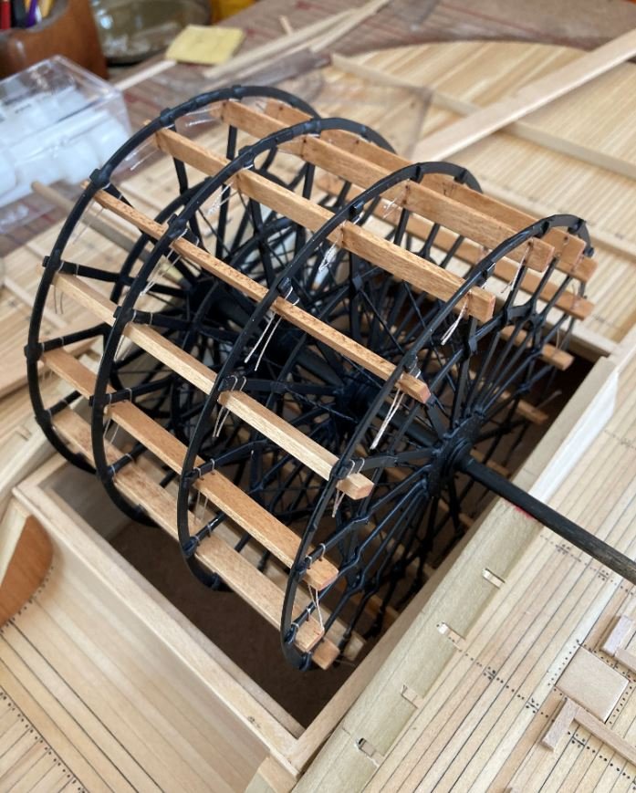
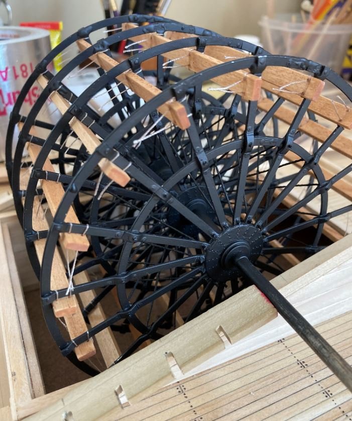
Finally the strings holding the buckets have been trimmed up, a little dry brushing with some light gray to highlight the details of the rivets and a final coat of clear satin and the wheel assembly installed in place.
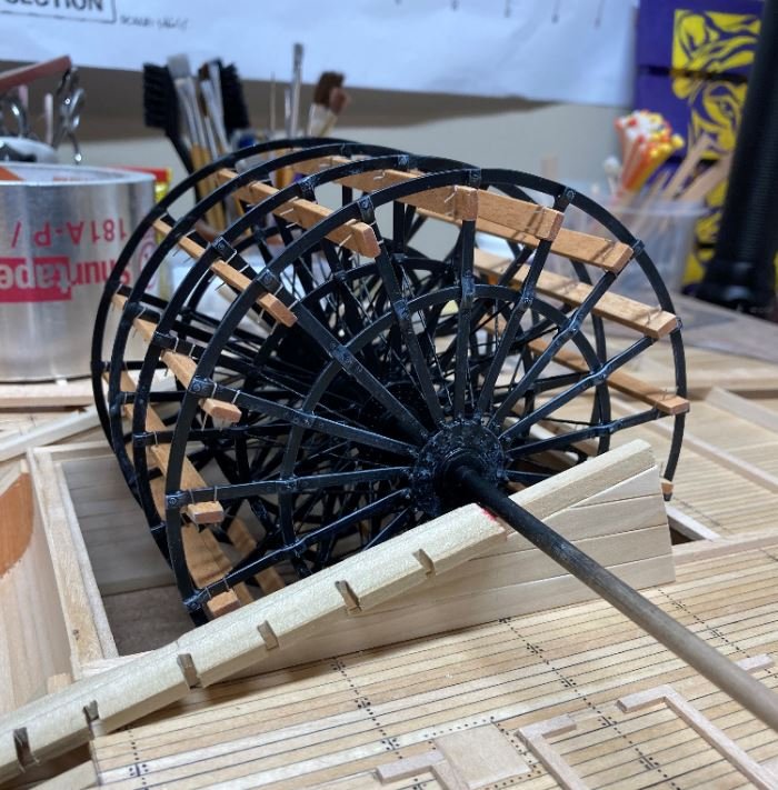
Then it was on to the assembly of the pillow blocks. This part was a piece of cake compared to the paddle wheel.
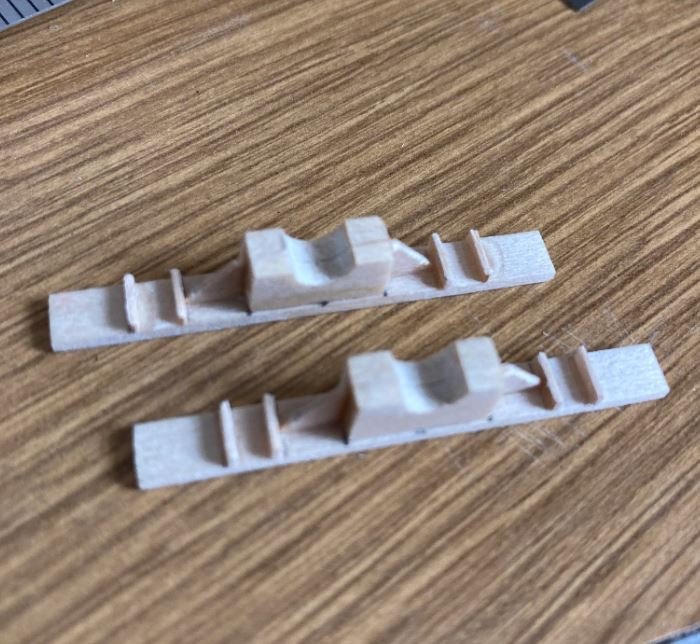
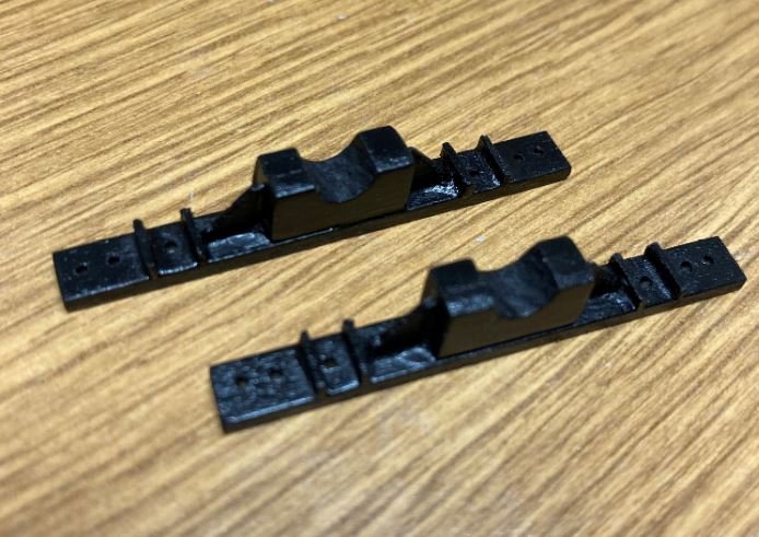
Pillow block installed.
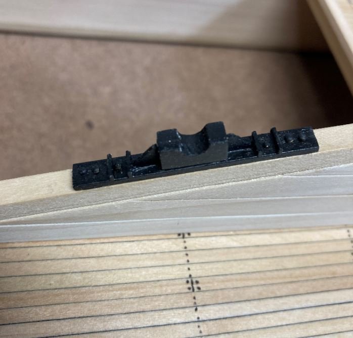
Here is the wheel assembly sitting in the pillow blocks. I still need to make the pillow block caps, I'll have to hunt around for some pieces of brass or aluminum for this part. Something that is the correct width and thickness and will also bend around the shaft, but I'm sure I can come up with something.
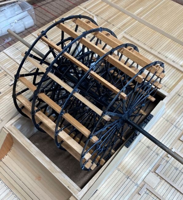
I tried to research on how the buckets were attached to the wheel spokes but couldn't find a whole lot on it. Apparently iron paddle wheels were not the standard back in these days or my search methods were just not up to par. At first I was going to make some simulated iron stirrups to attach them with, but I wasn't sure if this was correct or not. So I went with my gut, and off of the reasoning that the builders of the St. Louis model may have used for theirs in that tying the buckets to the spokes made for ease of quickly changing damaged boards. After all, these were war vessels and I'm sure they took their fair share of damage and in the heat of battle they could not afford to be sitting in the open while maintenance was performed. That and a portion of the paddle wheels on these boats was not protected by the armor plating and could be susceptibly to a fair amount of damage during periods of heavy gun and cannon fire. Just my thoughts, and since there isn't a significant amount of documentation on these, I took my "builders liberties" with it. Also, I think the group building the St. Louis know what they are doing, so I'm going to go with their expertise.
That's all for this update. I think I am going try and revisit the engines this week and see what I can come up with. First go-round just didn't come out right. Hopefully this time will be better. Wish me luck.
As always, thanks for looking and all the likes and kind comments.
-Brian
-
Eric,
Nice job on the figurehead, that’s one of the skills that I have not attempted yet is carving. Not sure that if I gave it a shot that it would resemble a dragon at all, probably look more like a worm.
I’m with Louie on the eye. Protruding would most likely have a better effect.
-Brian
- Cathead, Louie da fly, Canute and 1 other
-
4

Viking longship by Cathead - FINISHED - Dusek - 1:35
in - Kit subjects built Up to and including 1500 AD
Posted
Eric,
Love the look of the deck. It’s coming along nicely. As for the rivets, why not try several techniques on some scrap wood to see how they turn out. At least that way you can see if if you like any of them without risking the looks of your build.
-Brian