


mbp521
-
Posts
989 -
Joined
-
Last visited
Content Type
Profiles
Forums
Gallery
Events
Posts posted by mbp521
-
-
Eric,
Looks good. That should get you going. A few planks along the hull should go a long way to stabilize the hull.
-Brian
- mtaylor, Cathead and FriedClams
-
 3
3
-
Kent,
Welcome aboard, glad to have you following along.
Frisco huh? I’m about 45 due north of you on Lake Texoma.
-Brian
- Canute, Keith Black and mtaylor
-
3
-
Yves,
Thanks for the update. Glad that you are still working on this build. I’m sure you aren’t the only one that gets sidelined by other projects. They do provide a benefit in a way, they help to keep the other projects from becoming stale.
Looking forward to future progress soon.
-Brian
-
12 hours ago, dcicero said:
My pleasure. The Vicksburg Campaign is endlessly fascinating. I also recommend Vicksburg is the Key by Terry Winchell. It’s a good read by a terrific historian. I’ve heard him speak a couple of times and, before reading this book, thought his Triumph and Defeat was one of the best overviews of the campaign.
I’m also a fan of the U.S Army War College Guide to the Vicksburg campaign, but you’ve really got to be interested in this stuff to get through that one!
Dan
Dan,
The Vicksburg Campaign is a fascinating subject as is the American Civil War in general.
Hailing from the Baton Rouge area there was plenty of Civil War history around to study. I remember one of my middle school field trips for Louisiana History was to Port Hudson, site of the last Mississippi River stronghold captured during the Union campaign to control the Mississippi River. Up to this point, this siege was the longest in US Military history (one day longer than the siege on Vicksburg). I do believe this trip was what fostered my interest in the ACW. A couple of years later I went to Vicksburg NMP and that was when I first laid eyes on the USS Cairo. After this trip, my interest in boats and building models of historic ones began and have building them every since. It wasn't until about seven years ago that I caught the wooden model building bug. I started with a couple of cross-sections to get used to the techniques, then on to full rigged ships.
In 2006, on our return trip from my daughter graduation from boot camp at Parris Island we stopped of in Vicksburg to tour the NMP once again. This time I was lot more appreciative of what actually took place there and what the people of Vicksburg must have gone through during this time. Then touring the USS Cairo and it's museum prompted my drive to build a model of her. I believe I mentioned earlier in this build that unfortunately there are no large scale models available of her (that I was able to find), so scratch building her was my only option.
My apologies for the personal history lesson, but you struck on a topic that I have a lot of interest in.
-Brian
- mtaylor, FriedClams, Canute and 2 others
-
5
-
-
14 hours ago, Roger Pellett said:
Brian,
The book is Grant Wins the War: Decision at Vicksburg by James R. Arnold.
Straight military history, well told, adequate maps. After reading I feel that I understand this complex campaign.
Roger
Thanks Roger,
I managed to find a copy of this book on Amazon for $6. It should be here some time next week along with my copy of Alan Bates’ The Western Rivers Steamboat Cyclopedium.
-Brian
- Canute, Keith Black and mtaylor
-
3
-
11 hours ago, Roger Pellett said:
Mounted where they are the rudders would have been ineffective. A better choice would have been to move them inboard where they would have benefited from the fast moving water from the paddle wheel, but that would have posed a structural problem- how to support them.
The inboard, center location of the paddle wheel was likely an attempt to shield it from gunfire.
Roger
Roger,
I definitely agree with you on this one.
My though was that if they moved the paddle wheel aft a few feet and mounted the rudders in front of it, it would probably be more easy to control. This would be in line with the design of the stern wheel packet boats and would also hide the rudders preventing them from being an easy target.
-Brian
- Canute, Keith Black, mtaylor and 1 other
-
4
-
1 hour ago, Keith Black said:
Far North Texas........Denison, Sherman, Gainesville? My son was born in Sherman, at the time we were living in Tioga .
Keith,
Small world. Actually right between Sherman and Gainesville. Small town of Gordonville.
-Brian
- Canute, mtaylor and Keith Black
-
3
-
Gary,
Thank you for the kind comments, glad to have you following along. USS Cairo has long been a fascination of mine and I always wanted to build her. It’s just taken a long time to gain the skills to take on a scratch build like this. Thanks to this forum and all of the helpful members on it, I finally decided to jump on in. I figured that what’s the worse that could happen, someone points out something I did wrong and I have to redo it? Oh well, just hones my skills.
I appreciate the useful info on modeling supplies, I’ll definitely add New England Brownstone to my favorites folder. I’m always on the lookout for good sites to shop from. I have the feeling that if all goes well with this build, it may not be the last one.
-Brian
- Canute, FriedClams, Keith Black and 1 other
-
4
-
3 hours ago, Louie da fly said:
I'd say yes - have a frame. The stabler the shape as you plank, the better off you're likely to be. And better to be safe than sorry - it'd be terrible down the track to regret not having a frame.
Eric,
I'm with Steven on this one. I'd say that given the long slender design of this hull, a frame is the way to go. Why risk it when a little extra work will pay off in the end.
-Brian
- Binho, mtaylor and FriedClams
-
3
-
Eric,
Thinking about it, the printed paper method might just be the right idea. Most of it will be hidden under the boilers anyway. With the exception of the ash pit, I may just do that then shape and paint the ones that will be seen. No sense in going through a big expense for something that won’t really be seen.
-Brian
- Canute, FriedClams, Cathead and 2 others
-
5
-
Thank you Roger.
During my research on these boats I’ve read that they were notoriously hard to control. One reason being the small rudder size and the other being the placement of the paddle wheel in relation to the rudders. These factored in with swift river currents probably made it a task that only seasoned pilots could manage.
By the way, I’m curious as to the name of the book you are referring to. I’m always up for reading up more on Vicksburg and the campaigns of these boats.
-Brian
- Canute, mtaylor, Keith Black and 1 other
-
4
-
Thanks Keith. A little bit of extra work but it sure helps keep everything in line. If I ever do another scratch build, this will be the first thing I build.
-Brian
- FriedClams, Keith Black, Canute and 1 other
-
4
-
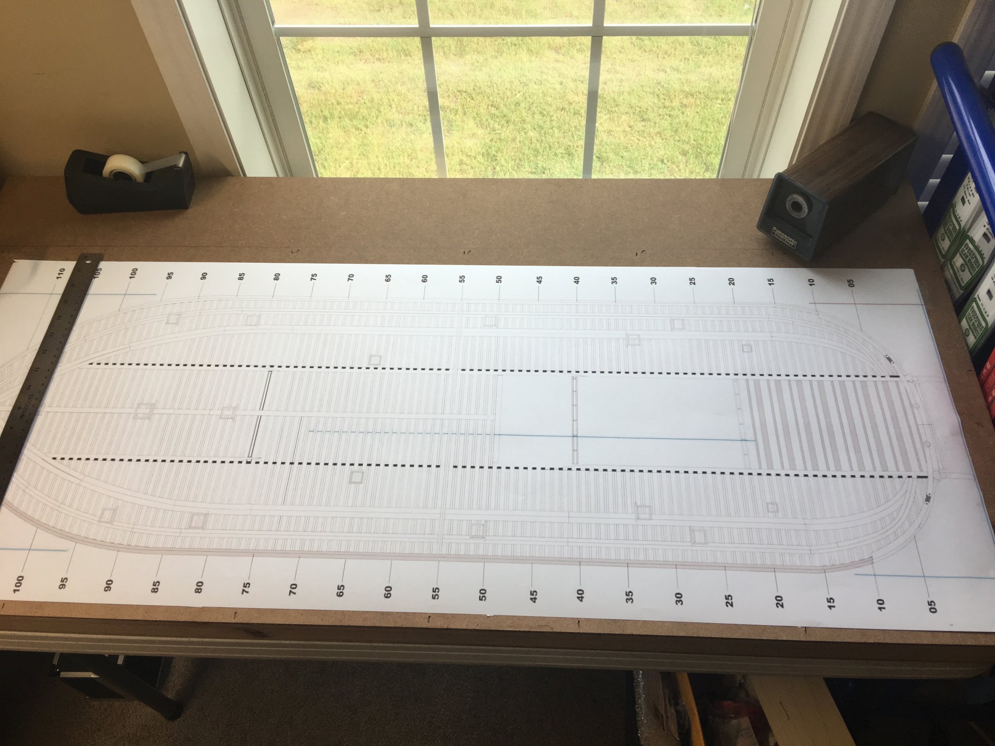
Hello again Everyone,
So I managed to get the build jig set up this past week, and in hindsight I realized that I should have done this from the beginning. It sure makes lining everything up so much easier.
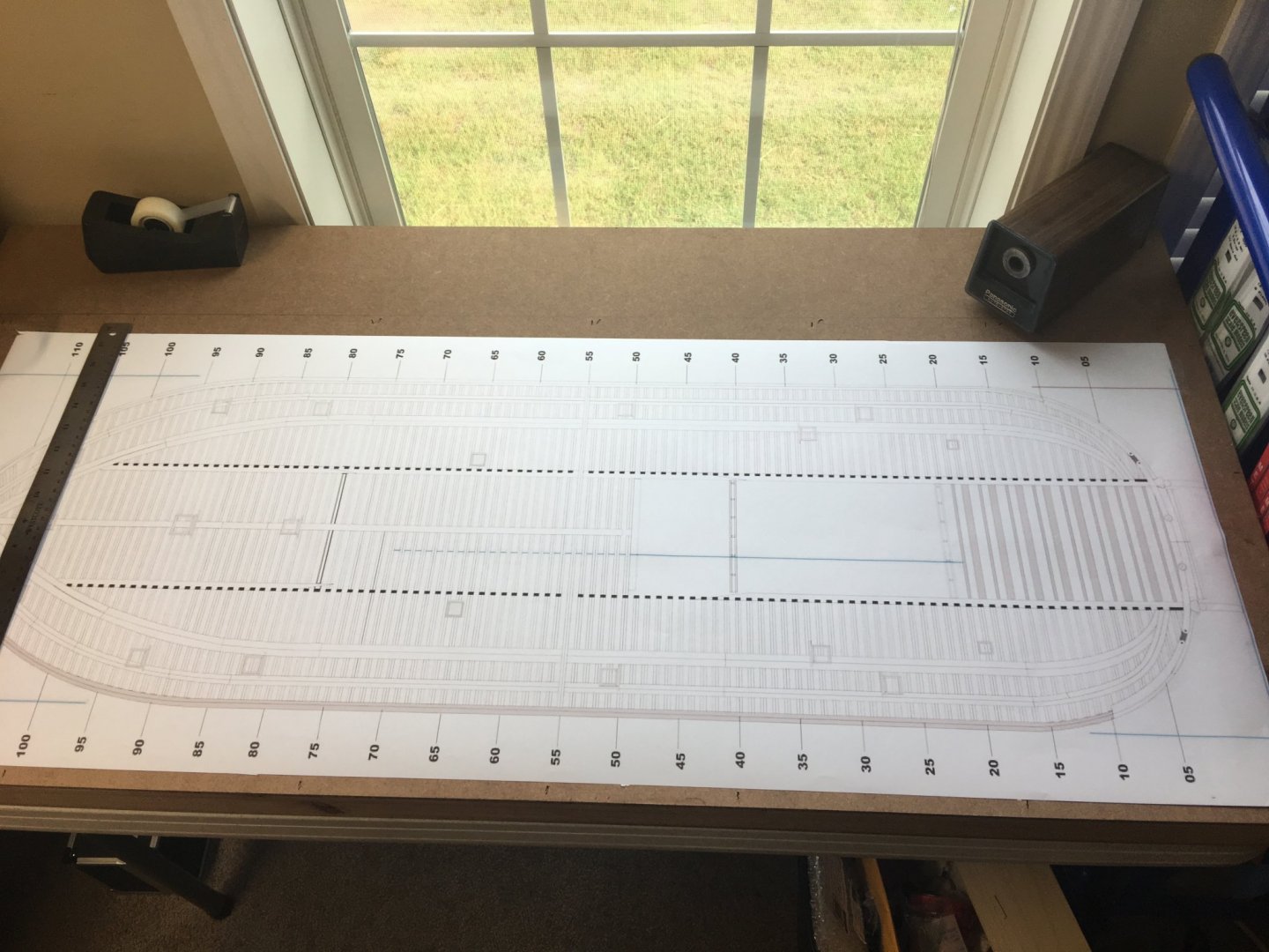
I didn't take any pictures of its construction, I guess I was just excited to get to building it and completely forgot about taking them. Anyway, basic construction was two sheets of 1/4" MDF with 1"x4"s cut to length and sandwiched between them the height of the hull. I then tuned the hull over, traced out it's profile and cut that out. I then lined up the Bob Hill plans (yes, I used these, but first I made sure that the framing stations lined up with the HSR ones and they did perfectly) with the hull opening, taped it in place then marked all of the frames.
This is where I started taking the pictures. Oh, and I went into town and had the scaled plans printed so that I didn't run the risk of the ones I printed and taped together throwing my frame lines out of whack.
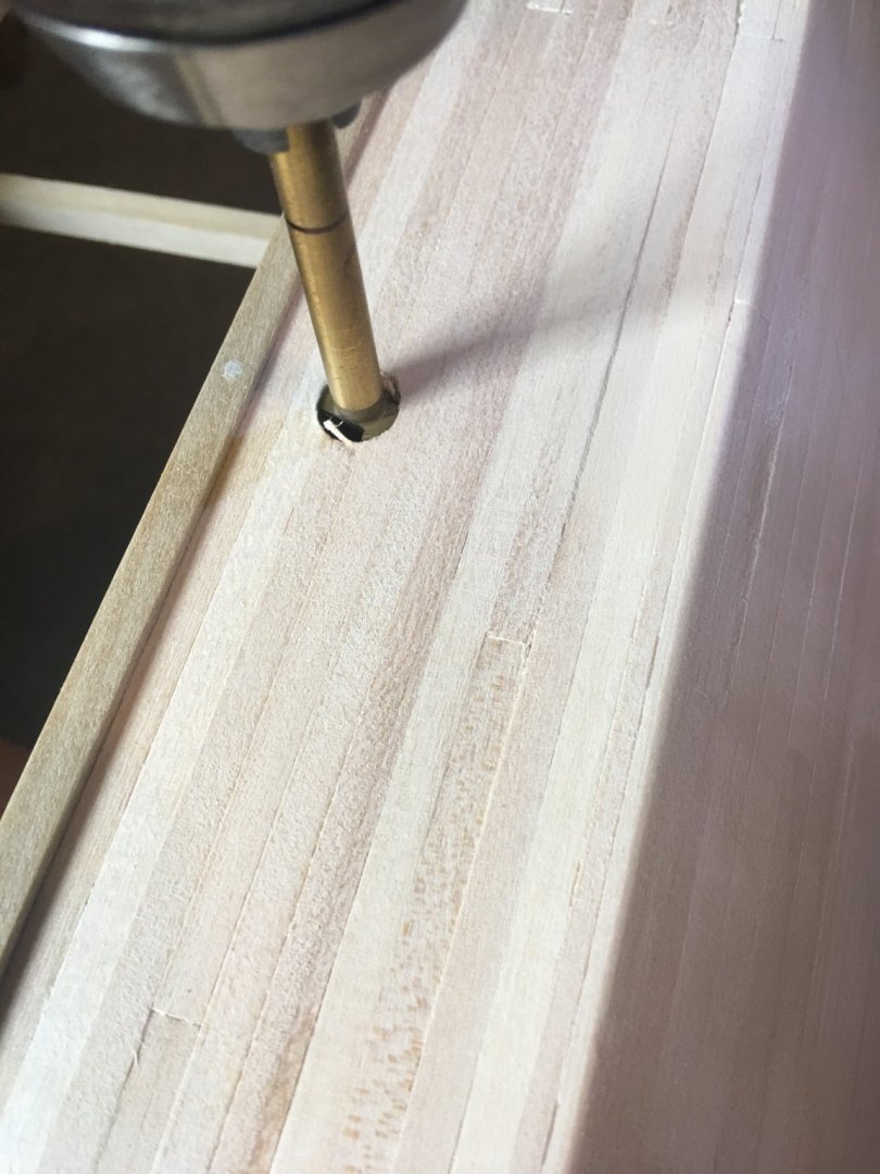
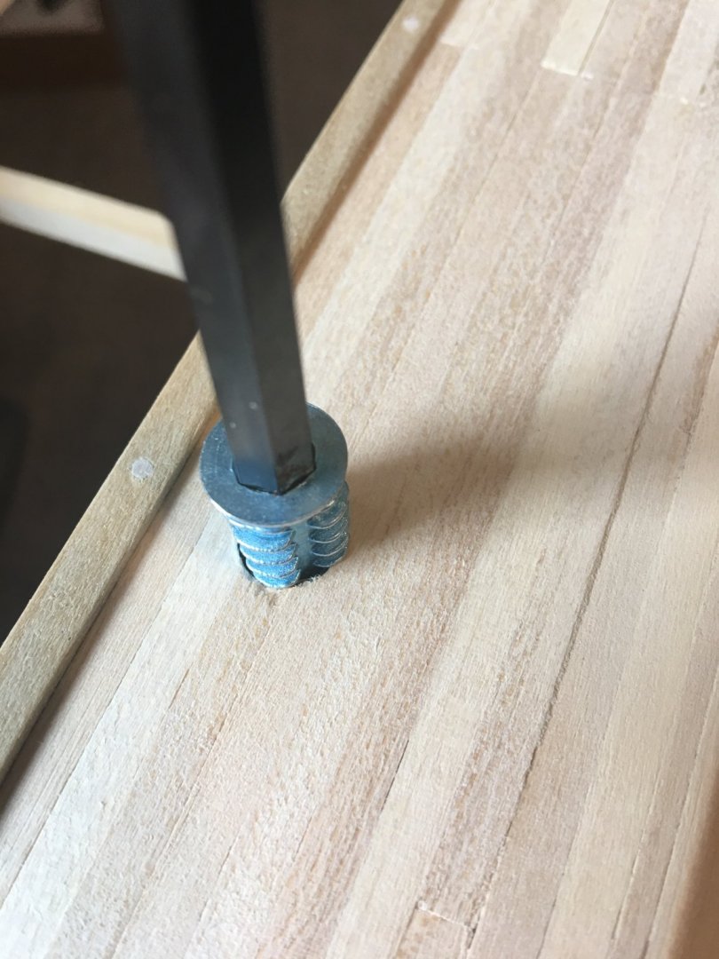
Next I installed the pedestal mounts in the hull so that I could secure it to the jig. I for the mounts I used these 1/4" threaded inserts that you drill the pilot hole and insert with an Allen wrench. These things were pretty cool. I like them better than using T-nuts because if they strip out, you can replace them without tearing apart the model.
Drilling the pilot hole.
Installing the insert.
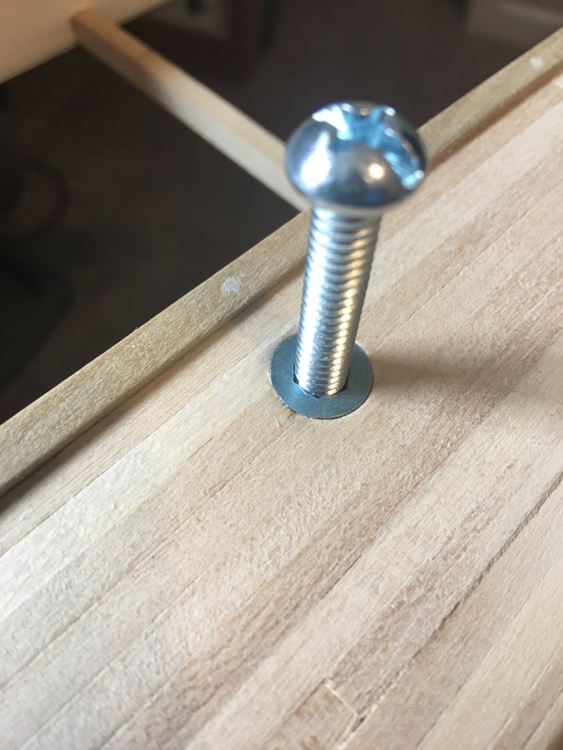
Testing the fit with the temp screws that I am going to use to hold the boat in place while it is in the jig.
And the whole setup in place. The red lines are every fifth frame, as called out on the plans. I then went in and marked all the rest of the frame lines in black so I have a perfect reference for all of the frames. Also, as you can see by my simulated nail lines, The stations gradually migrated out of line with the frame stations. This was where I was having trouble keeping things lined up and prompted me to build the jig. Lesson learned. Luckily most of these won't be seen since they will be hidden by cannons or the Officers Quarters.

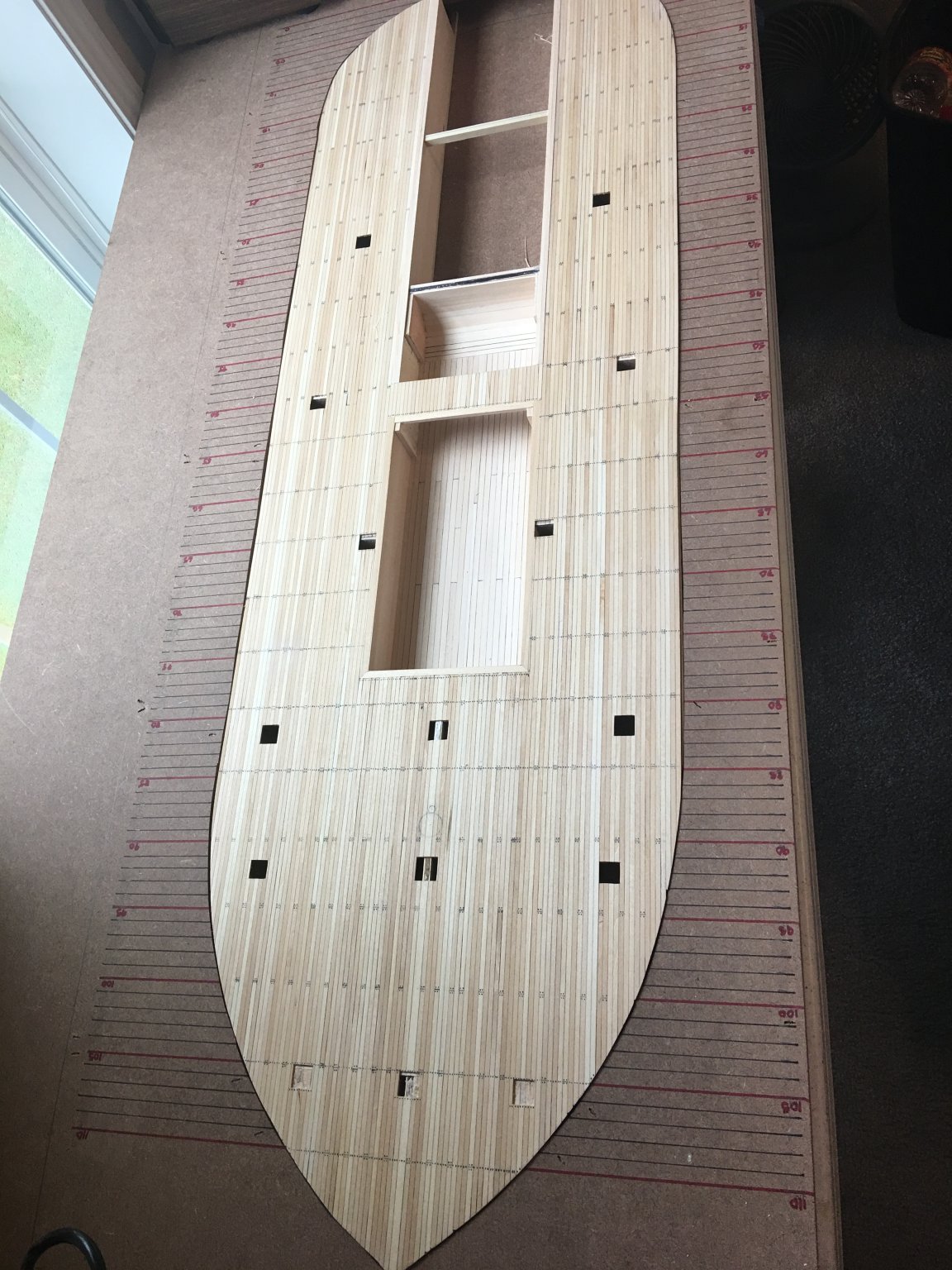
Now that this part is done, it's time to move on to finishing the gun deck framing and planking. First frame in place. And now they can be lined up where they are supposed to be. First frame going in.
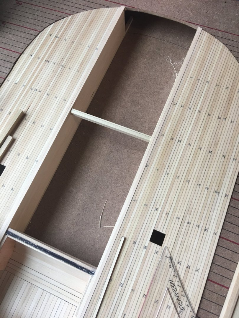
A few more frames in place.
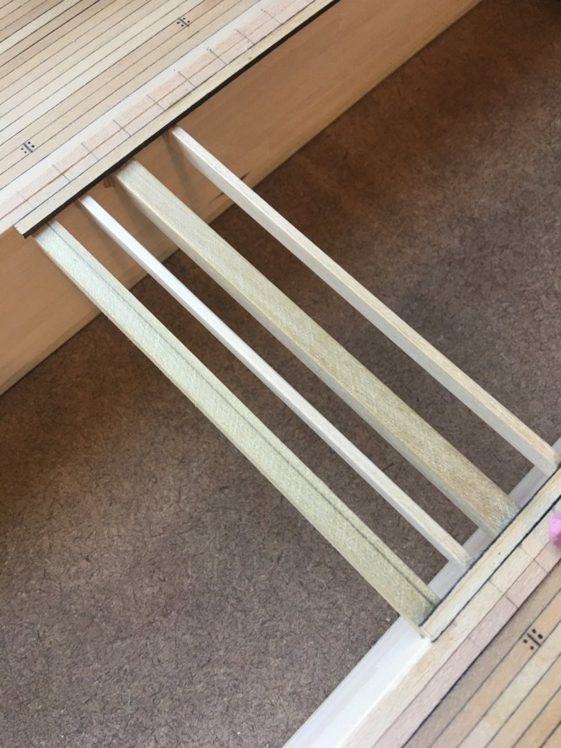
All frames in place. The wider frames have knee braces mounted to their undersides. These will be installed once the boat is removed from the building jig.
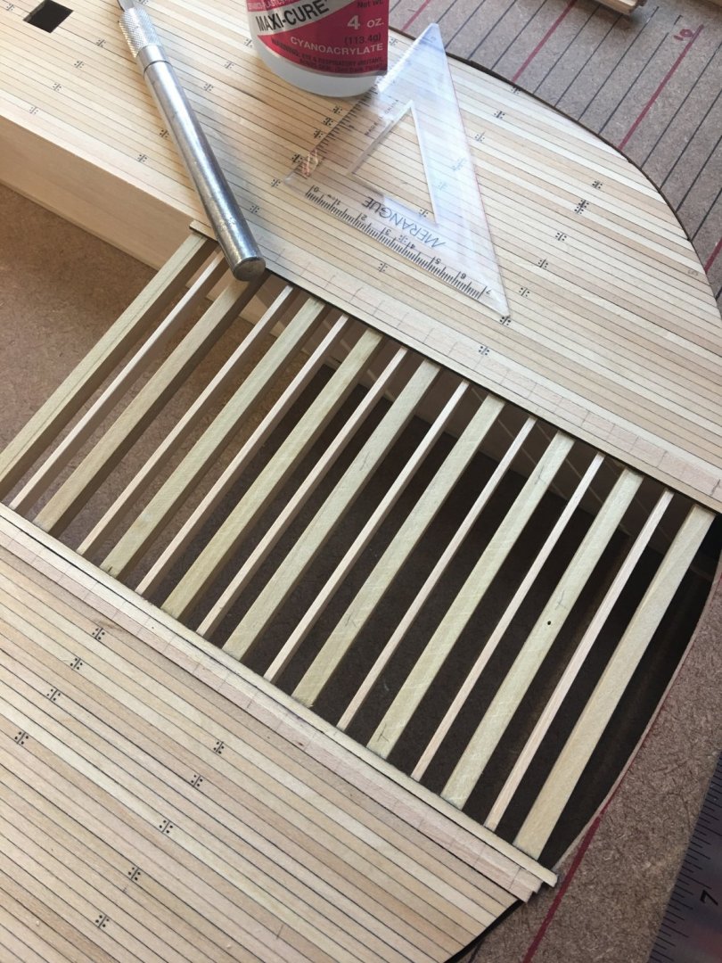
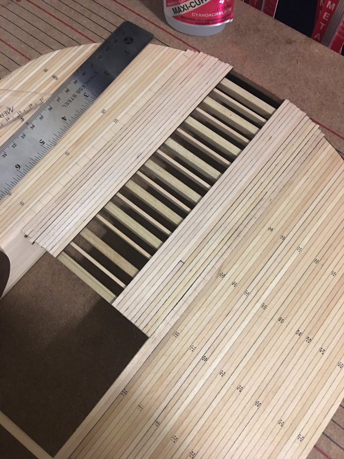
Aft planking going in.

And finally, the engine holds cut out, the deck all sanded and four coats of wipe-on poly applied.
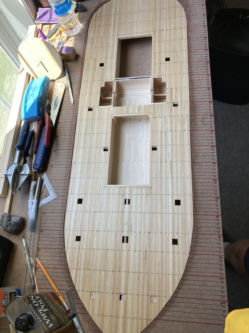
Things ought to start moving along a little better now that I have the build jig as a guide to work off of. I am going to start work this week on the boilers and getting the brickwork laid down in the boiler hold. Haven't quite figured out how I am going to do the bricks yet. I've seen several methods in different builds from powdered mixes to cutting small pieces of wood and painting them up. Not real sure yet, but I am open to any suggestions to other methods used that might be easier.
Anyway, that's all for now. Thanks for looking.
-Brian
-
Great use of the materials on hand.
-Brian
- FriedClams and mtaylor
-
2
-
One can only wonder how odiferous that could get within the closed confines of Iron Clads. I guess eventually you would get used to it.
-Brian
- Keith Black, Canute and mtaylor
-
3
-
Kurt,
Thank you for the information. Out of curiosity, I went to the Howard Museum website looking for the books you referenced. Is there a specific link to them or do you have to email them for information?
-Brian
- mtaylor, Keith Black and Canute
-
3
-
Hello all,
I’d like to pose a question to some of the experts out there about boiler construction.
Since there isn’t a whole lot of documentation on the construction of the City Class Iron Clads, a lot has been open to interpretation and research on the remains of the USS Cairo. Since these boats incorporated a lot of techniques from standard Steamboats I was wondering about how the hulls or decks were protected from the heat of the boilers and fire boxes.
Going by the build of my Chaperon, the boiler was constructed with legs that supported the boiler tubes and there was an ash pit at the front of the fire boxes that I can only assume was brick lined to protect the wooden deck from hot embers that would escape while shoveling coal in. However, there were really no details on what was beneath the boiler tubes.
In one build that I ran across there are pictures of what looks like a shallow pit with a some sort of substrate filled in to keep the heat from the wood planks below it. Was this a standard practice, or were other methods used like brick lining or something else?
One other thought was that the entire boiler assembly was wrapped in asbestos blankets, but again I am not sure of the methods used during this time period and my guess is that whatever materials were readily available at the time were used. And given the fact that the recovered boilers from Cairo didn’t show any evidence of blanketing, this may not have been the case.
I’ve studied the pictures of the USS St. Louis build going on, but it’s hard to make a determination as to what they have come up with, since most of the pictures of the boilers show it off the boat or already installed.
Any suggestions or information would be greatly appreciated.
-Brian
-
-
Patrick,
Coming along nicely. You are definitely right, this hull is so much easier to build and plank than the full rigged ships.
-Brian
-
Tim,
Thanks for the update. Things are coming along. This is an absolutely beautiful build.
I recently started work on my scratch built USS Cairo and have been using this build as a guide. Y’alls research on this really helps answer many of the questions and roadblocks that I have been running into trying to get it right.
-Brian
- Canute, johnhoward, J11 and 2 others
-
5
-
Eric,
I agree with your assumption, the slots do not seem to be cut square. Of course with all of the kits I have built all of the parts we cut just perfectly so that everything lines up just right. (Cough, cough).
Seriously though, you are right on track with adjusting the slots to enable the centerline of the deck to line up with the keel. None of this will be seen when the planking is in place.
-Brian
- Cathead, FriedClams and mtaylor
-
3
-
Dafi,
Its simply amazing at the amount of detail you put in such a tiny space. Beautiful work.
-Brian
- mtaylor, dafi, mort stoll and 1 other
-
4
-
4 hours ago, Keith Black said:
Looks very nice for having to work in such close quarters.
Thank you Keith. At 1:48 scale there is actually plenty of room to work in the hold. Although, once the boiler is installed it’ll be tight quarters though.
-Brian
- mtaylor, Canute and Keith Black
-
3


USS Cairo 1862 by MPB521 – FINISHED - Scale 1:48 - American Civil War Ironclad - First Scratch Build
in - Build logs for subjects built 1851 - 1900
Posted
Dan,
Thank you for the words of encouragement, and I hope to one day follow your build of the Cairo.
You hit the nail on the head with this one, there was some serious experimentation going on with these boats. Given the fact that they just had 100 days to provide seven ships, there had to be major trial and error going on.
Just a couple of examples would be, like one of our previous discussions in this log, the rudder placement and the lack of control of these boats. While the design of these boats was based on the standard stern wheel steamers, many alterations were made to try and protect the mechanical features from enemy fire like moving the paddle wheel forward and under the structure, armor plating etc. I’m sure the builders didn’t have much time for test runs and left it to the Army for shakedown testing.
Another example would be the armament. These boats originally just had flat armor plating on the front, aft and sides (as well as the pilot house) when they left the shipyards. The function of the side plating was just to protect the boilers and that was about it. The crews felt this was not enough and came back and placed the additional armor forward and aft of the side plates using salvaged railroad irons. This holds true for Cairo, I’m not 100% sure of her sister ships. It’s really hard to tell from the old photographs if they all had this additional armor and I have not done extensive research on the other six to be sure. Through my reading though, there were many alterations done to them over time, unfortunately Cairo’s life span wasn’t long enough to get the chance to see many of these alterations.
-Brian