
HOLIDAY DONATION DRIVE - SUPPORT MSW - DO YOUR PART TO KEEP THIS GREAT FORUM GOING!
×


gjdale
-
Posts
4,888 -
Joined
-
Last visited
Content Type
Profiles
Forums
Gallery
Events
Everything posted by gjdale
-
 Curse you Mark - I’ve just ordered a copy! 😉
 -
Byrnes Sander or saw, that is the Question?
gjdale replied to Nirvana's topic in Modeling tools and Workshop Equipment
Love your thinking Per! 👍 -
Your rebuild/repair efforts are really paying off Kevin. Don’t know what to advise on the colour scheme. I kinda like the original but you’re the Captain as they say.
- 273 replies
-
- 2
-

-
- panart
- amerigo vespucci
- (and 1 more)
-
Byrnes Sander or saw, that is the Question?
gjdale replied to Nirvana's topic in Modeling tools and Workshop Equipment
If you didn’t already have a saw, I’d say go for the saw, but as you have a Proxxon one that can do the same function (albeit not as nicely), then perhaps the disc sander would be higher priority as it fills a gap in your arsenal? To be honest, I’d say the disc sander is probably the most used of the power tools for me. -
Byrne's saw accessories question..
gjdale replied to CPDDET's topic in Modeling tools and Workshop Equipment
I’ve been watching a series of YouTube tutorials on machining with lathe and mill by Blondiehacks, recommended by someone else here (Greg Herbert (DVM) if I recall correctly). As well as being excellent tutorials, she has a great mantra around safety. She often says something along the lines of “always remember, these machines are actively trying to murder you - don’t let them!” Good advice me thinks! -
Congratulations on completing a another BE masterpiece. I love the addition of the figures on this one - they really add another dimension to the finished article.
- 195 replies
-
- 1
-
-
- lady eleanor
- vanguard models
- (and 1 more)
-
Well done Bob - looks great! I’m continuing with my own painting trials too.
-
There is quite a mix of metal and plastic, but very little glue is used. Most fastening is done with bolts/screws. The challenge is getting things to align properly, ‘cause they rarely do straight up. Also, pre-drilled holes are invariably too small and need to be opened up to avoid cracking plastic parts. Then there is the inevitable modification required to make things actually fit - eg melting bolt heads down into the plastic frame so that they don’t interfere with subsequent fitting. Hope to have an update to the build this weekend - have been experimenting with paint of late.
-
It’s been worth the wait Mark - looking very nice.
-
Good news Richard - just be prepared for shipping to take around 6 - 8 weeks instead of the usual 2 weeks. It will get here - eventually.
-
Richard, Check out Chuck’s offerings in the Syren Ship Model shop: https://syrenshipmodelcompany.com/turned-brass-cannon.php Also, Chris Watton is developing some for his Vanguard Models range, though I don’t think they are ready for sale/distribution just yet.
-
Welcome home Dave - we left the light on for you.😊
-
Well done Dave - that looks great. You can be proud of this build!
- 51 replies
-
- 3
-
-
- miss unlimited
- dumas
- (and 1 more)
-
Sopwith Camel by rayschilke - Model Airways - 1/16 - WOOD
gjdale replied to rayschilke's topic in Non-ship/categorised builds
I’m pulling up a chair too. I’ve had this kit in my stash for a few years now - one day..... You’ve made a nice start Ray. -
I like this little model, so I’ll pull up a chair and follow along. Looks like you are off to a good start.
-
Congratulations David on completing a really fine model. You can be justifiably proud of your achievement - truly lovely work.
-
Wow, thanks for all the nice comments folks! And thanks Ric for the advice on fitting tyres - I’ll remember that for the next one - or three! As for painting the wheels, I know you are right but I just prefer the look of the chrome. Bob, the short answer is yes. What I did was within each folder, I selected all the individual files, right clicked and selected “create PDF”. I’m on a Mac, so not sure if this is the same procedure for Windows, but there should be a similar function. This creates a single PDF file within each folder with all of the photos for that folder within it. You can scroll through each page within that file. The original files remain as they were, so you’re not changing them - just adding a new file that is easier to work with. I have also printed each PDF file as I have gone, and then wire bound each of these into a booklet (I have a wire binding machine for my business stuff). It’s an expensive option in terms of printer ink, paper and binding supplies, but I prefer working with a hard copy on the workbench - I just find it easier to flick back and forth when I need to - and I need to a lot!!! It also means I can sit and study each section away from the computer.
-
Thanks Bob, Yes, I’ve heard nightmare stories about the wheels being the make or break point for some builders. To be honest, without Paul Koo’s guidance on the “easy” way to build them, I’d be lost. The steering wheel is walnut - they offer several different choices of wood but I liked this one to go with my walnut dash. All of Model Motorcars aftermarket parts are first class - well designed, well made - and very expensive!!! And I have to pay exorbitant shipping rates on top of that, not to mention the unfavourable exchange rate at the moment. I’ve been very selective about what I’ve bought for this model. Who knows, I may end up buying more for the next one - it’s kind of addictive! Make sure you do a thorough inventory of your kit box too Bob, and use Paul’s DVD to help you identify parts. If you are missing anything, chances are that Paul will be able to offer a replacement at very reasonable prices. He also includes a series of photographs on his DVD to show you how to pack the parts back into the box afterwards - trust me, you will need that!
-
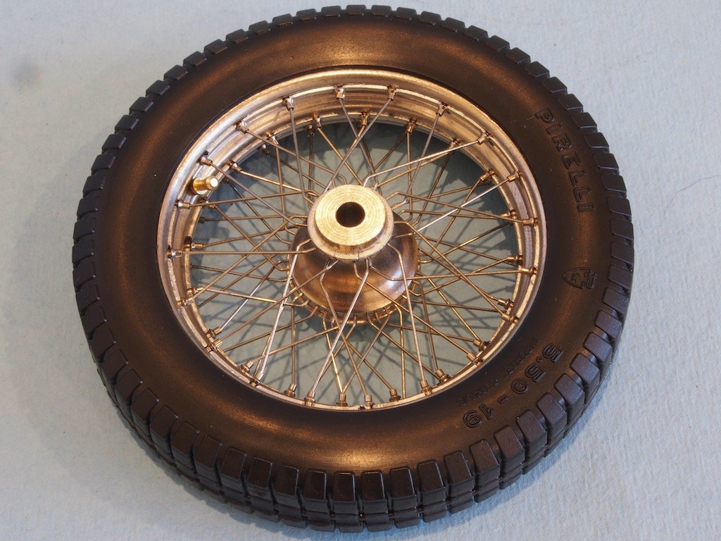
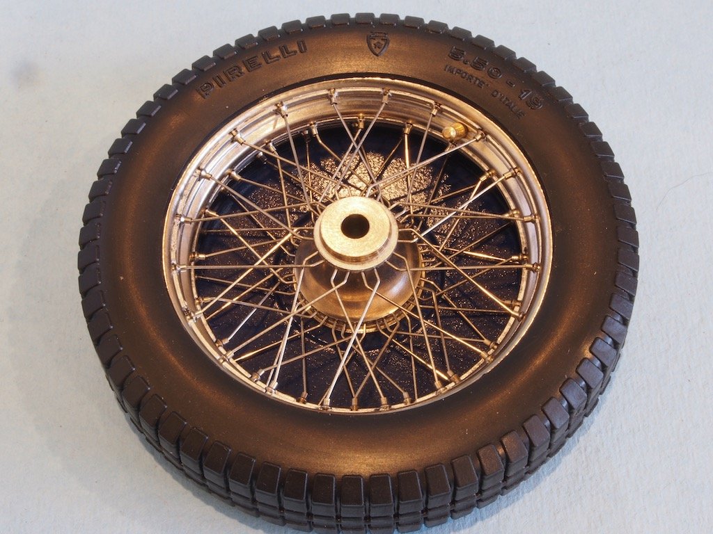
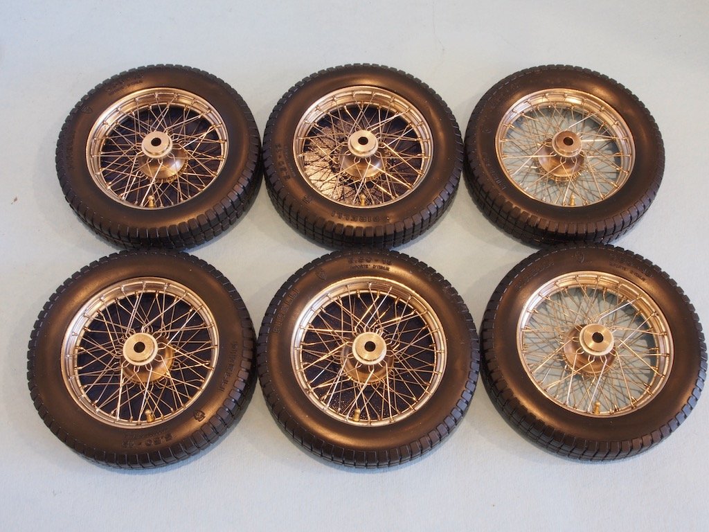
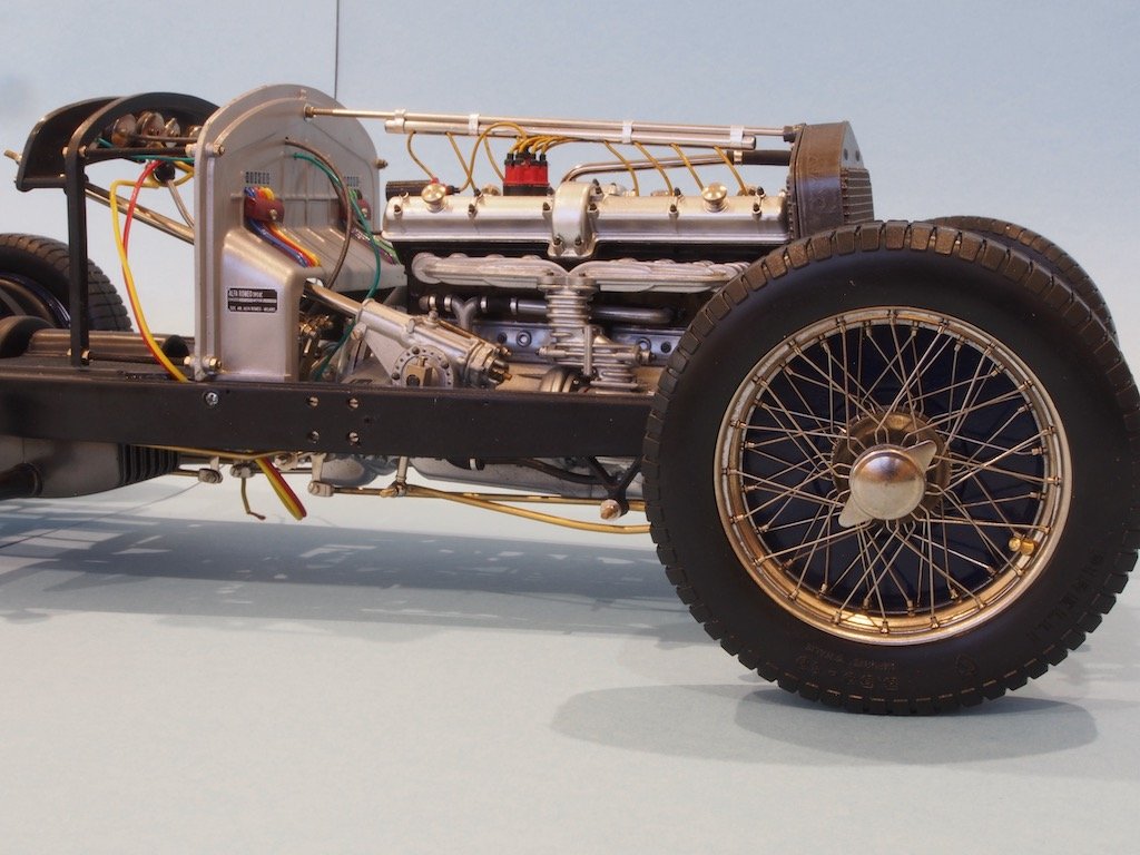
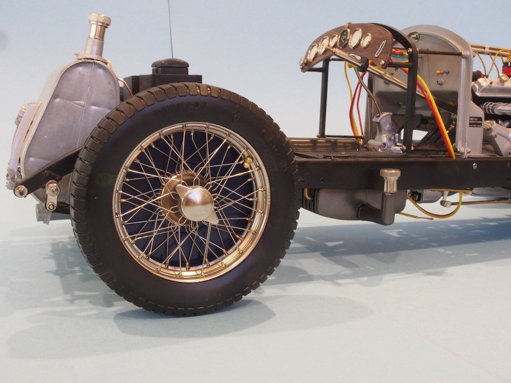
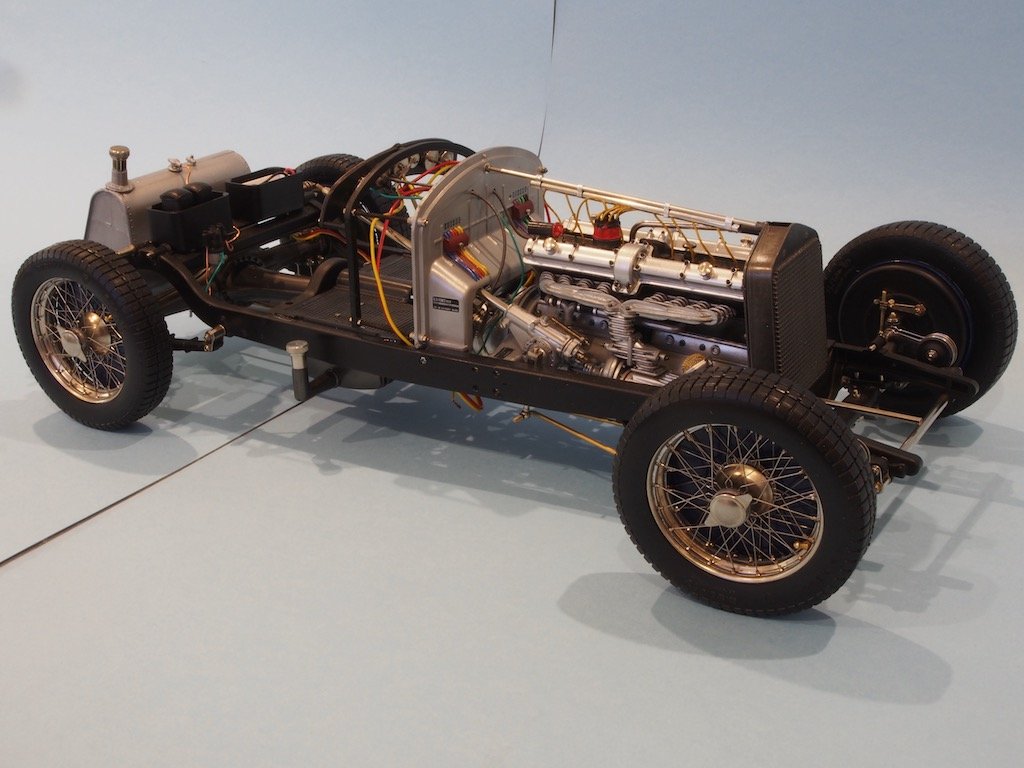
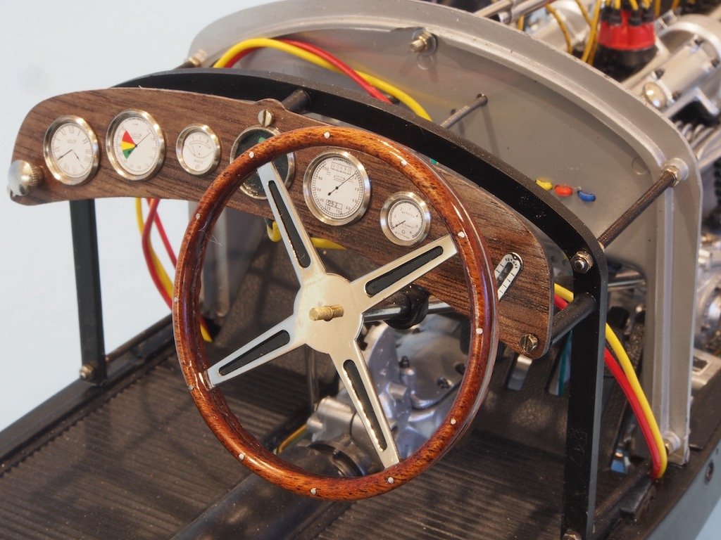
The Wire Wheels - continued Once the glue had cured, the screws from both outer metal rings were removed and the tyres installed. Getting the tyres on was quite a challenge, involving considerable force, the use of a large flat bladed screwdriver, and some very colourful language! Eventually we got there. The brake drums were then attached to the inside of the four main wheels, with the two spare wheels being left “clean”. The brake drums were painted a deep blue, which will match the body fender colour later. Here is the complete set of six wheels – about a week’s work to complete! And here are a couple of shots of the wheels temporarily in situ: I also took delivery this week of a replacement steering wheel. This is an aftermarket component from Model Motorcars – quite expensive but I think makes a huge difference and complements my walnut dashboard nicely. Here it is just temporarily in place for now: That completes this phase of assembly. Next up is the body work….
- 224 replies
-
- 17
-
-
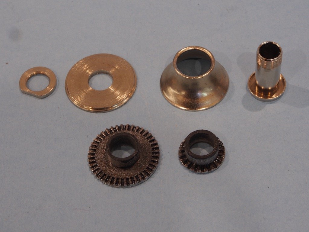
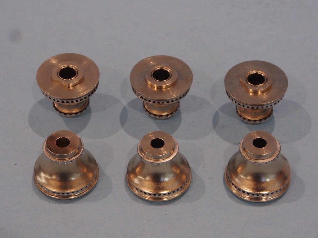
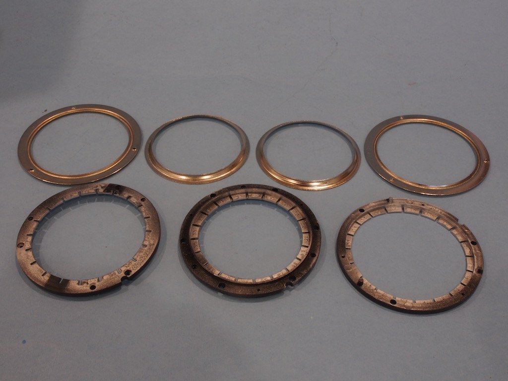
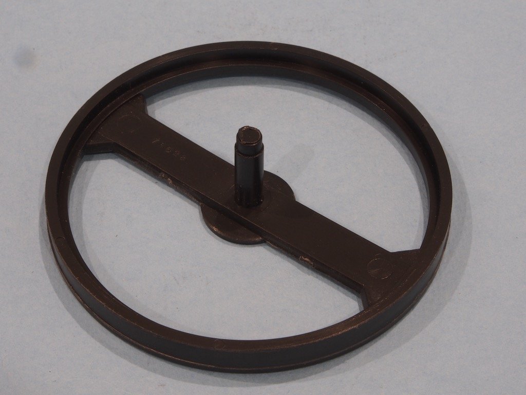
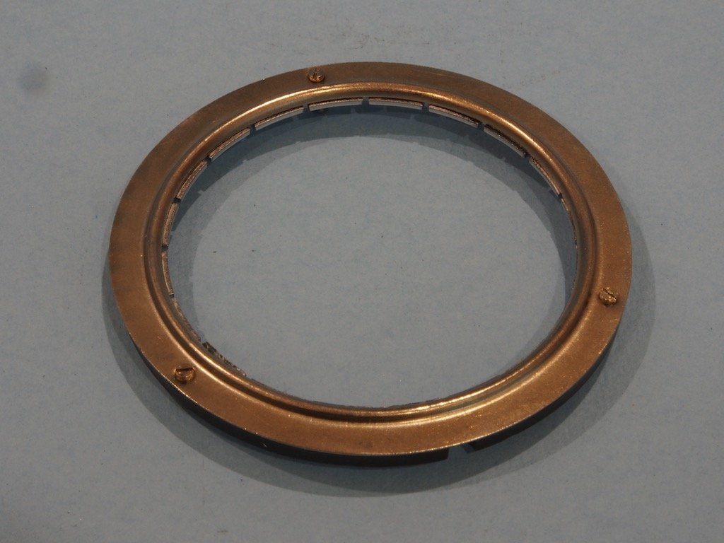
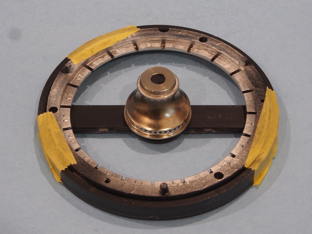
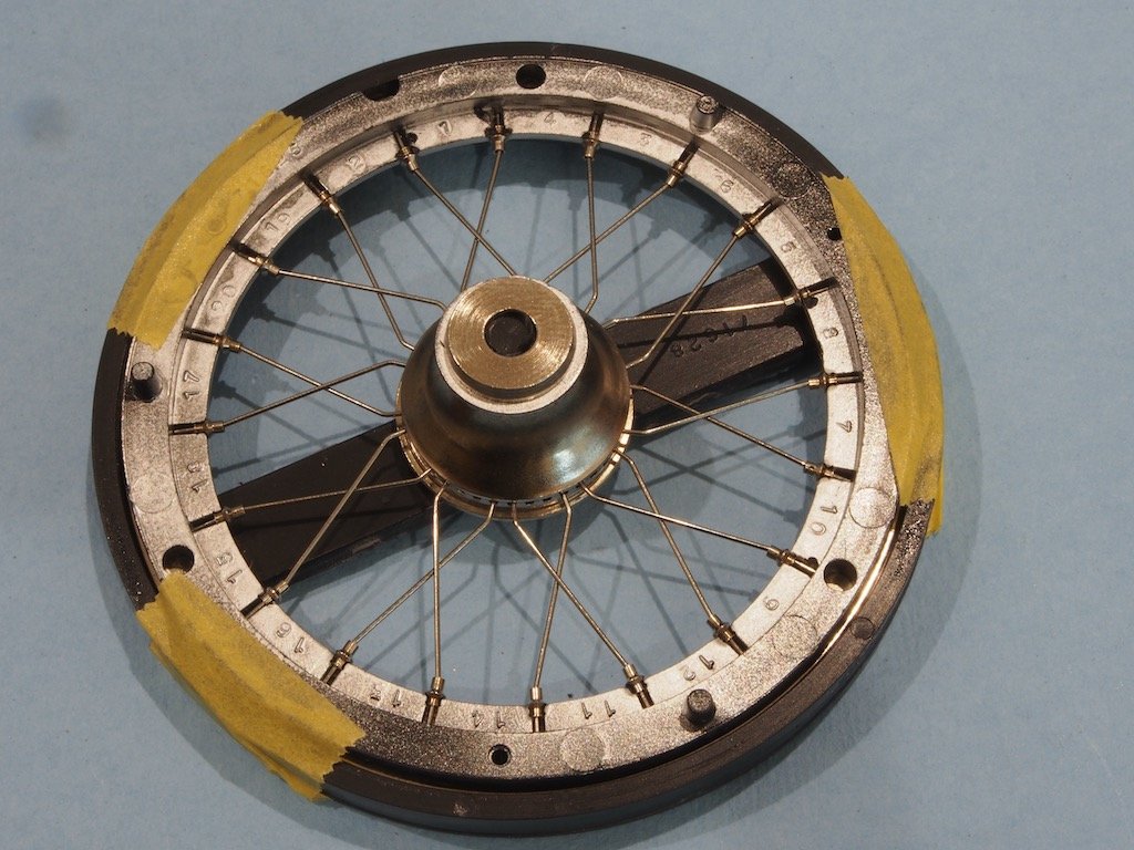
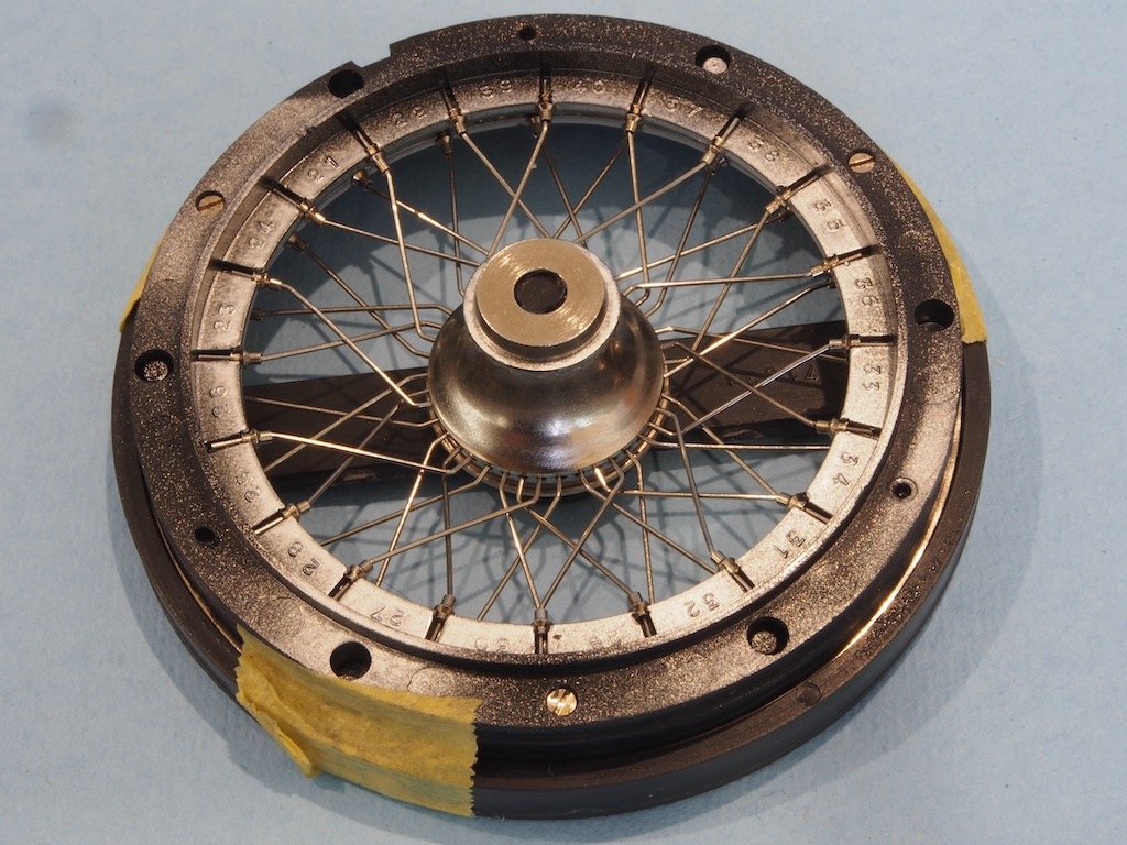
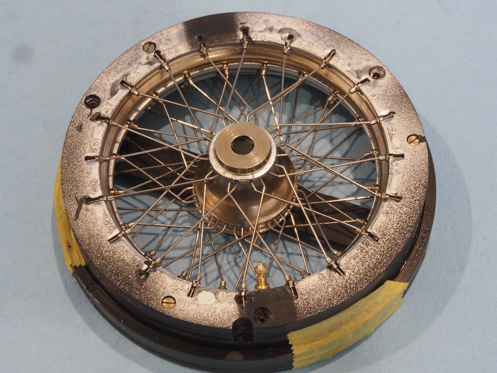
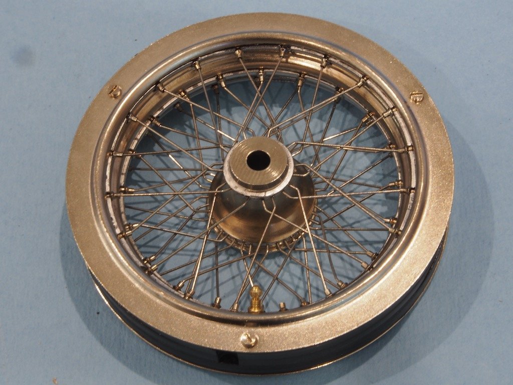
Thanks again for all the nice comments and the likes, and thanks Egilman for bringing the thread back on track after some interesting side discussion. On with the show! The Wire Wheels The wire wheels are an interesting challenge in themselves! The wheel hubs are made up of 4 metal and two plastic parts as shown in the photo below. The two plastic parts have notches cut into them to accept the spokes, and these need to be checked to ensure they are not blocked by flash. The outer rim of the plastic parts also needs to be painted chrome to match the metal parts. Once assembled they look like this: The wheel rims are comprised of three plastic and four metal rings. The plastic rings accept the spokes and the spoke hubs. Again, the plastic parts need careful checking for flash and the inner rim surfaces painted chrome: The kit provides an assembly jig for the wheels. In fact, it provides six of these, however few of them are particularly true. Paul Koo’s advice is to find the one that is closest to true and use it for building all six wheels. So that is what I did. Assembly commences by attaching one of the two outer metal rings to the inside of the inner plastic ring. Although it is held in place with three screws, Paul advises that these will later interfere with the fit of the tyre, so his advice is to use glue as well as the screws, and then to remove the screws once the wheel is fully built. So that’s what I did. The rim is then inverted, placed in the jig and held in place with a few pieces of masking tape. The wheel hub is also inserted onto the jig at this point. This is where life starts to get interesting. There are three layers of spokes to make up each wheel. Each of the three layers uses spokes of a different size and shape, so it’s important not to mix these up. Now, if you were to follow the Pocher instructions, they would have you build the wheels with an asymmetrical spoke pattern. This is problematic in that for this to work, within each layer of spokes you would really need two different sizes of spoke – one for clockwise pointing spokes and one for counter-clockwise pointing spokes. As Pocher only provides one size of spoke for each layer, this would mean trimming and adjusting half of all the spokes. Paul provides a much simpler solution that produces a symmetrical spoke pattern and therefore only needs one type of spoke for each layer. Not only does the symmetrical pattern look better (in my view), it is also stronger and more stable. Each spoke is inserted into the wheel hub and then has a spoke hub slipped over the outer end. The spoke hub has a small flange on it and this is pressed into the outer plastic ring in the appropriate place. The flanges are meant to press-fit into place, using a small screwdriver to push them in. Good luck with that! Paul advises using the “melting method” if the flanges are difficult to push into place. This is about the time I blessed Paul (again) for advising on the melting method earlier in the build, so I’d had some practice with it before attempting this task. Essentially, the spoke hubs were pressed partially into place and then they were touched with a hot soldering iron tip until they melted their way into the plastic. It sounds like a brutal way to do this, but is remarkably finessed. Once you’ve done a few, you get a real feel for it and the whole process goes quite quickly. Here is the completed first layer of spokes: The first of two inner metal rings is then inserted, followed by the middle plastic ring. There are three locating lugs to position the middle plastic ring before it is screwed in place. However, because we are departing from the Pocher build method, this ring needs to be rotated 120 degrees (ie one locating lug) clockwise. Insertion of the spokes continues in a similar manner to the first layer, with the inner ends being inserted into the remaining spaces on the inner hub ring. Here is the completed second layer. The second inner metal ring, which includes the tyre valve, is now inserted followed by the third and final plastic ring. With this layer, the spokes are inserted into the outer/upper hub ring. Finally, the outer metal ring is attached, again using glue as well as the screws. Continued next post...
- 224 replies
-
- 12
-
-
Beautiful job OC - she looks outstanding!
-
This is a nice little vessel and an interesting kit - I have one in my stash....somewhere.... I’ll pull up a chair and follow along for this build.
-
Looking very smart Sjors!
-
I think we’ve all “been there, done that!” OC. We’ll just have to look forward to seeing updated pics next time.
