


gjdale
-
Posts
4,814 -
Joined
-
Last visited
Content Type
Profiles
Forums
Gallery
Events
Posts posted by gjdale
-
-
Great job on the shingles and the chimney Jeff. Adding the brass wire pin and support block for the chimney was a wise move.
- Canute, Old Collingwood, Jack12477 and 4 others
-
 7
7
-
Congratulations Glen, a real masterpiece in miniature. As others have already said, whimsical, creative, amusing, and highly skilled execution. You’ve set a high bar my friend - I’m looking forward to your next creation.
- Keith Black, Glen McGuire, Knocklouder and 1 other
-
3
-
 1
1
-
Looks great Jeff. I like your solution to the deteriorating decals - I'll need to keep that in mind when I get around to this kit myself.
-
Thanks Bob. 🙂 Perhaps I should use the table saw to prepare the vegetables in future - at least it is a Sawstop saw, so no fingers will be harmed in the process! 🤣
-
Thanks Glen - you made my day with that one! 🤣
I'll work on a new story.....
I reckon Keith will be able to help out with the narrative - I'm sure it will feature killer penguins!!! 😉
- Edwardkenway, Old Collingwood, mtaylor and 7 others
-
2
-
 8
8
-
-
A quick update to say there won’t be an update for a couple of weeks at least. A mishap with a kitchen knife last night resulted in a trip to emergency and a thumb now wrapped in bandages for a week or so. Not too serious - sliced a good part of the pad of my left thumb away - but no modelling (or anything else that requires thumbs for that matter) for at least a week.
I’ll be back once work is underway again.
- Keith Black, FriedClams, Canute and 8 others
-
 11
11
-
8 hours ago, Chuck said:
But lucky me it fit just perfectly.
I don’t think luck had much to do with it Chuck! More like a testament to your design (and build) skills.
-
4 hours ago, Glen McGuire said:
I was trying to get a match for this color of ocean water below
I’d say you nailed it Glen!
- Keith Black, hollowneck, Glen McGuire and 2 others
-
4
-
1
-
3 hours ago, Glen McGuire said:
I know, it looks like he's in a kiddie wading pool!
Your next project then? 🤣
- FriedClams, Glen McGuire, mtaylor and 1 other
-
2
-
2
-
Thank you Glen, Bob and OC.
7 hours ago, Glen McGuire said:What are the dimensions of your base?
The base is 18” x 17 1/2 “ x 3/4” MDF, with 30mm thick styrofoam (house insulation) on top.
-
57 minutes ago, wefalck said:
Where are you going to put the ship on the stocks?
There is some scenic sculpting/grading to be done Wefalck, and then the ship will be positioned fairly close to where it is in the photos above.
- Keith Black, Egilman, FriedClams and 6 others
-
8
-
1
-
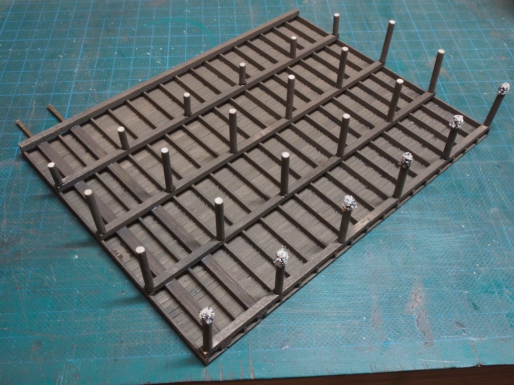
The Dock Pilings
Completion of the Main Dock is fairly straight forward. Having previously determined the correct length of pilings required, it was simply a matter of graining and staining the 1/8” diameter dowels and cutting them to length. The position of the pilings is indicated on the provided template and the instructions suggest adding three rows of full height pilings and one row of half height pilings – the latter being to accommodate the addition of scenery base.
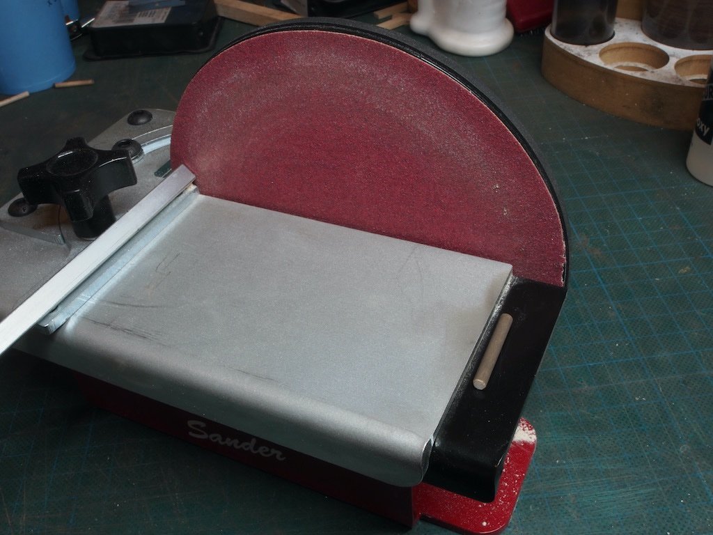
I will digress for one moment to show off my newest toy. It is a hand operated disc sander (by Ultimation) and is brilliant for fine tuning and especially for squaring ends. Although I already own a very good, powered disc sander (Byrnes), the hand operated version offers excellent fine control. I stumbled across this reading through the Sierra West forum.
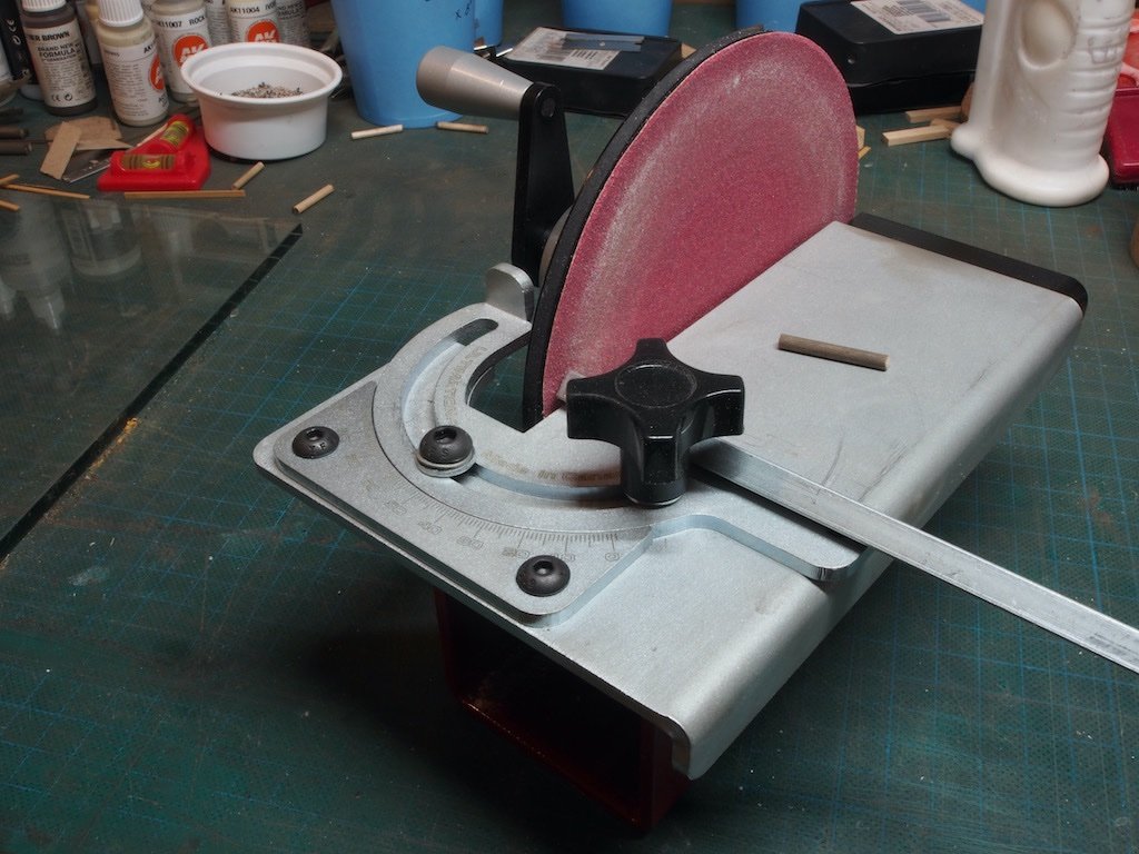
A neat feature is that there is a ledge at the end of the table that provides a perfect 90-degrees – very useful for squaring up ends.
Once all the pilings had been cut and the ends de-fuzzed and squared off, I drilled a 0.6mm hole in the end of each and inserted a piece of 0.5mm brass rod to act as a locating pin and to assist holding the pilings in place while the glue dried. The pilings were all attached using 5-min epoxy. The instructions also direct us to add barnacles to the first row of pilings at this stage – a task that would be better left until after the addition of the bracing.
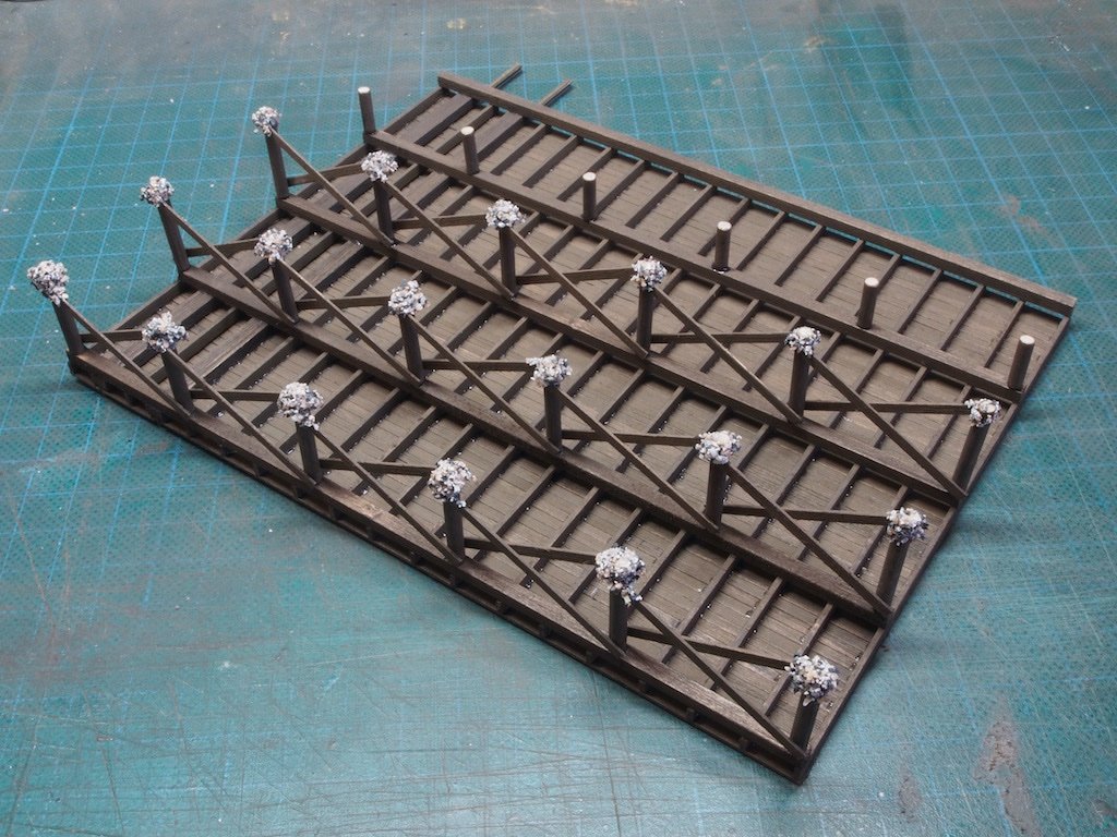
Bracing strips are then cut to length (using the template) from 0.020” x 3/32” strip that has been grained and stained. The instructions then again direct us to add barnacles to the first row. This is the right time to do this, as having already done it prior to adding the bracing, I then had to scrape most of it off to allow the bracing to be placed properly. I also decided to add the barnacles to all of the first three rows.
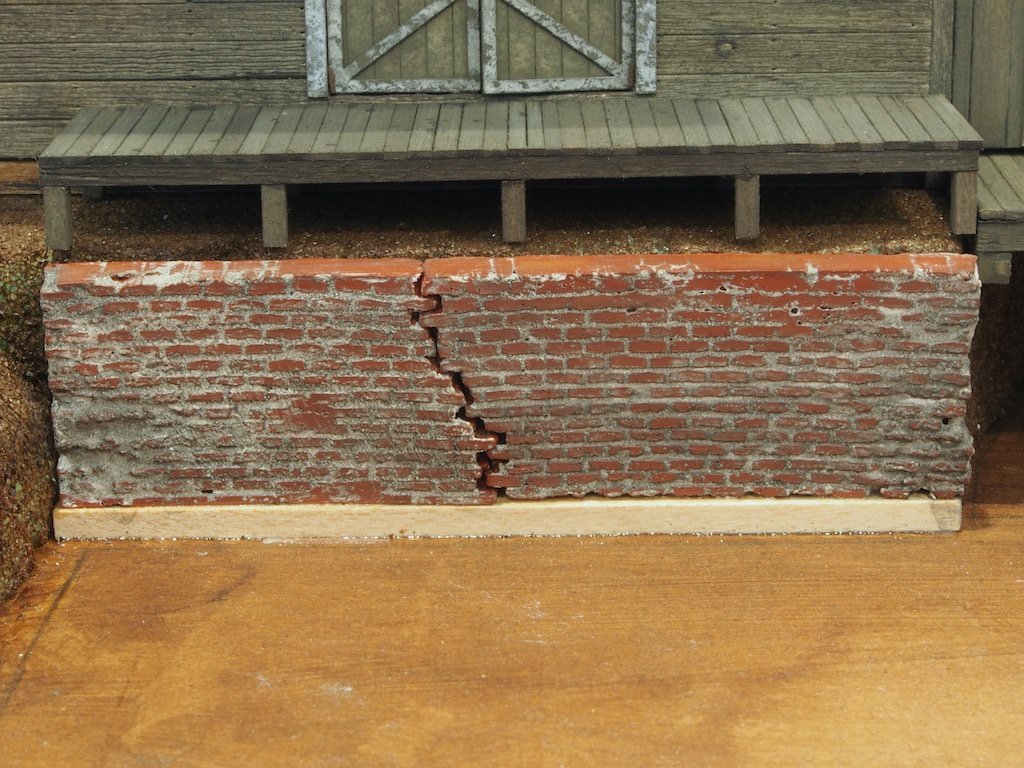
That completes the main dock. I then decided to re-visit my brick wall. One of the Sierra West gurus had kindly suggested that it might be a good idea to tone down the brightness of the mortar by applying a light wash of alcohol and ink. I did this and am quite pleased with the result.
The next step will be adding the scenery base before “planting” the ship and adding the scaffolding around the ship. I must confess to being somewhat apprehensive about this stage, only because I have never done anything like this before. What could possibly go wrong?
In the meantime, here are a few “spin” shots of all the completed work to date. The diorama has been cleverly designed to present an interesting view from all sides.
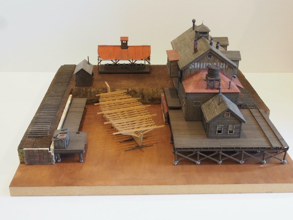
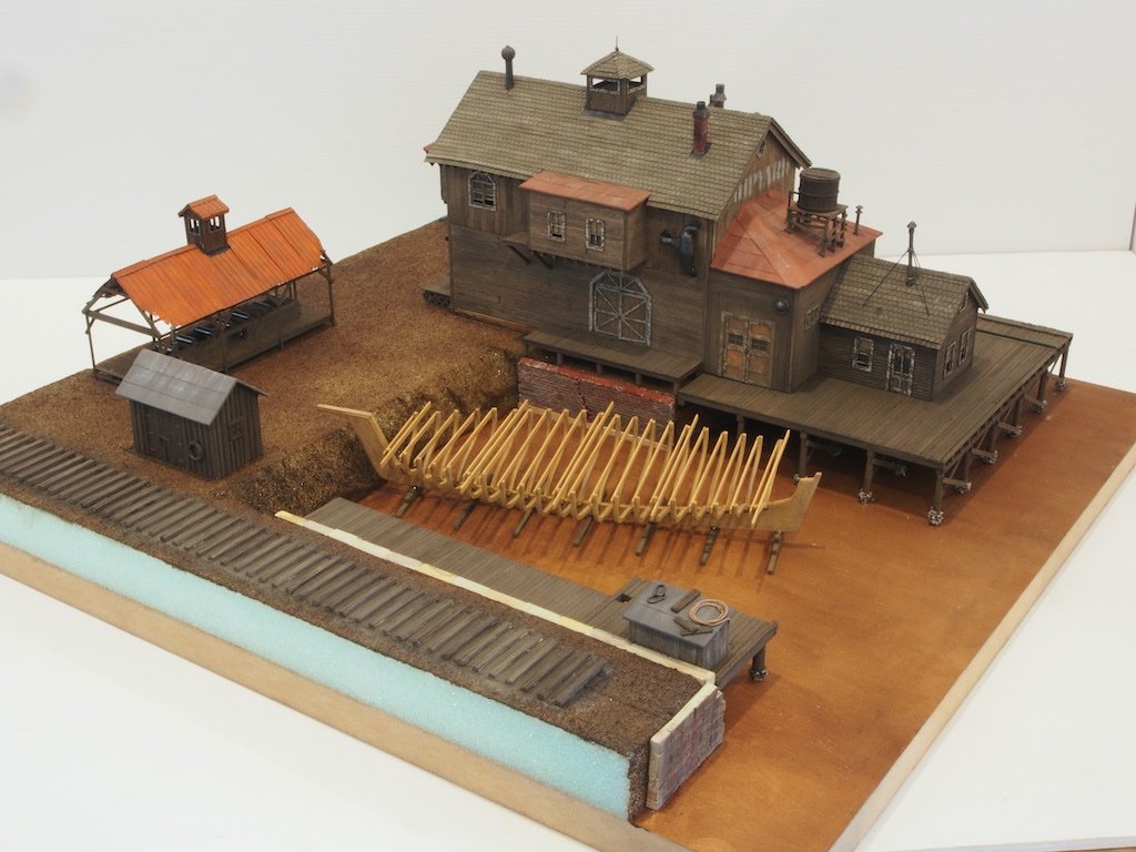
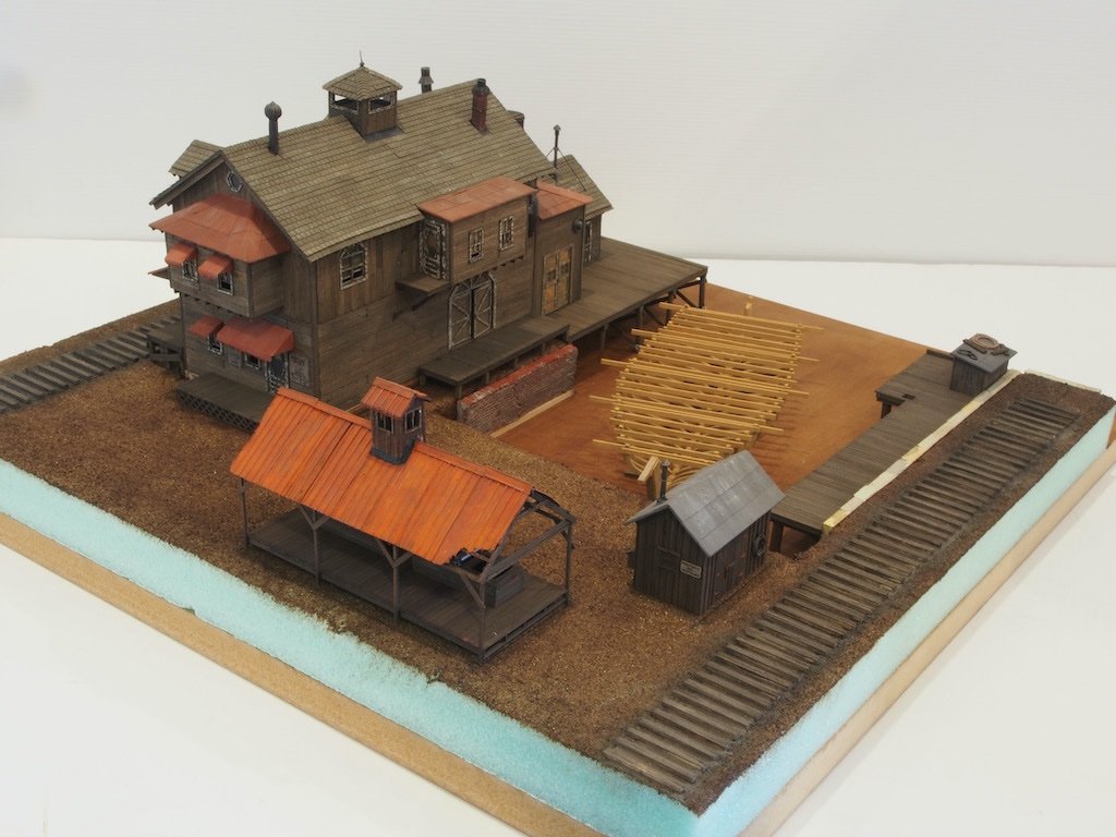
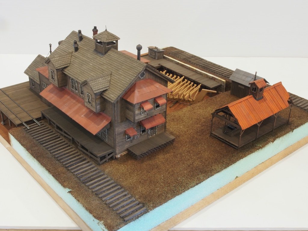
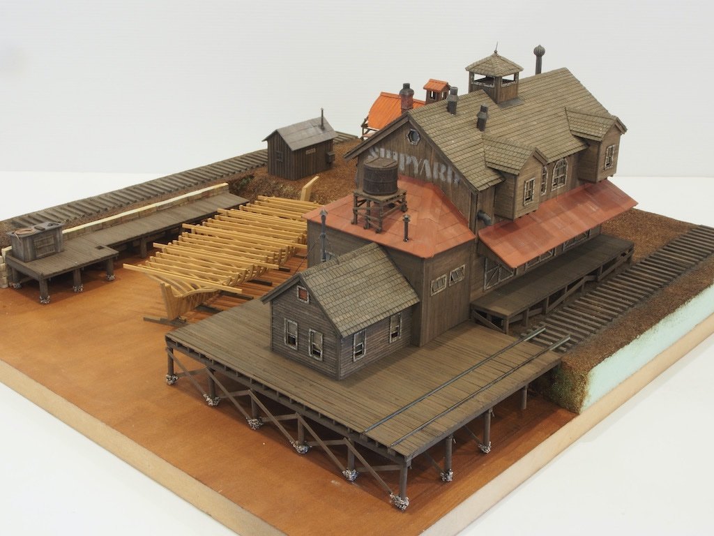
I’ll be back once the scenery base is underway…
-
6 hours ago, Glen McGuire said:
Love the hair clip clamps! Such a great idea.
I can’t take credit for that idea Glen. I picked that one up from the late, great Danny Vadas, right here at MSW - one of the reasons this is such a great site and such a great resource.
-
You’re doing a good job so far Etubino. Despite its many shortcomings, this kit does build up into a very nice model if you are patient and persevere. Be careful with the instructions. If memory serves me correctly, they will “paint you into a corner” regarding placement of some of the guns by advising you to insert completed guns/carrriages through the gun ports to the quarterdeck after the Poop deck has been fitted above. The guns/carriages won’t actually fit through the gun ports, so you will need an alternative solution.
-
Great start Jeff. As it happens, I also have the Foss’s Landing kit in my stash but decided on doing the Shipyard first. Perhaps we can learn from each other as we go.
- Egilman, Jack12477, king derelict and 3 others
-
6
-
Just fabulous Glen. Looking forward to seeing the final rendition with the water effects in place.
- Knocklouder, Glen McGuire, Keith Black and 1 other
-
3
-
1
-
It's been a little while since the last update. Although progress has been slow (even by my usual glacial standards), there has been progress nevertheless!
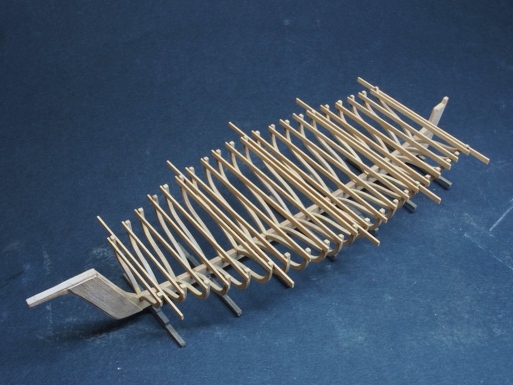
The Ship Under Construction
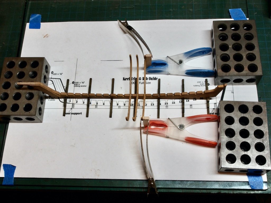
With the keel and ribs re-stained to a more appropriate colour, I was able to return to building up the ship. To start, I copied an idea from another build log and taped my template to my glass plate, and then covered that with a sheet of baking paper. I then drew some reference lines for the placement of the keel supports and applied three thin strips of double-sided tape before positioning the keel supports in place.
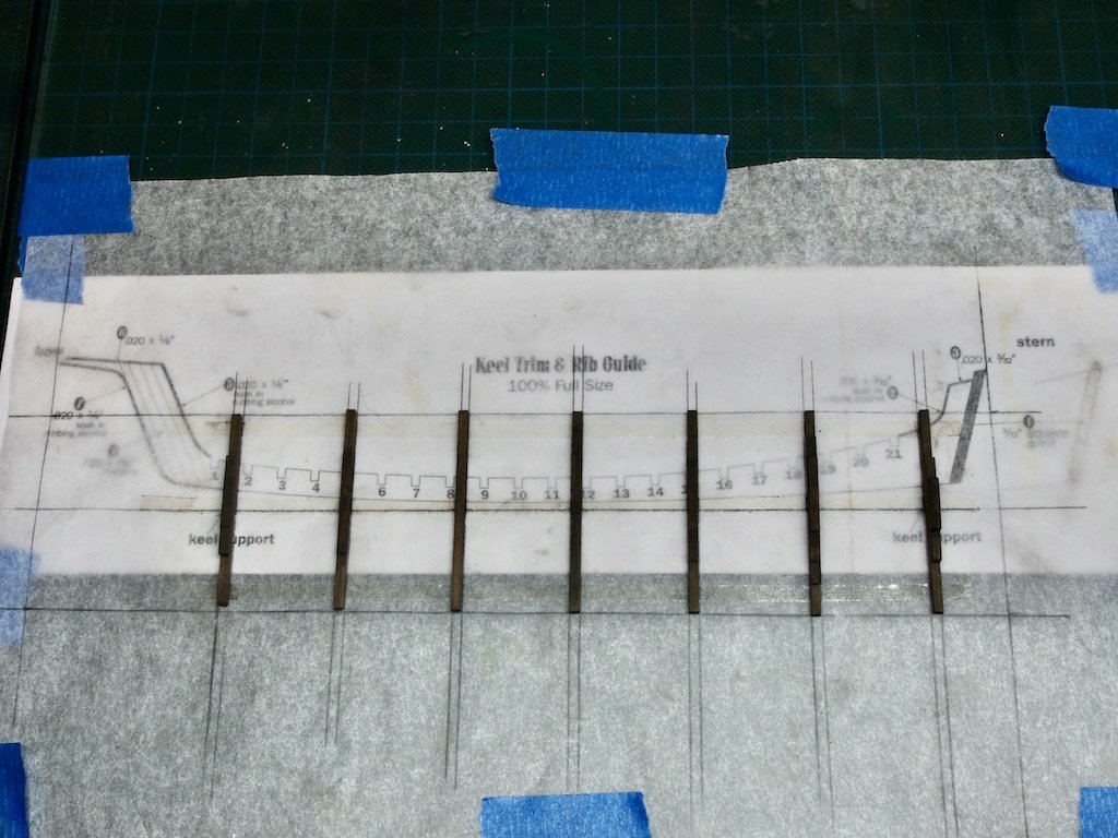
With the keel supports held securely in place, I then added a drop of epoxy to the centre of each and placed the keel. In the picture below, you can see my method for ensuring that everything remained square while the epoxy set.
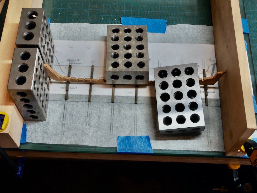
Once the keel was securely attached to the keel supports, I was able to start adding the frames/ribs. Again, pinching an idea from the same other build log, I cut a pair of support strips to ensure the ends of the frames were at the same height. These are simply held with a clothes peg to provide a stable base. The tops of the frames are clamped to the top of the support strip while the glue dries. The “clamps” in this case were simply hairdressers sectioning clips – I found these had just the right amount of clamping pressure for the job.
It was tediously slow work to attach all the frames as I needed to wait for the glue to set up on each frame before moving on to the next. However, eventually they were all in place.
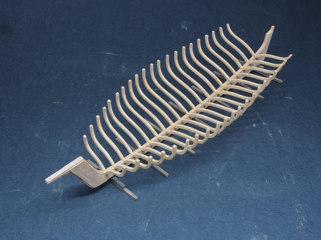
Support braces are then added to the fore side of the top of each frame. We begin by attaching a brace to the second frame from each end, again using the hair clips as clamps, and then a scrap piece of squared wood is used as a guide to ensure the levels are even.
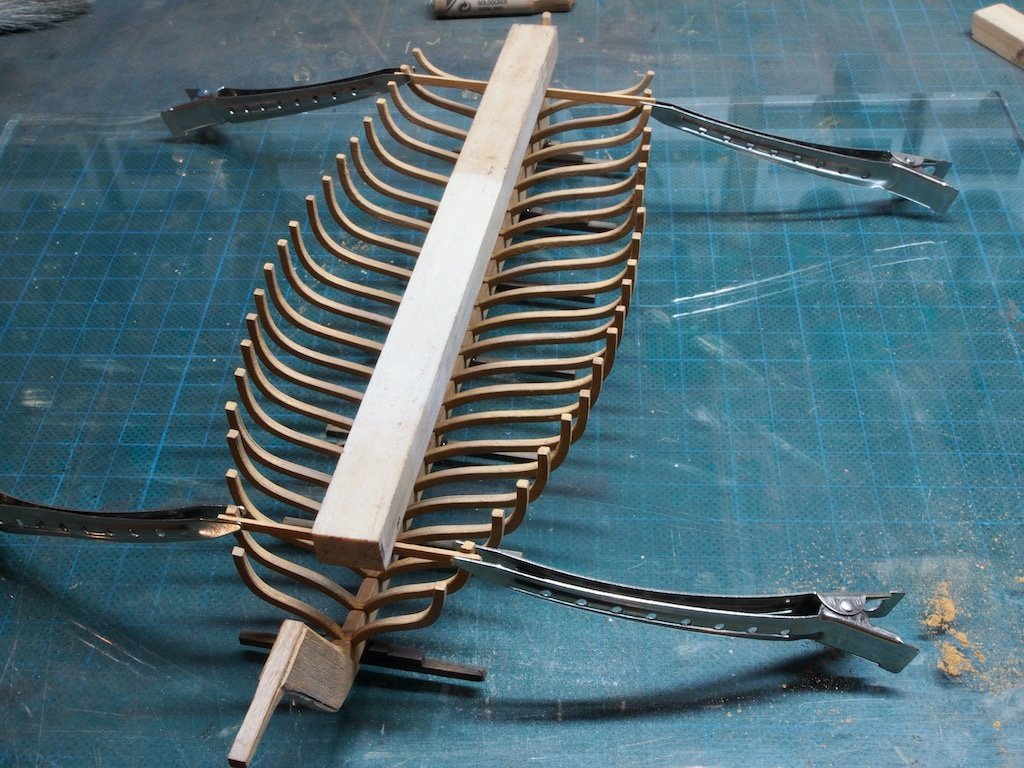
The remaining braces were then added two at a time, using the longitudinal guide to ensure that they are all at the same level.
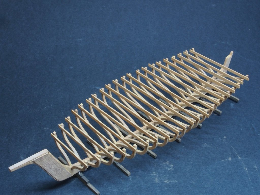
Once these braces were all in place, five more braces are added to the aft side of frames 1, 6, 11, 16 and 21. These braces will be part of the scaffolding support at a later stage in the build (once the ship has been placed in the diorama base).
We leave the ship for now and return to completing the dock pilings….
-
12 hours ago, Rustyj said:
Now while pressing it in place someone not to be named was not aware of where they were placing one of their fingers and while applying pressure said finger pressure snapped off two deadeyes.
While I wouldn’t wish this on anyone, it is at least comforting to know that even someone of your skills can still manage to do this Rusty! Thank you for being human after all - it gives the rest of us hope.
- James G, Edwardkenway, Ryland Craze and 1 other
-
2
-
1
-
1
-
As others have said Rick, a fine model of which you can be justifiably proud. Congratulations and well done! I’m sure you will enjoy similar success with your Cheerful build.
- Ryland Craze and Freebird
-
2
-
-
Always a joy to watch you work your magic BE. I’m taking a front row seat for this one.
- Blue Ensign, chris watton, mtaylor and 2 others
-
5
-
Thanks very much Glen, Gary and Bob - the boo-boo was one of those Homer Simpson moments (Doh!). Just a really stupid, avoidable mistake. You may not notice it, but it will forever be the first thing I notice when I look at it! That’s just the way we are as modellers.
1 hour ago, BobG said:Is DSPIAE an acronym or a brand name? Also, what brand and model is your small drill press?
DSPIAE is the brand name Bob - I don’t know if it is also an acronym. My drill press is a Proxxon TBM 220. I’ve had this for quite some time now and have found it very useful for general purpose work and it lives on my modelling desk always at hand. I also have the fall back of the Sherline Mill with sensitive drilling attachment for even more precise work when needed. 😊 I think I am well placed in the competition for “he who dies with the most tools wins”………….😉 I just hope that when I do fall off the perch, my wife doesn’t sell my tools for what I told her I paid for them………
-
Thank you very much OC, and to all of the likes.
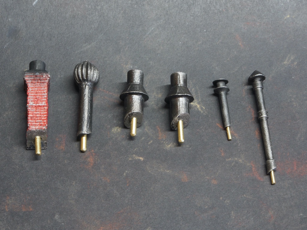
With the roofs now complete, I was able to turn my mind to the roof hardware installation. My concern here was that as these parts were nearly all made from white metal (except the chimney, which is resin) and they all had angled bases to sit against the roof, they would be difficult to hold in place while the glue dried. I decided to add a small spigot to the inboard end of each piece, to be inserted into a corresponding hole to be drilled into the roof. My hope was that the spigot would provide the necessary stability while the epoxy set.
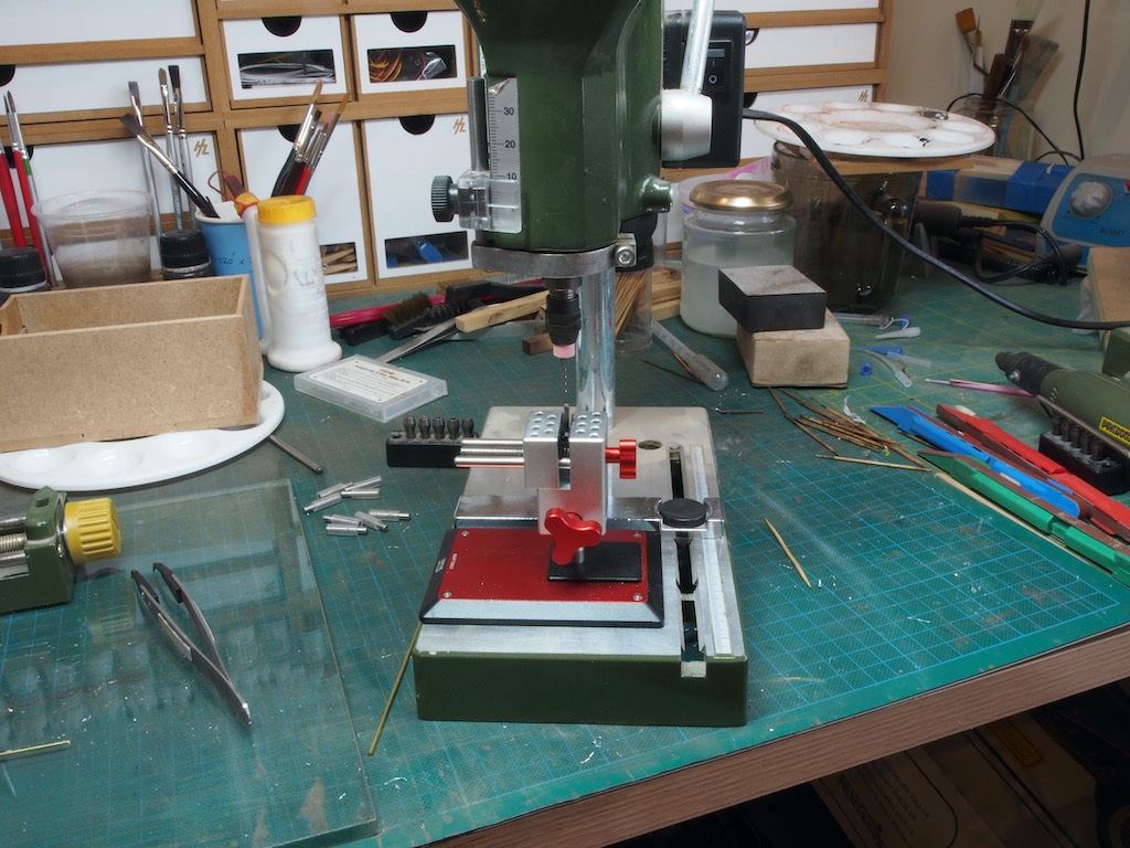
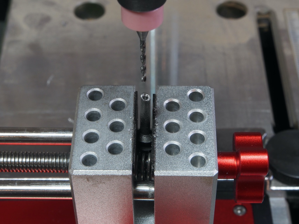
For the four larger diameter pieces, a 1/16” (1.6mm) brass rod could be used for the spigot, however for the two smaller diameter pieces, only a 1mm diameter piece could be used. Drilling these holes into the angled bases without the drill bit deflecting or breaking was the key challenge here. Once again, my little DSPIAE vice proved its worth, holding the piece securely under the drill press.
Here is one of those smaller pieces being drilled with a 1.1mm bit. (This is the tidy side of my work space!)
And a little closer shot.
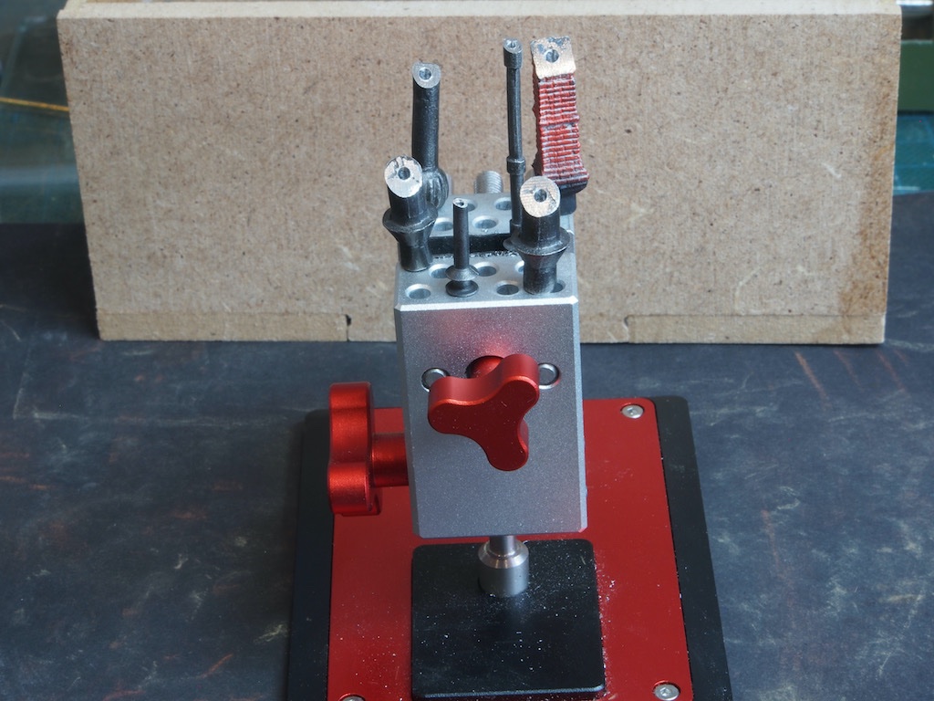
And here are all the pieces drilled and ready to receive their spigots.
A short section of brass rod was then epoxied into each of the pieces and locating holes carefully drilled into the roof using a pin vice.
The individual pieces were then epoxied in place and the spigots did their job of holding things securely while the glue cured.
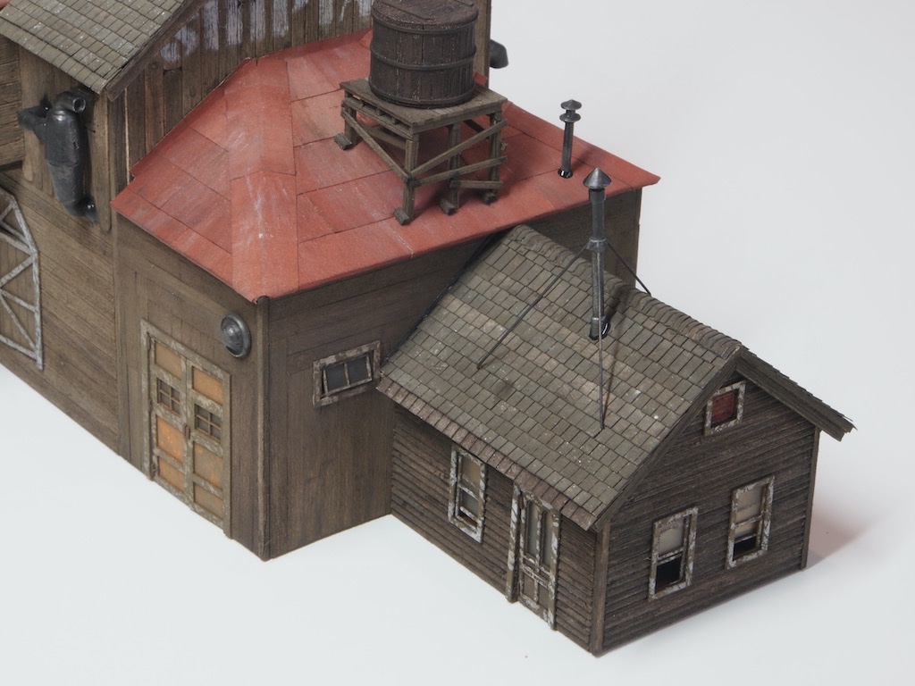
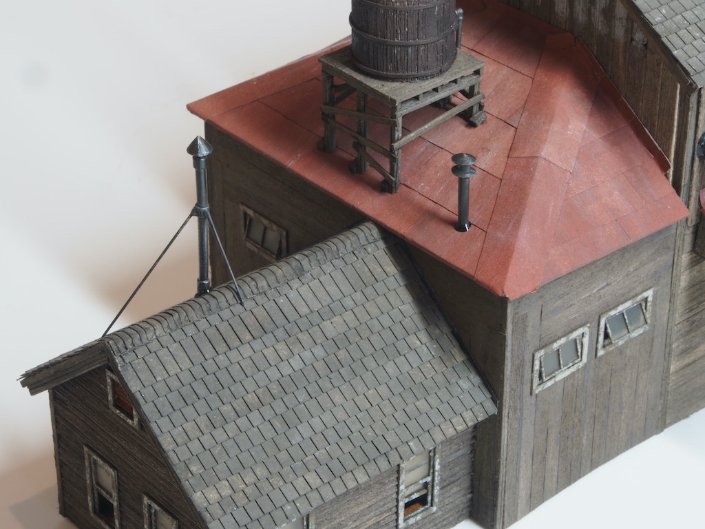
Once the glue had cured, the stack on the Yard Master’s Office had three supporting wires attached. These were made from 0.5mm diameter brass rod, cut to length, blackened, and then epoxied into place. To assist in positioning these, a small “elbow” was bent into the bottom end of each and inserted into a corresponding locating hole drilled into the roof.
Here are a few overall shots of the roof hardware in place.
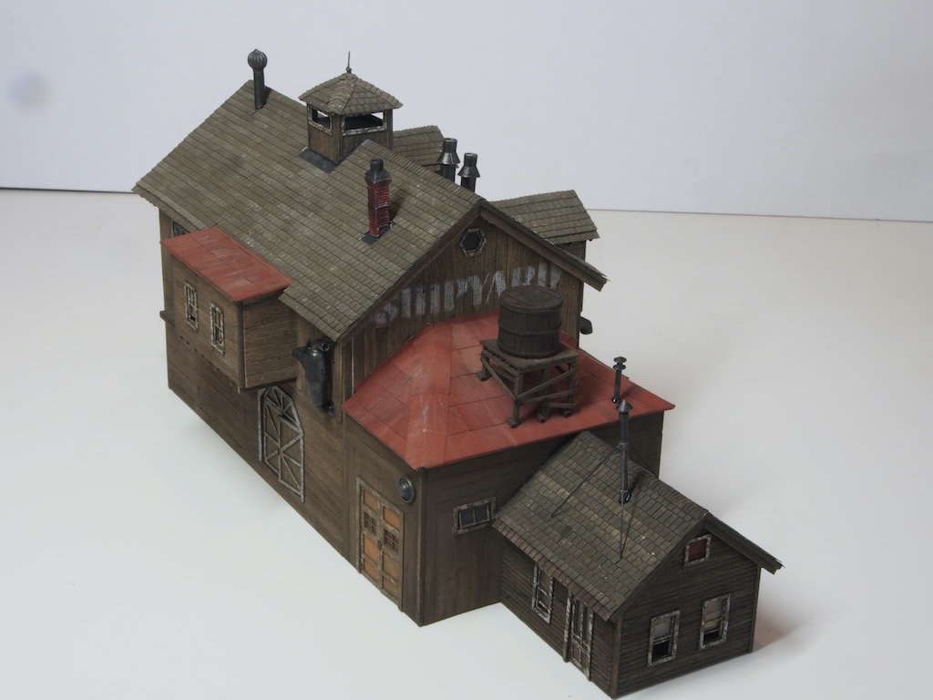
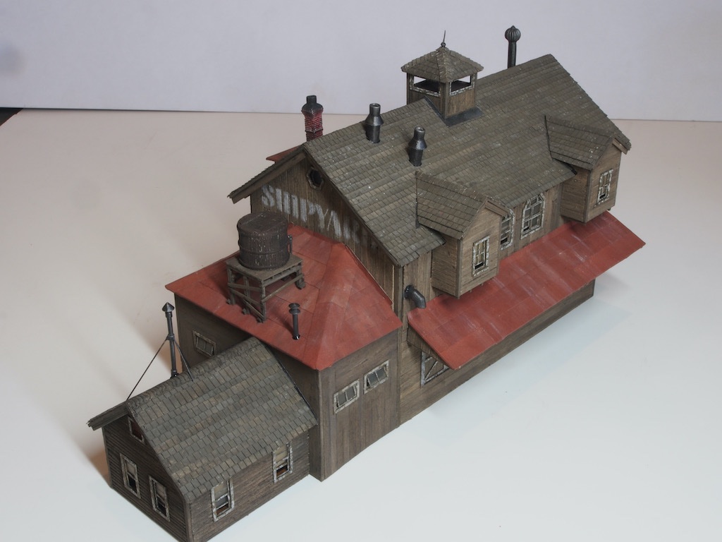
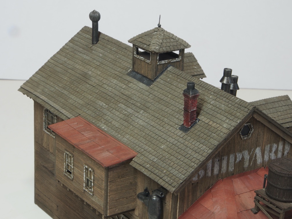
At some point I managed to knock off the top of the lightning rod on the top of the cupola, but managed to glue it back in place with some CA gel – still looks a bit wonky in these pics – may have to try and straighten later.
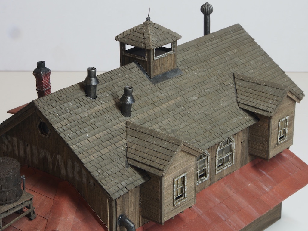
And here is the Yard Master’s Office Roof:
In the above photos, you can see the boo-boo I made when shingling the Yard Master’s Office roof. I only spotted this when I was installing the roof hardware. I knew that I had to use a thinner shingle strip for the final row, but I forgot that I should have still used a normal width row first, and then placed the thinner row on top. The result is an elongated row of shingles (second row below the capping). I briefly considered whether this might be salvageable, but in the end decided that it was too high a risk of doing extensive damage. I will just have to live with this one.
Looking at the close-up photos, it looks like I need to go back and dull down some of the "pitch" at the base of some of the hardware items too.
With the roofs finally complete, I can now return to the ship under construction.

The Shipyard at Foss' Landing (Diorama) by gjdale (Grant) - FINISHED - SierraWest - Scale 1:87 (HO)
in Non-ship/categorised builds
Posted
Having had some enforced time off due to the "attack of the killer carrots", it's time to resume normal programming.
The Scenery Base
Having read through the instructions several times, including reading ahead to the next section, I decided to do things a little out of sequence and make up some of the scaffolding that would be needed shortly. I wanted to have this on hand and ready to go when it was needed, rather than making it up while watching the clock on setting times for the scenery base.
The scaffolding items are relatively simple, and all are made according to provided templates in the plans. These consist of the bow and stern scaffolding assemblies, the scaffolding walkways and two ramp pieces. Here they are ready to go and put aside until needed.
Not shown here, the keel bracing was also added at this time rather than waiting until the ship was placed in the scenery. These are simply bracing pieces that run from the outer ends of the keel supports to the keel itself. Sorry – no photo of this bit. As it turned out, I was very glad that I installed these at this point.
The next step was to mix up some Sculptamold to contour the shoreline and create the pit for the ship. I was very apprehensive about this as I had never done anything like this before and it is also a “point of no return”. It actually took me three attempts at mixing the Sculptamold before I had a consistency that I was happy with. A cardboard template of the ships keel is provided to assist in shaping the pit area. A little AK 11008 paint (in place of the called for Polly Earth) is added to the water before mixing with the Sculptamold. I also added a few small stones to represent rocks in the area under the dock.
In the picture above you can see the indentation made for the rear pylons of the dock. The instructions say to spread a base layer of dirt over the Sculptamold before pressing the ship down to sink the keel supports just a bit into the Sculptamold. I found that the surface of the Sculptamold had already hardened to a point that made this impossible, so I mixed up a fresh batch, spread it over the area where the ship was to go, and then placed the ship into it. I subsequently added some more dirt over the top. The barge derrick dock was also placed at this time. I was able to create some holes in the Sculptamold by pushing a 3/16” diameter brass rod into the mix. This allowed me to place the supporting pylons at the right depth for the height of the dock surface. A little epoxy was added to the bottoms of the pylons to secure them in place.
Once a layer of dirt was added, it was then lightly wet down with “Wet Water” (water with a few drops of dish detergent) sprayed from a plant sprayer bottle. A mixture of 50/50 white glue and water, with a couple of drops of dish detergent, is then applied over the entire surface using an eyedropper/syringe.
At this point, I also decided to change the colour of the bottom of the water area and added that by applying some artists acrylics – a mix of Turquoise, Phthalo Green, and Aquamarine – trying to have the lighter green colour towards the shore, and a deeper blue further out to represent the deeper water.
In the above picture, you can see on the left-hand side where an errant brush stroke hit the sea wall. I was able to remove this later with the gentle application of an alcohol/ink wash.
Completing the Ship
Once the base had dried, I decided that I didn’t like the plain dark brown of the floor of the pit, so I mixed up some sand and two different light-coloured HO scale ballasts, and sprinkled that over the dirt, again applying a white glue/water mix to seal it in place.
The main scaffolding supports were then added. Once again, I found that by using an awl to make an initial indentation, I was able to push the supports down into the Sculptamold. These were each glued to the scaffolding rib braces previously installed on the ship. Additional keel supports were also added at both bow and stern.
The scaffolding walkways could then be glued in place.
The two-part ramp was then added to the port side. As suggested by the instructions, a slight bow was imparted into the lower section, adding to the appearance of age.
Finally, some bracing pieces were added between neighbouring scaffold brace supports. Two ladders were made up and placed, and a scrap wood chute was made up and placed towards the bow end. Then some small pieces of scrap wood were added to the chute, and more scraps were scattered around the pit. All of these scraps were given the white glue/water mix treatment to secure them in place.
It's a bit hard to see in the photographs, but the white glue/water mix has left a bit of a sheen on the scrap wood pieces. I may need to go back and carefully apply some dull cote to knock that back. In the meantime, that completes the work on the ship and the next step will be construction of the barge derrick.