


gjdale
-
Posts
4,819 -
Joined
-
Last visited
Content Type
Profiles
Forums
Gallery
Events
Posts posted by gjdale
-
-
So nice to see you back on the forum Mark - I hope we will be seeing more of you soon.
- kruginmi, Keith Black and egkb
-
 3
3
-
Nice recovery Glen!
- mtaylor and Keith Black
-
2
-
Thank you so much EG, Glen, Mark and OC - you are too kind. Thanks also to all of the likes as well.
Wall Construction – Wall Details (Right Wall)
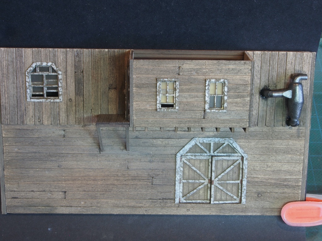
Details for the Right Wall commence with the large awning for the Loading Dock. A laser cut card piece forms the substrate, which is painted on the underside and has tarpaper applied to the topside. The preparation for this is the same as previously described. There are four support struts, again in laser cut card, which are also painted and the two outer supports also have siding and trim applied. I got a bit carried away with the process and forgot to take many in-progress pictures. Here is the back of the almost completed awning.
And a shot to show the siding and trim applied to the end pieces.
The top of the awning then has the streaking effect applied as previously described.
The awning is then attached to the wall using the cleverly designed location markers. An elbow vent is also provided as a metal casting. This was prepared and blackened as previously described and glued in place with some epoxy coloured with a little black paint. The paint/glue is dulled with a little grey chalk and some dull cote once the glue is dry to take off some of the shine. Here is the completed (for now) wall.
The next step will be to join the walls together and add the roof, before adding the two remaining dormers that were prepared earlier.
- popeye2sea, Keith Black, Egilman and 16 others
-
18
-
 1
1
-
Off to a great start BE. I always enjoy following your build logs - this will be no exception, I’m sure.
- Knocklouder, hollowneck, mtaylor and 1 other
-
4
-
5 minutes ago, Glen McGuire said:
So I’m in the process of bending my deck layers with my heavy pieces of railroad track
Am I the only one here who doesn’t just happen to have heavy pieces of railroad track lying around waiting to be used to bend wood? 🤣🤣🤣
Love your plan Glen. Yep, revisions between paper and product are all too frequent - at least in my workshop!
- Keith Black, Glen McGuire and mtaylor
-
2
-
 1
1
-
Thanks very much Ken and Gary, and also to all of the likes. Gary - high praise indeed. If I end up with something half as good as your dioramas, I'll be well pleased!
Wall Construction – Wall Details (Left Wall)
Details for the Left Wall commence with attaching the Dormer to the wall and adding the floor joists under the Dormer. This is done in the same way as for the Rear Wall just completed.
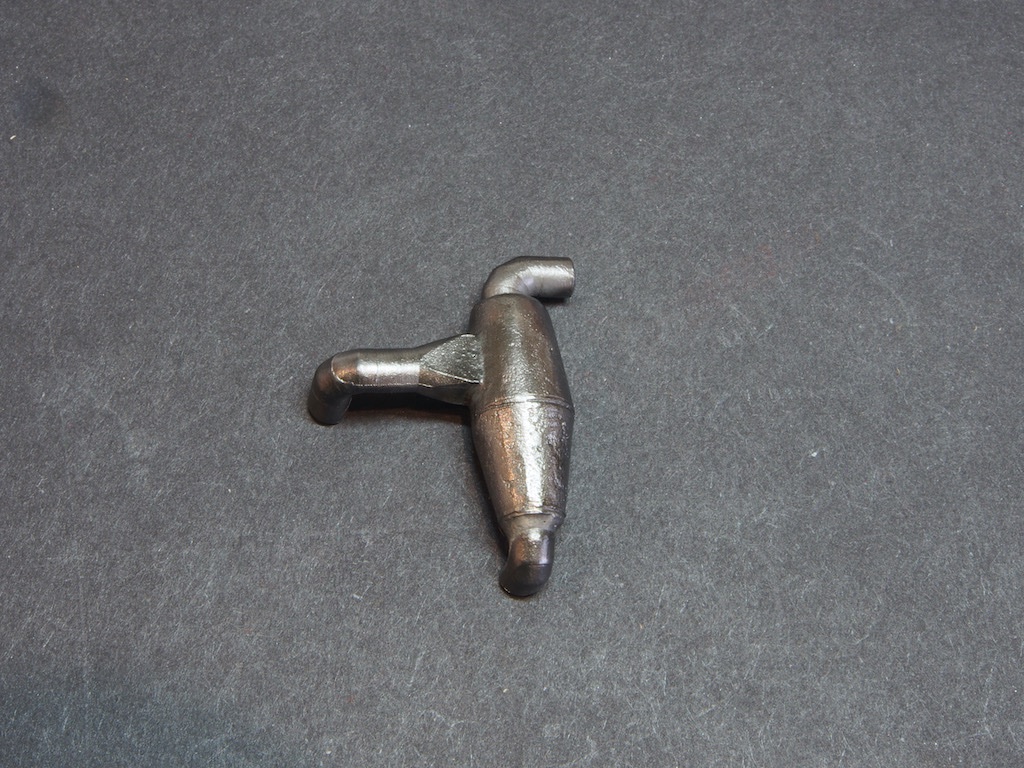
The next item to add is the Sawdust Collector. This is a cast metal item that was cleaned up with a combination of #11 blade, file and brass brush mounted in my Proxxon rotary tool.
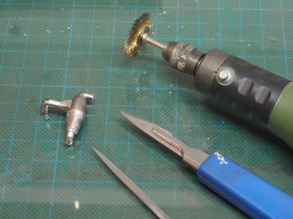
Here’s what it looks like after clean-up.
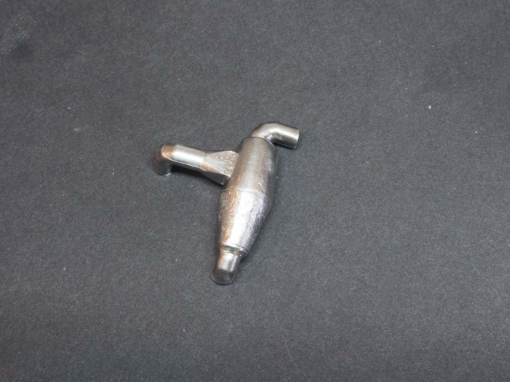
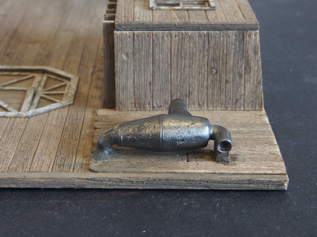
It was then blackened using Jax Pewter Black and buffed with a felt wheel in the rotary tool.
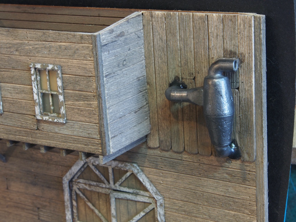
It was mounted to the wall with epoxy darkened with a little black paint to represent tar and pitch, allowing a small amount to ooze out around the joint. Once dry, a wooden brace was added between the Sawdust Collector and the wall.
Next, the landing is constructed using the provided template.
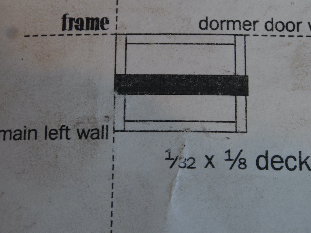
Rather than cutting directly onto the template, I used scraps of wood to set the length of a stop on my Chopper in order to ensure pieces were identical in length and cut square.
Once cut, I placed some double-sided tape over the template and glued the parts together over the template, using a straight edge to ensure that it was square. Once dry, some nail holes were added and the piece removed from the template.
The landing is then attached to the main wall and the Dormer door wall. Two braces are cut to length and angle using the template as a guide, and attached to the landing and the wall.
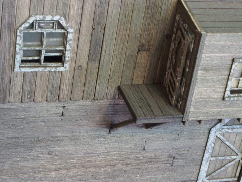
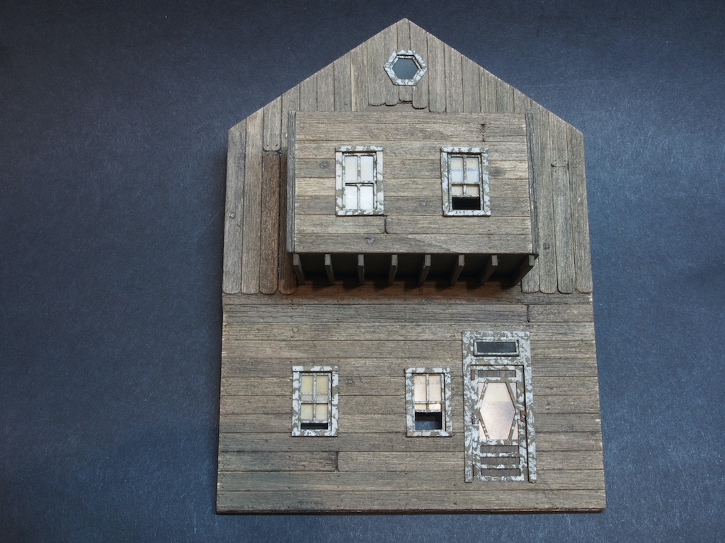
That completes the Left Wall (for now). Here is an overview of this wall to date.
Next, we move on to the Right Wall…
-
6 hours ago, Ian_Grant said:
Oh Glen, if you've never seen Blackadder, especially the Regency and WW I series,
The WWI series was my favourite. You really should check it out Glen.
- mtaylor and Keith Black
-
2
-
Looking forward to seeing an update Mark. Hope you make it through the doldrums okay.
- Keith Black, mtaylor, FriedClams and 3 others
-
6
-
-
Wall Construction – Wall Details (cont’d)
I had a little unexpected free time today, so took advantage of that to continue the build. The awnings are provided on a laser-cut sheet. We initially applied a base coat to this way back in “Advance Preparations”. It is now prepared in the same way as the tar paper, with coat of dull cote followed by some light streaking with chalk.
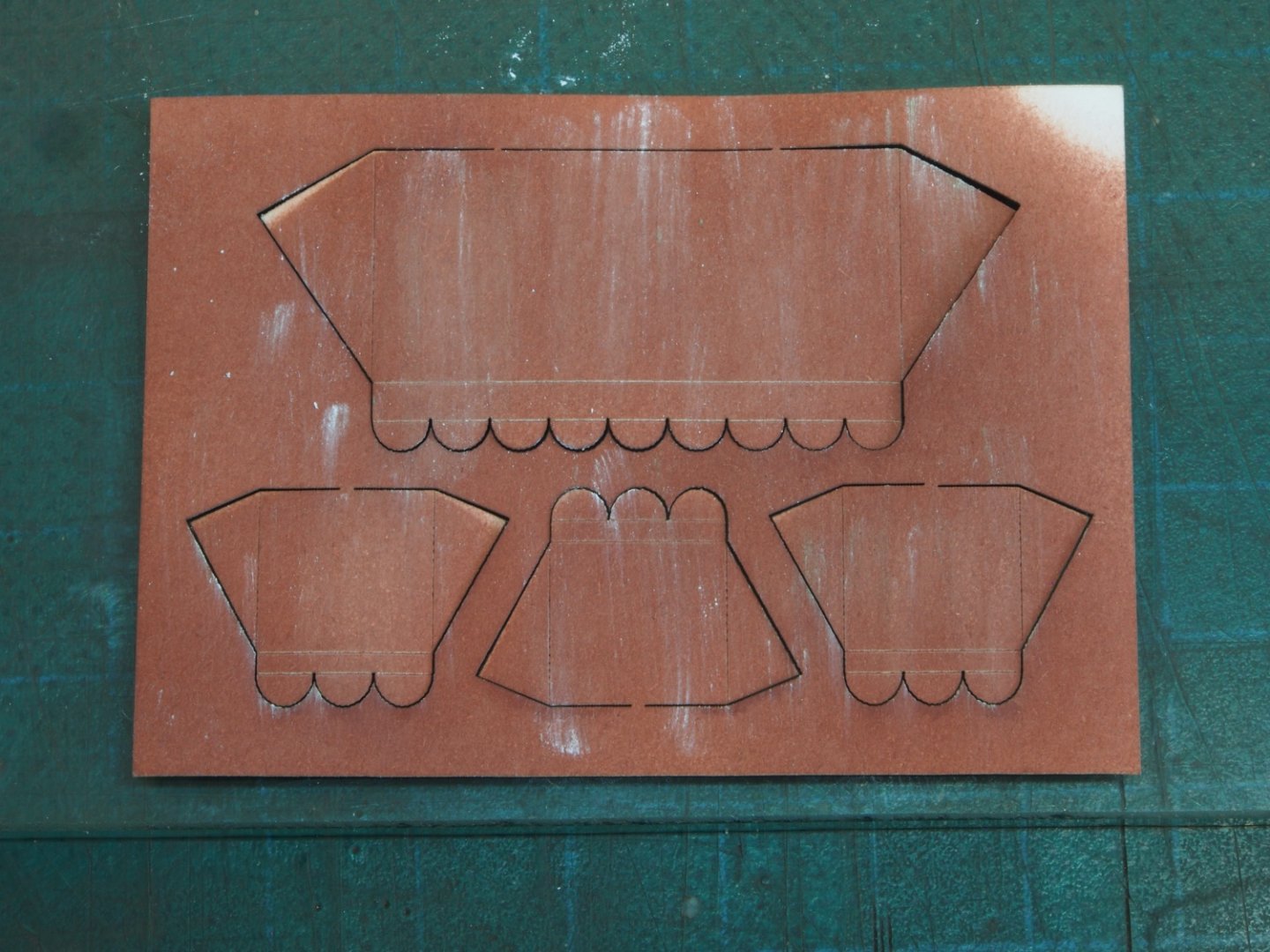
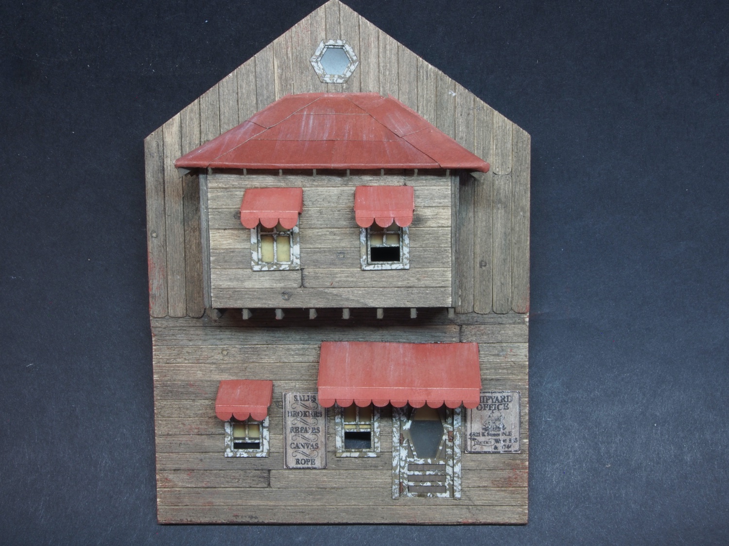
The awnings were then cut free from the carrier sheet and folded along the score lines. A little extra chalk powder was applied to the creases after folding. I used Rembrandt 343.5 for this as it seemed to be a close match to the base coat. They were then glued in place – a delicate but relatively straight forward operation. The signs were then trimmed up and glued in place.

That completes the Rear Wall. On to the Left Wall next…
-
Wall Construction – Wall Details (cont’d)
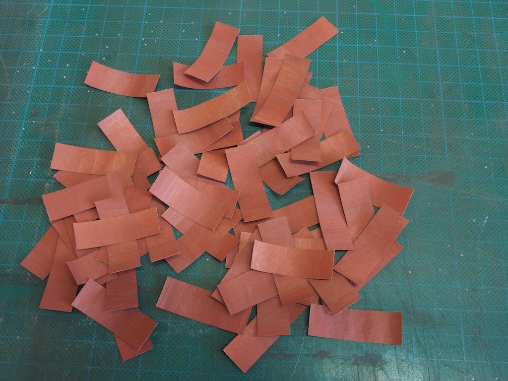
The tar paper is then cut into 1/2” wide strips and then those strips are cut into 1.5” lengths, which are then randomly mixed up.
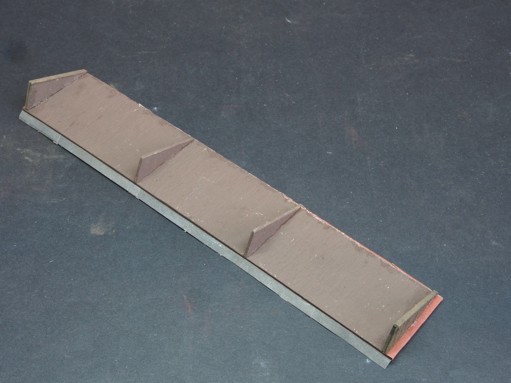
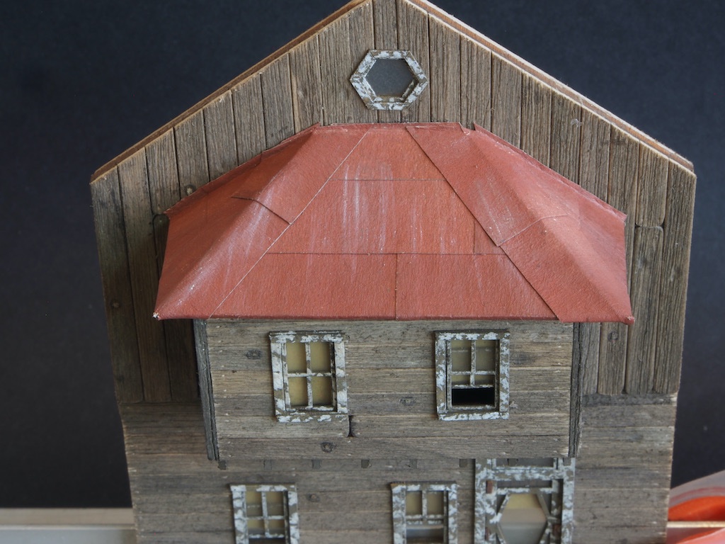
A cardboard substrate is provided for the dormer roof. It is laser cut with the side pieces cut part way through. Laser etched lines aid with the placement of the tar paper and, later on, the rafters.
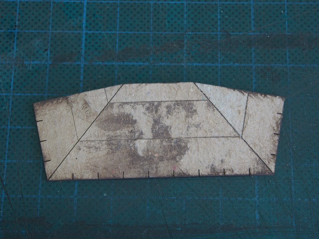
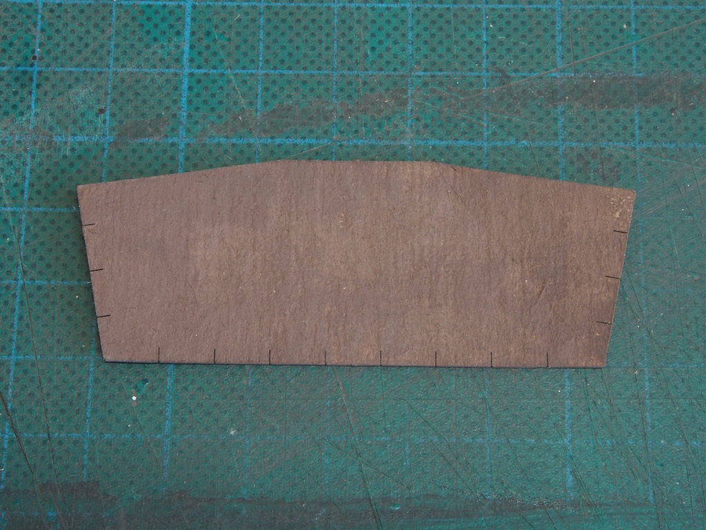
The underside of the substrate is first painted with AK 11110 Leather Brown (my substitute for Floquil Roof Brown).
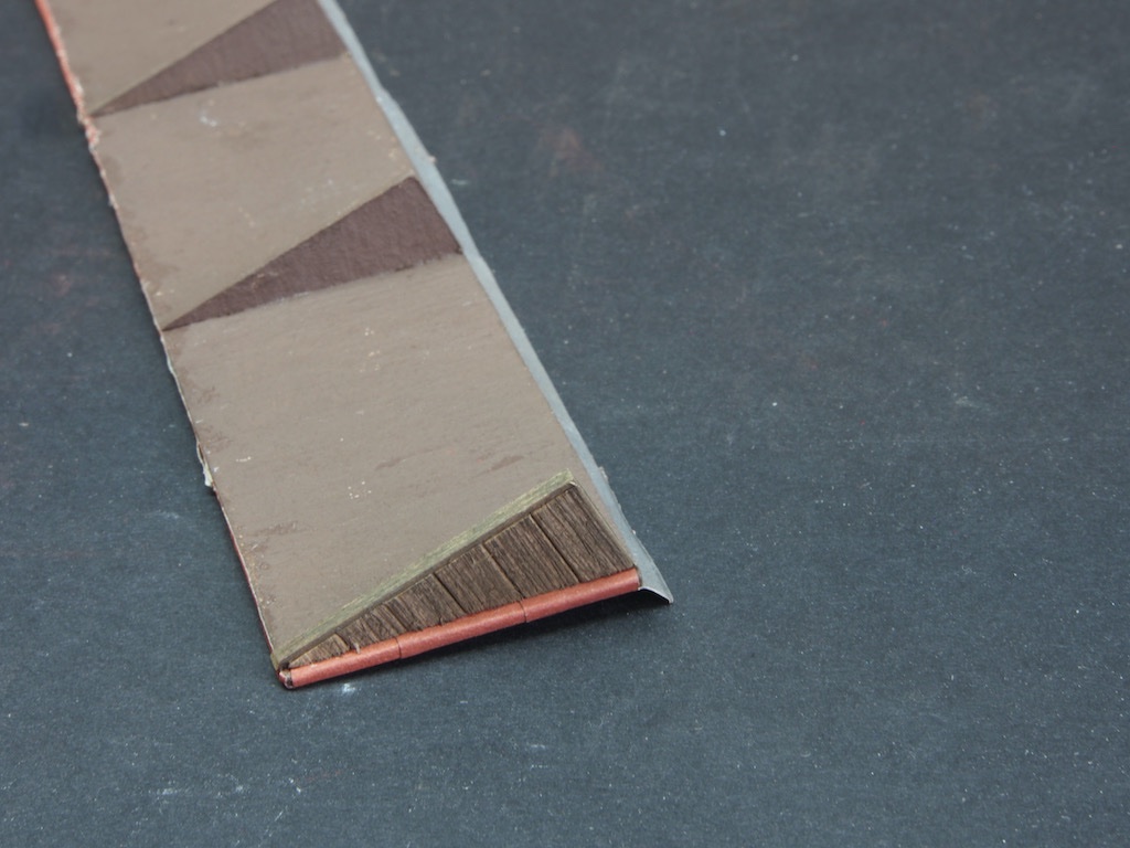
The instructions are well laid out for placing these strips, except that for the third strip (ie the second row) a single piece is called for, and the maximum length specified of 1.5" is not long enough for this span. No big deal, I just added a second piece, being sure to offset the joins from the first row. Here are the strips in place and the roof attached.
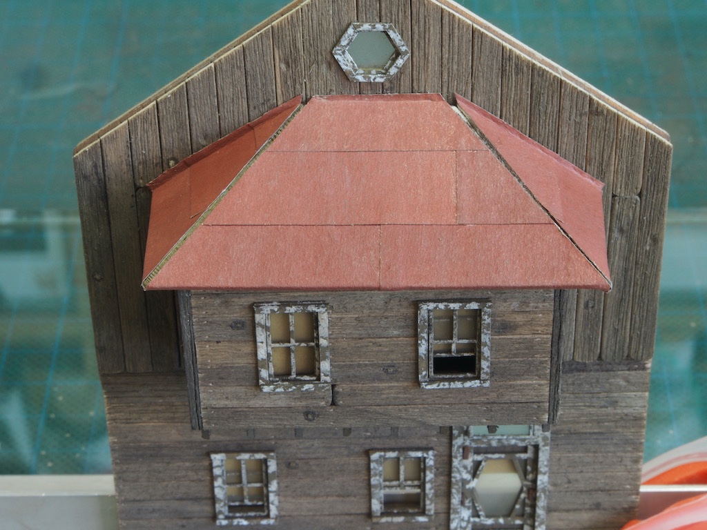
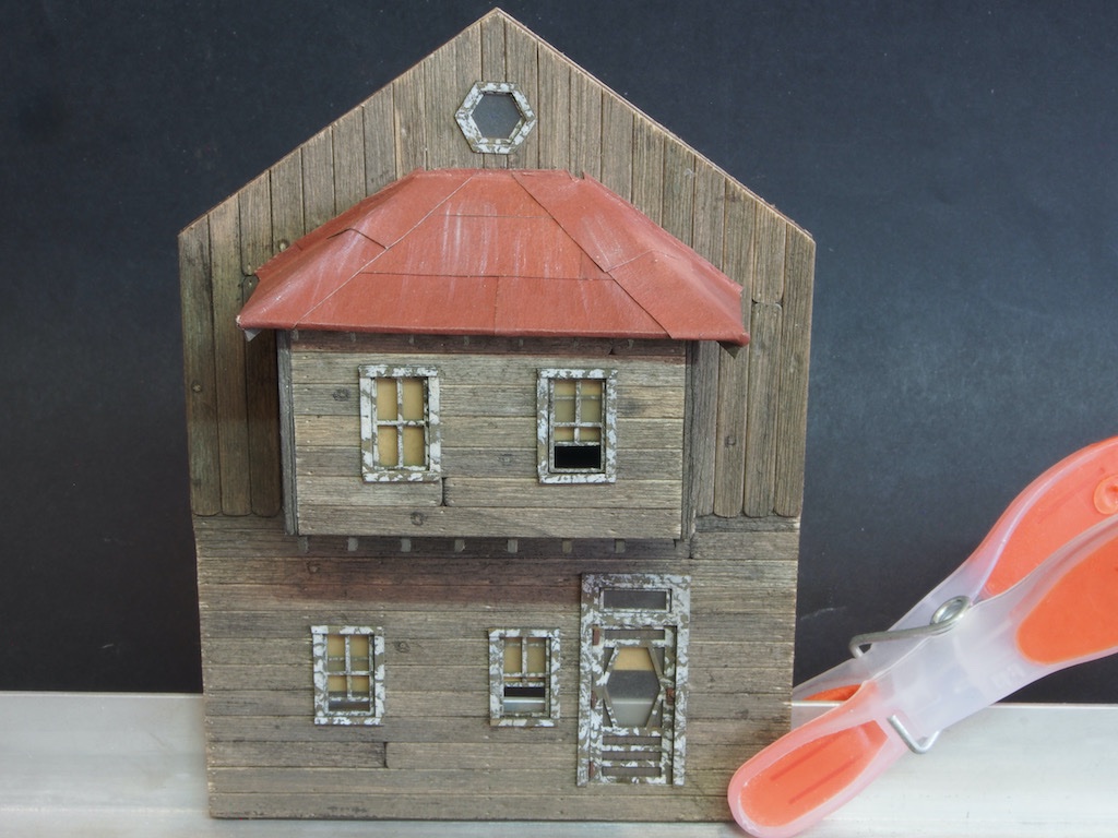
The capping pieces for the peaks are then fitted - a little tricky, but we got there - and some final weathering added. I'm considering adding some "flashing" along the joint with the wall, with a coloured glue mix as I've seen in some other logs.
A special laser cut jig is provided for cutting the rafters to length, with the correct angle on the inboard end (where they attach to the walls). This is a really neat addition that should make cutting the rafters fool-proof. I don't know why, but somewhere along the way I must have made an error in the placement of my roof, as all of my rafters were considerably too long. I ended up adjusting their lengths individually prior to final placement and the end result seems to be okay. I still have no idea where I went wrong.
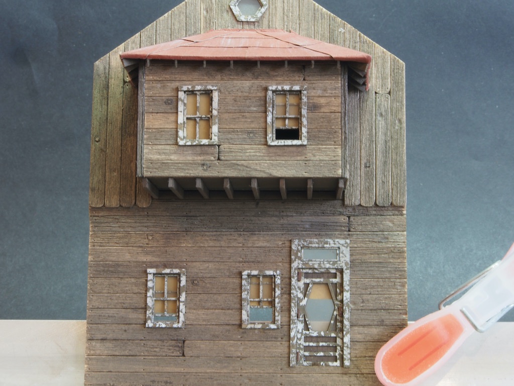
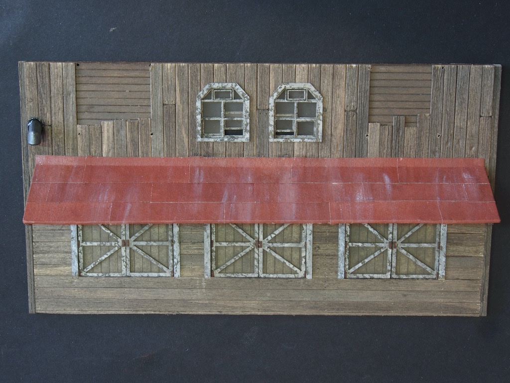
And finally, here is an overview of the wall at this stage.
I still have to add the awnings and place the signs before completing this wall.
-
It's been a few weeks since I updated this log. A week away on holiday followed by a week of life getting in the way has slowed me down a little, but I finally got back to this today. A small update, but progress nevertheless...
Wall Construction – Wall Details (cont’d)
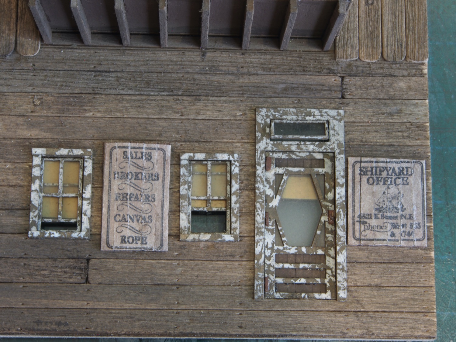
The signs turned out to be not as tricky as I first thought. The signs are provided on ordinary paper and several copies are provided, allowing you freedom to experiment without fear of unrecoverable errors. The first task is to dirty them up using some dry chalk powder and then sand the back of the paper down as far as possible without ripping it. The trick is stopping just short of that point, and not just after it!
Bases for the signs are made by preparing some strip wood in the same way as the walls, and then cutting the appropriate number to length using a provided template. The base boards are then lightly tack-glued together and the sign is then glued to the base. Once dry, the boards are cut apart by carefully bending them back to create a small gap and then inserting a single edge razor blade into that gap and pressing down onto the table until it cuts right through. Once all the boards are cut apart, they are then glued back together. This allows the detail of the individual boards to be visible. Here is the end result – just placed on the wall for context for now.

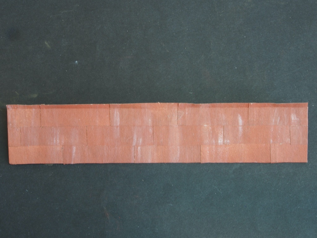
Preparations for the dormer roofs now begin by returning to the tar paper pieces prepared way back in “Advance Preparations”. The painted tar paper is firstly sprayed lightly with Dull Cote (I used an artist matt picture finish). After allowing it to dry for a few minutes, a little white and grey chalk powder are then sprinkled randomly over the tar paper. A soft brush is then used to apply alcohol, brushing in an up and down motion only, to create some streaking. The alcohol reacts with the matt finish and replicates the effects of the sun bleaching out the red colour.
I wasn’t happy with my first go at this and ended up re-spraying the tar paper with paint and repeating the whole process again. Here is how they look as of today.
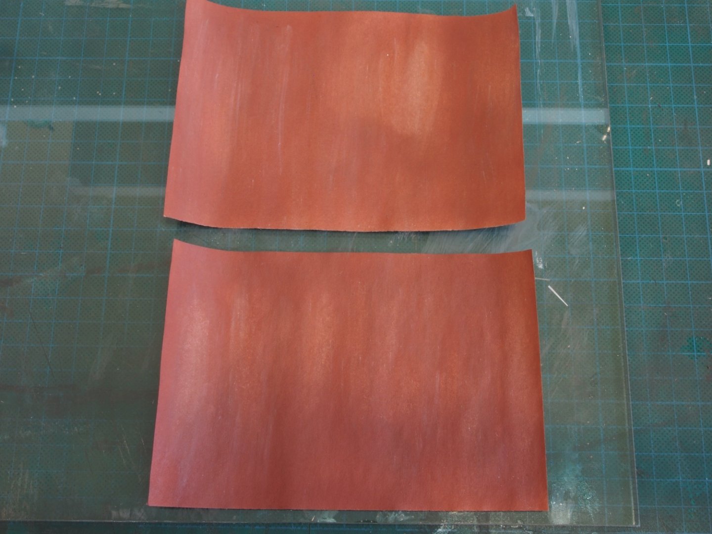
These will now be cut into strips before being applied to the dormer roof. Stay tuned…
-
Best wishes for your surgery and a speedy recovery Bob. We’ll keep a light on for you here.
-
-
-
Fabulous Glen - the rust looks just right.
- mtaylor, Knocklouder, Keith Black and 1 other
-
3
-
 1
1
-
-
-
I somehow missed the start of this project (again!), Glen - but I’m in for the ride now. Glad you found some of the weathering techniques from the Shipyard to be helpful. I’d love to take credit for that, but sadly I was only following someone else’s instructions!
On that note, you really should try the “chalk and alcohol” method for colouring your weathered timbers - it’s dead easy, super quick, and produces great results.
Your progress so far is great. I’m looking forward to following along for the rest of the journey.
- Glen McGuire, mtaylor and Keith Black
-
2
-
1
-
-
-
Congratulations on completing a real masterpiece Chuck. As others have said, inspirational.
- Chuck, FrankWouts, Edwardkenway and 2 others
-
5
-
Wall Construction – Wall Details (cont’d)
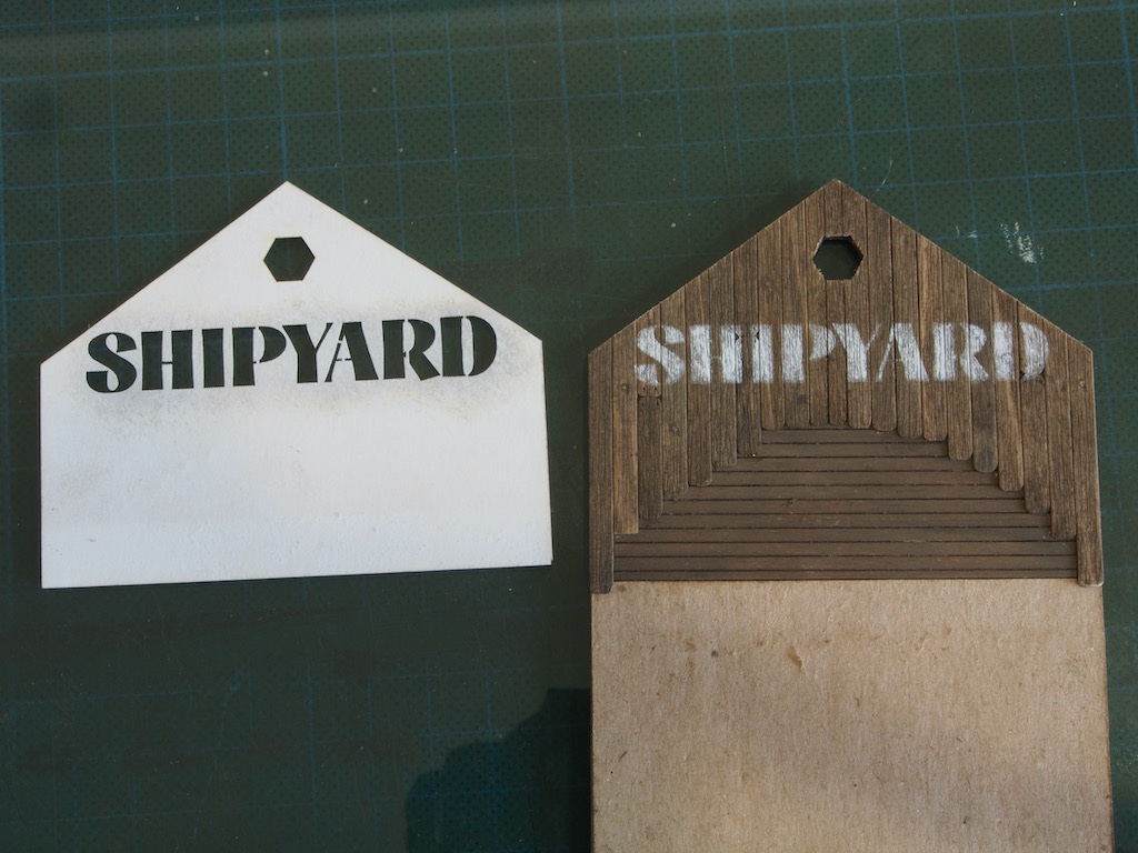
This next job is to apply a stencilled sign to the Front Wall. Although a stencil is provided for this, I was still dreading this particular task. In the end, it turned out a lot easier than I’d expected.
The stencil provided is also shaped to match the wall, so alignment is guaranteed. Nevertheless, I did a practice run on my “crash test dummy” wall first and once I was happy with the techniques, I dove right in. Here is the result after the application of the paint (the first step in the process).
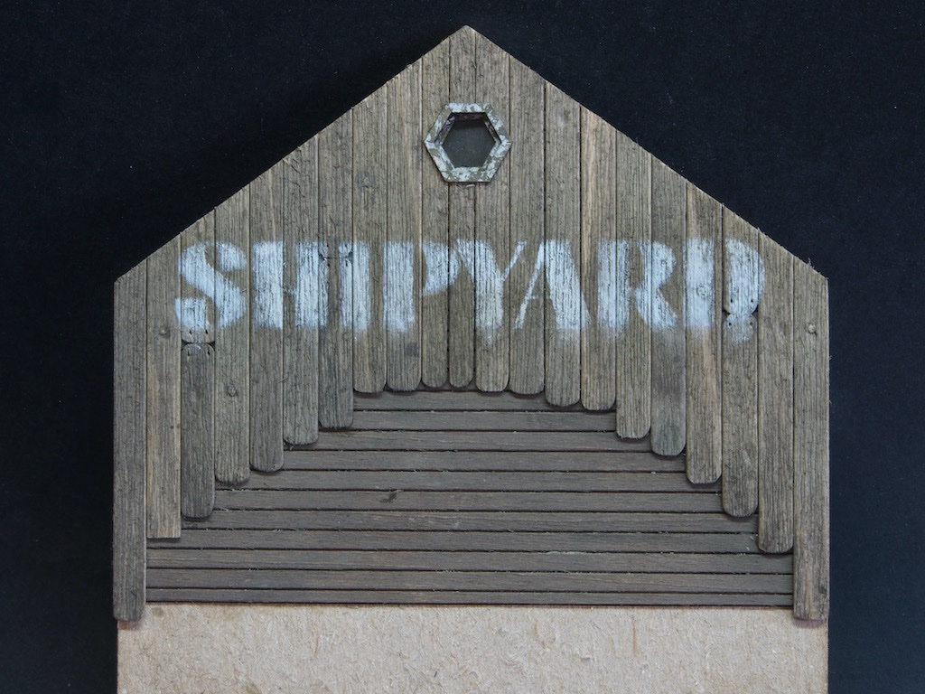
The paint is then toned down a little with a dusting of chalk (in the same way as the windows were treated). The instructions then direct us to “use a small detailing brush to streak a little white chalk powder down the lettering and face of the wall”. I was quite nervous about this step, so back to my test wall for practice. I was glad I took this step because my first attempt was waaaay too much white chalk. With that as a gauge, I tackled the real thing and was fairly satisfied with the result. The instructions emphasise that “less is more here”. Here is the end result, complete with attic window fitted.
We now return to the Rear Wall and start by making up and installing the windows and doors. As this process is exactly the same as previously described, I won’t repeat the details here - except to note that the transom window on the door has been left ajar just for Glen...😉
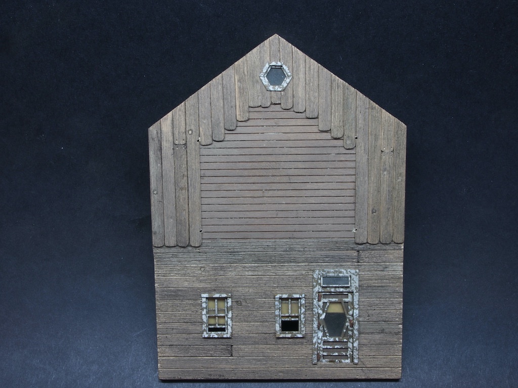
We now get to install the Dormer on this wall. Another clever design feature of this kit is the inclusion of some very small laser cut holes in the substrate that are used to align the Dormers. We are invited to punch through these holes and through the applied siding with a sharp object. I opted to use a small drill to avoid the risk of splitting the siding. I also decided to attach a piece of scrap wood along where the bottom of the Dormer will sit to avoid having a gap here (since the Dormer will sit on the siding along it’s sides).
With the Dormer safely installed, it's time to add the floor joists for the Dormer. The kit provides a paper template and gives instructions for using this to create the Floor Joists. I opted to use the template to mark a scrap of wood and then cut this and checked it against the template again before using it to set a stop on my Chopper. That quickly gave me the eight required joists of identical length and all with perfectly square ends.
I used the soft jaws of my Proxxon vice to hold the wall upside down while I attached the joists. In this photo, you also get a glimpse of just how messy my modelling desk is at the moment!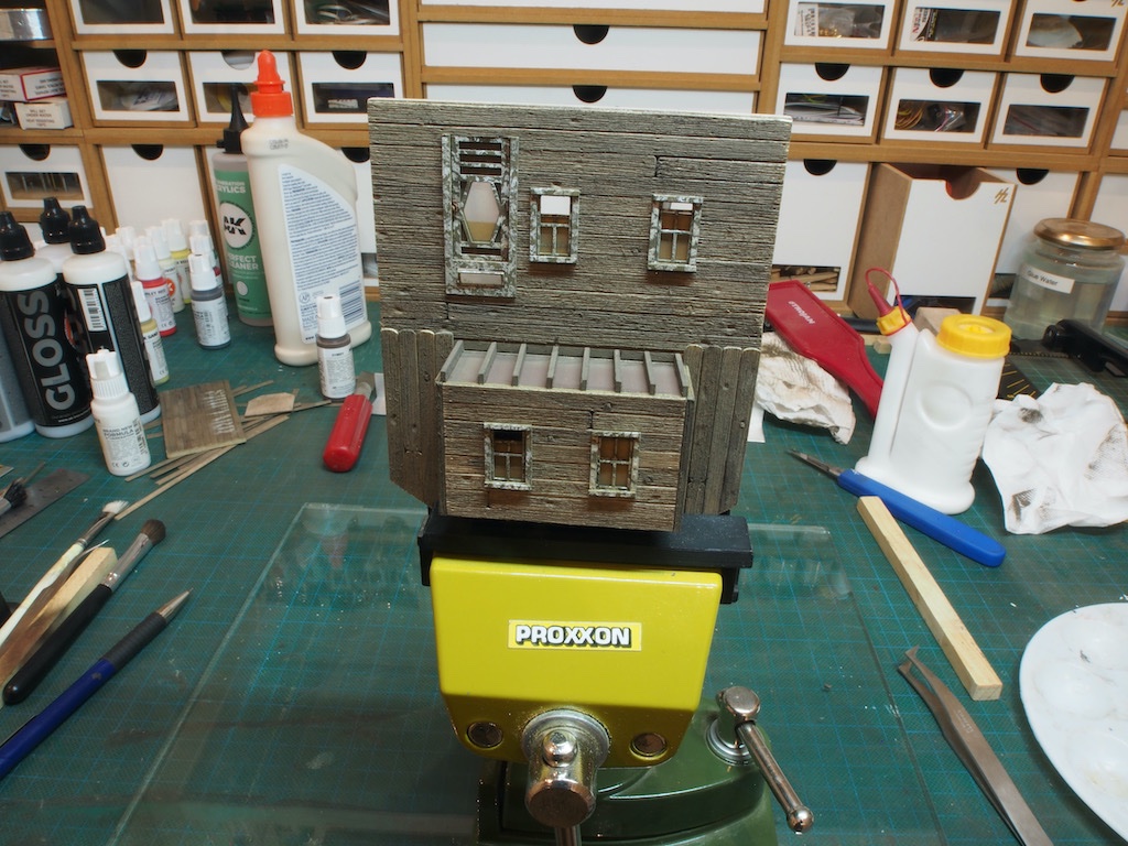
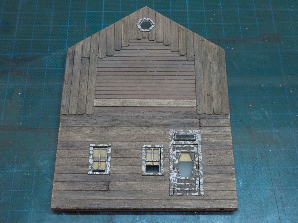
And here is the wall at the close of play today (minus the background clutter).
Another terrifying task awaits me tomorrow when I will tackle the Signs…
-
That’s exactly right Glen. In the manual they are referred to as “pop-out” windows. An option when installing them is to position one or more of them partially open. I opted not to at the time, but kinda wish I had now. To go back and try to change that would be too high a risk of damaging things though, so they’ll have to stay closed.


The Shipyard at Foss' Landing (Diorama) by gjdale (Grant) - FINISHED - SierraWest - Scale 1:87 (HO)
in Non-ship/categorised builds
Posted
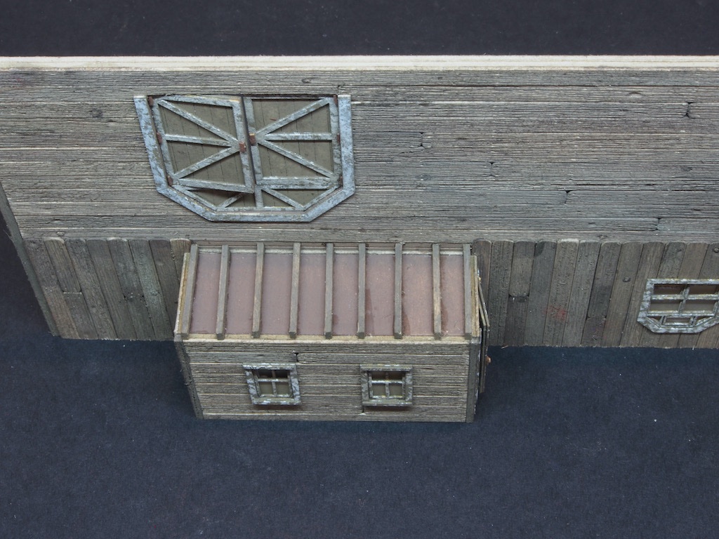
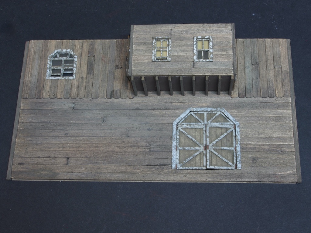
Wall Construction – Wall Assembly
With the walls complete, they were assembled – in pairs initially – with the aid of my magnetic gluing jig and some small clamps.
The two sections were then glued together as a single structure. Here are a few shots going around the building.
Two braces are added to the base, to make the structure more rigid and to help keep everything square. A view block is also added by means of a piece of black card cut to fit.
Another pair of braces are added level with the top of the side walls, and then the ridge beam is glued in place.
Roof Construction
The roof substrate is a laser-cut piece of card with some clever engineering to help with placement of the shingles (more on that later). The underside and edges are painted first, and the roof card is then glued in place. At this point the two right wall Dormers are also glued in place.
Joists are then added to the underside of the Dormers as previously done for other dormers.
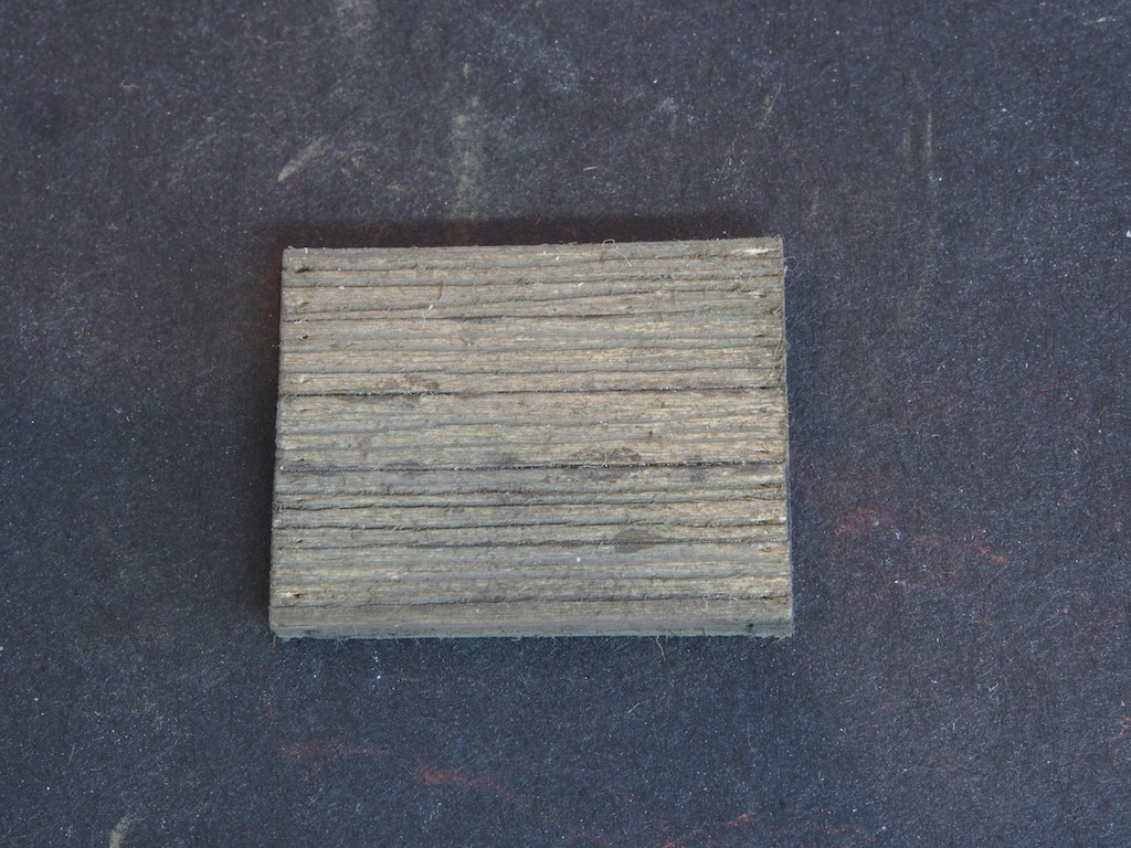
Shingles are provided in the form of laser cut paper strips on carrier sheets. These had a preliminary preparation way back at the start under “advance preparations” when they were given a light spray of AK11008 Grimy Grey (my substitute for Floquil Earth).
The shingle strips are now cut from the carrier sheets and individually treated with chalk and alcohol. The basic procedure is to scrape some raw umber chalk (Rembrandt 408.3) over the strip, then blot with a soft round brush dipped in alcohol. A little white chalk is immediately scraped on top, and the same brush used to blot and blend most of it in.
Once all these strips have been so treated and are dry, a stiffer, dry brush is used to blot some grey chalk (Rembrandt 408.9) randomly on top. This gives a nice, aged appearance with some natural variations between strips. Some leftover solid scraps from the carrier sheet were also saved and treated in the same way as these get used for part of the shingling process.
Now for the clever part of the roof design.
The lines visible on the roof card are actually strips that peel away to reveal adhesive beneath. We begin by measuring and cutting a plain strip (from the scrap), and then lifting the first row of adhesive and placing the strip. This additional strip, lifts the first row of shingles off the roof in a very prototypical way. The first row of shingles is then measured, cut, and glued on top of this row. I forgot to take a picture of the first step, but here is the first row of shingles in place.
After this first row, strips of shingle are simply measured, cut and placed by simply revealing the next row of adhesive. The protective paper on the row above acts as a guide to but the shingle layers against. The strips of shingles are also provided with an even number of whole and half shingles on the ends, so it is easy to alternate rows such that the rows of shingles are staggered.
Here is the second row in place.
And the third row.
And here is the first three rows in place across the entire side of that roof.
I could be at this for a while yet…