


gjdale
-
Posts
4,819 -
Joined
-
Last visited
Content Type
Profiles
Forums
Gallery
Events
Posts posted by gjdale
-
-
Thanks Glen, Sam and Egilman, and again to all of the likes.
Moving right along...
Wall Construction – Dormer Details (cont’d)
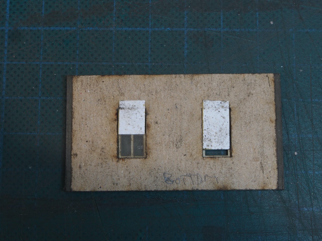
This Dormer has a door that will open onto a landing atop a set of stairs. We begin by giving the door pieces all the same “peeling paint” treatment as the windows.
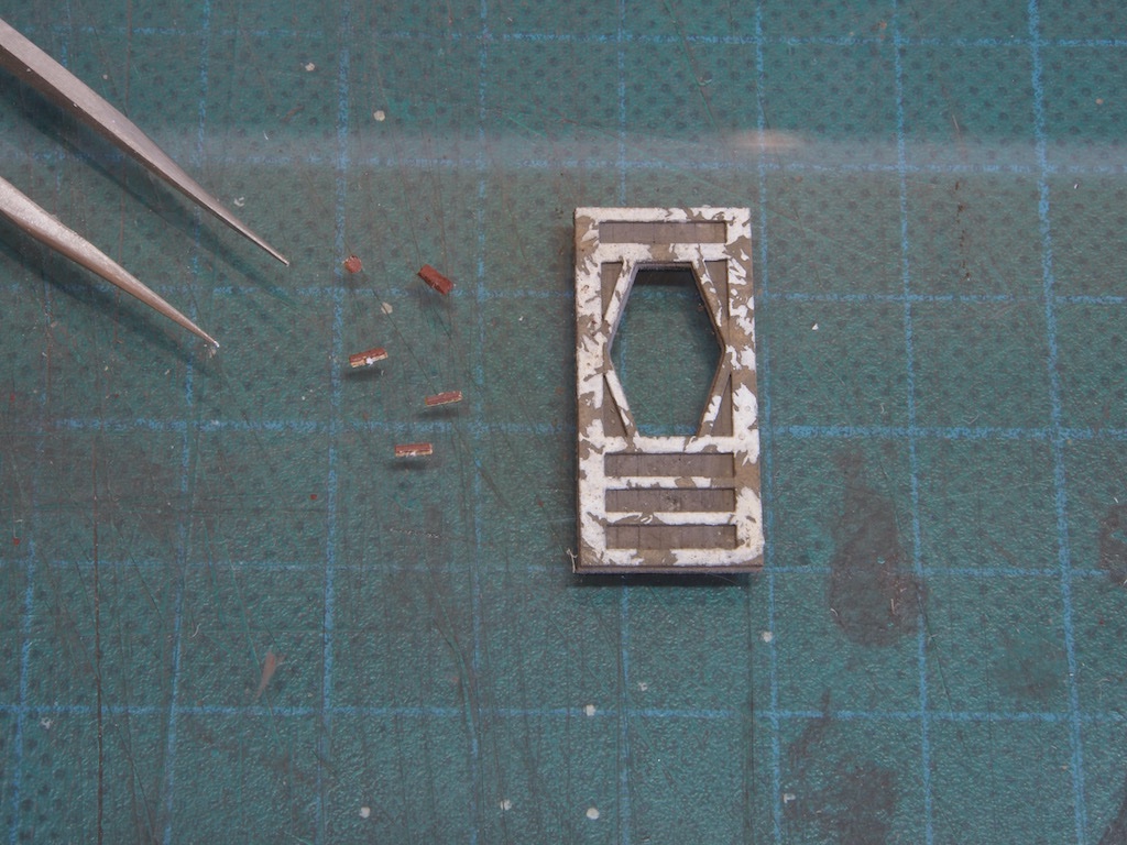
The hinges, door knob plate and door knob all get a coat of paint (AK11110, Leather Brown in lieu of Floquil Roof Brown). We are then instructed to “dust a little rust chalk powder on them”. The instructions don’t mention the exact colour for the rust, but earlier in my Sierra West log, a couple of the “gurus” had mentioned that Rembrandt 411.3 was their “go to” rust colour, so I went with that.
Here they are with the points of my tweezers for scale reference. These things are tiny!
And here they are attached to the door, with the mylar window glass also in place.
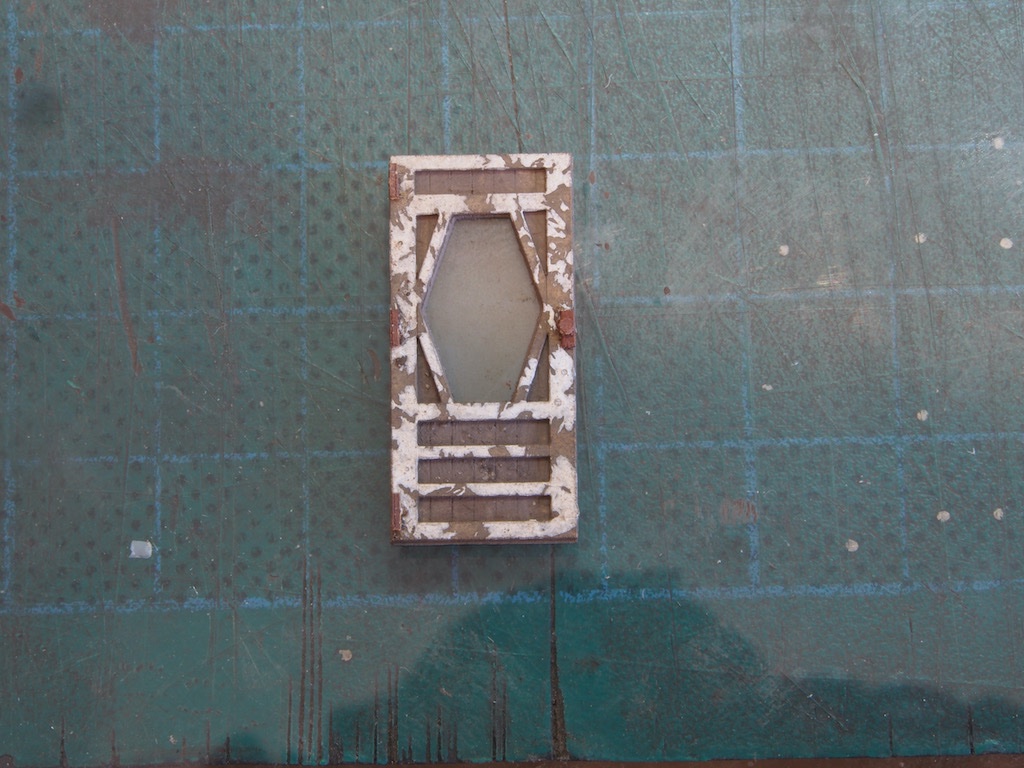
The door is then glued to the wall and the outer frame attached. I followed a suggestion in the instructions and left the door slightly ajar.
The three walls are then glued together, taking care to keep them level and square to each other.
The next step is to fit both a floor and roof piece inside the wall structure, which will give the whole thing much greater stability. However, I have encountered an issue that I have sought some extra guidance on before committing to this step. I’ll update here once I’ve resolved that one.
-
Thanks very much Ken and Sam, and also to all of the "likes".
Wall Construction – Dormer Details
The next step in the instructions invites us to add some nail holes to the Left Dormer wall. Now, nail holes in the model railroad world are a bit like treenails in the model ship world – a big can of worms with arguments about what is realistic and visible at certain scales. Just as we would argue that treenails on a ship’s hull would be largely invisible at 1:87 scale, so too in the model railroad world are the varying schools of thought about adding nail holes in walls. Some advocate for the maximum detail, others say “not at 1:87 (HO) scale”. To further confuse the issue, the instructions say to add them with the point of a compass, while the kit designer himself says he doesn’t generally add them in HO scale, but provided the option in this kit for a bit of variety.
So after prevaricating for several days, I built a “test wall” from some scraps and tried out two different methods. In the picture below, I have used a sharpened mechanical pencil to make the nail holes/heads on the left, and a needle point instrument to make the nail holes on the right.
I was initially drawn to the more obvious variation on the left, but after putting it out for some opinions on the Sierra West Forum, one of the “gurus” suggested that if done on the entire wall, that version would become overpowering. I decided to heed that advice and went with the “less is more” solution.
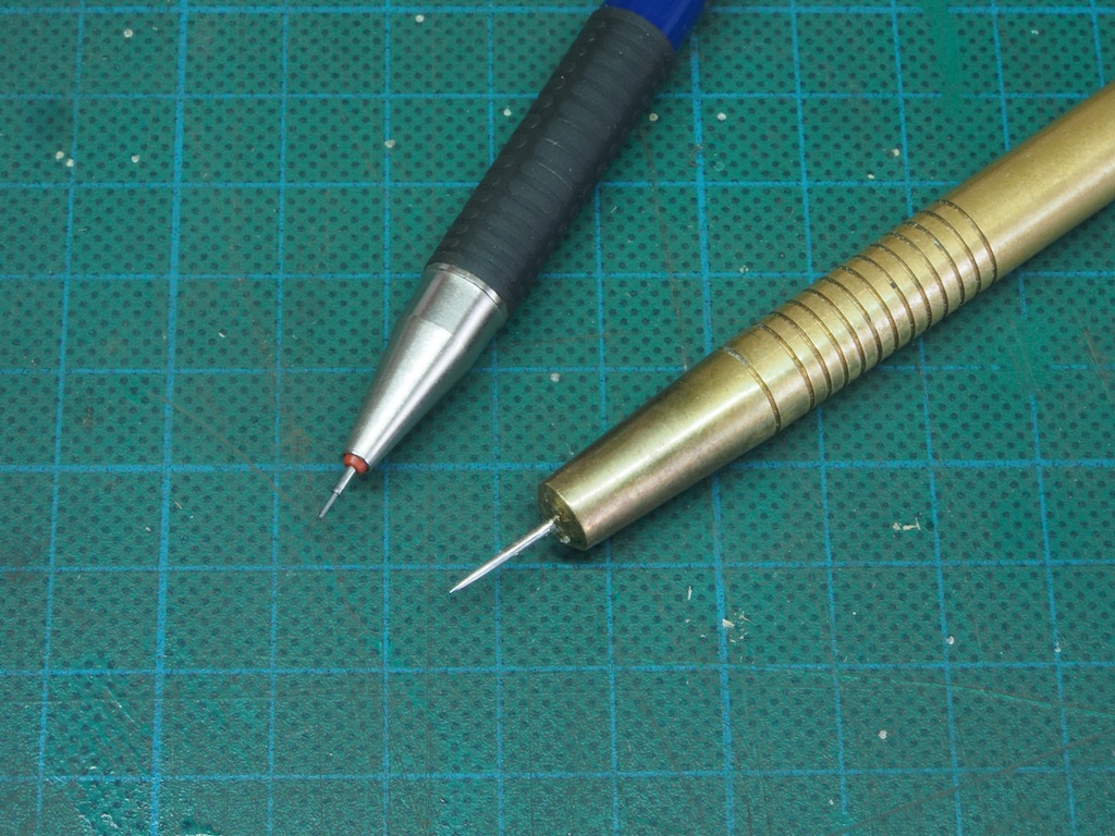
My “nail gun” for inserting these was a home-made scribing tool - a piece of turned brass with a large sewing needle epoxied into the end. The weight of the brass gives this quite a bit of heft and makes the job a lot easier. Shown here next to a mechanical pencil for scale.
I went ahead and added nail holes to all of the walls. Here is few shots showing the completed nail holes.
The nail holes are there if you look for them, but they aren’t immediately obvious. I believe this is as it should be and is what the “gurus” were trying to get across to me – the art of subtlety.
Moving on now with a little more confidence, albeit still at a glacial pace! Corner trim was added to either end of the Left Dormer Wall. The windows for this wall were then prepared in the same fashion as the main windows, including the final stage of dusting with dry chalk powder to tone down the white paint.
We are then instructed to make some window blinds by painting some plain paper with Floquil Depot Buff and then dirtying it up with some chalk powder. My substitute paint choice was AK 11033 (Dark Sand) and again I used Rembrandt 408.3 chalk powder for the “dirtying”, applied in the same way as the final stage of the window frames (ie a dry dusting).
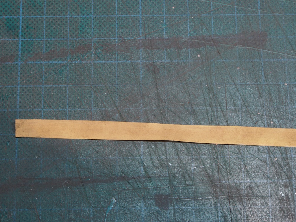
The strip was then cut to length for individual window shades of varying length and glued in place on the inside at the tops of the windows.
The outer window frame was then added, with separate headers and ledges added as the final touch to give a greater 3-D effect.
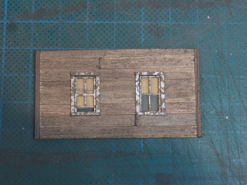
That completes the windows for this wall. The door for this Dormer will be next – quite a challenge with some tiny hinges and a door knob to add as well….
-
Thanks OC and Ken, and also to all of the "likes".
Wall Construction – Main windows
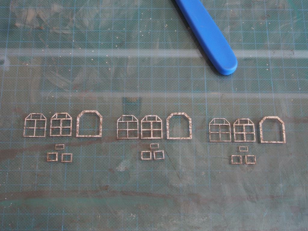
The main windows are constructed in a very similar way to the freight doors – they are just a whole lot smaller….
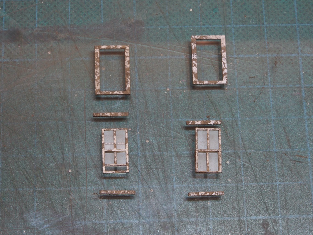
The windows are comprised of a base, trim, and frame plus two separate lower sashes per window and one very small “pop out” window that goes in the top of the window. Here are the pieces for the three main windows, after receiving the same treatment as applied to the door pieces earlier. The blue object in the top of the photo is the handle of my scalpel, which might serve to show just how tiny some of these pieces are!
We are next instructed to “locate the sheet of laser cut mylar”. A brief moment of panic while I rummaged through the box without finding said sheet. Then I remembered that I had in fact seen it before, and sure enough there it was, hiding in plain sight within Bag #5 among other “miscellaneous” items. Heart attack over, we are instructed to spray a light, even coating of Testors Dull Coat over the window pieces. I didn't have Testors Dull Coat to hand, but I did have some permanent matt spray finish for artists. As it claims to be suitable for all papers and boards, artwork, transfer lettering etc, I figured it must be pretty much the same stuff. And indeed it seems to have done the job just nicely. After allowing it to dry for a few minutes, it was again given a light dusting of chalk powder to give the windows a "dull and muddy look, but not so much that it looks painted". To quote again from the manual, "you are looking to represent years of dirt and grime build-up". So here is the sheet after that treatment. (Three of the lower sashes had already been removed before I remembered to take a photo).
The lower sashes then have their mylar "glass" installed by peeling off the backing on the sash and carefully applying the mylar. Here is a close-up of one sash after receiving it's glass.
The remainder of the mylar "glass" was then installed and the sashes and "pop-out" windows installed. Following the instructions, I've placed the lower sashes in a varying degree of open positions. At this stage I haven't added any cracks or holes in the windows - as the instructions note, this is a working structure, so I'm inclined not to add these.
Next, we return to the Dormers to add some more detail….
-
Thanks for that additional tip Andy. I'm sure there are many ways to skin this particular cat. One of the reasons I like the method I've been following, is that so far, everything has been both relatively easy and relatively quick.
So, I had just posted the pics from my last post on the Sierra West forum and one of the “gurus” there gave me a great tip to tone down the white paint a little – it does look a little stark as is, despite the peeling effect.
His tip was to use a soft brush and very lightly dust some DRY chalk powder onto the white to dull it down and age it a little. Nothing ventured, nothing gained right?
Here is a “before” (on the right) and “after” (on the left) following that advice.
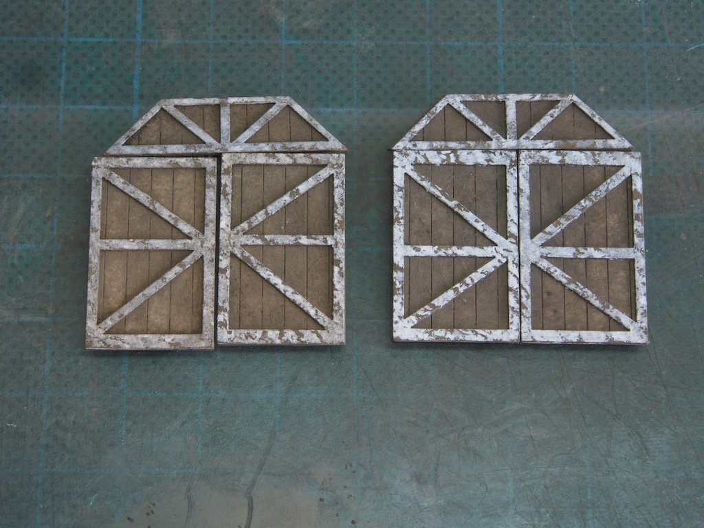
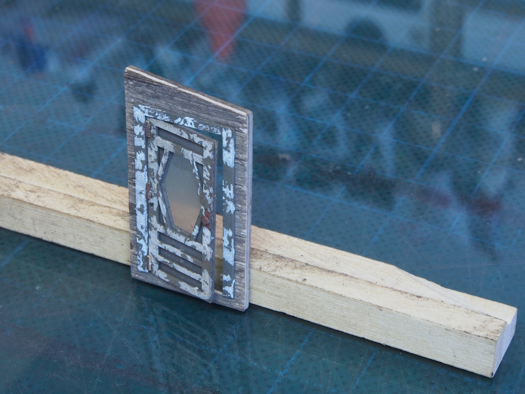
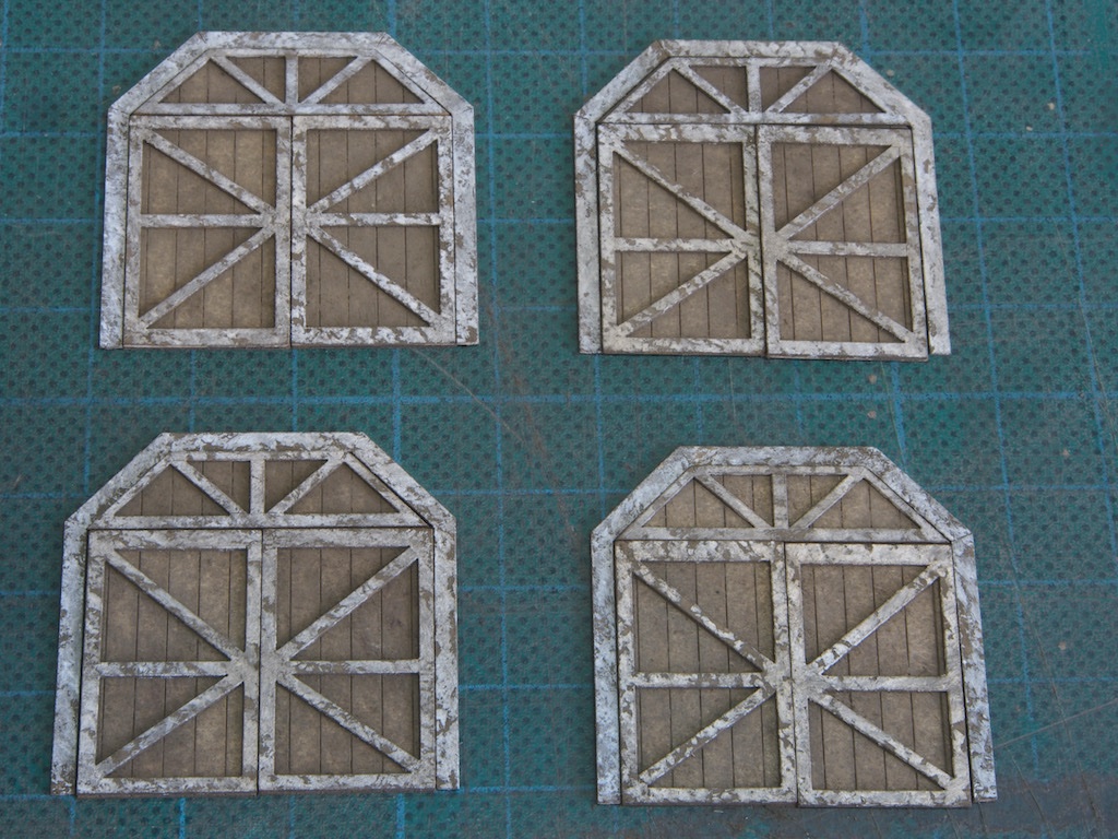
I think I like that even more! Here are all four doors, with trim permanently attached and blended down.
And finally, following the earlier advice, here is one of the doors placed temporarily in situ.
Okay, now I’m ready to tackle the windows….
-
Glad to hear it worked out for you Peter. The postage hurts now, but you'll forget that as soon as you start using the tool!
-
Thanks Keith and Ken. Moving on...
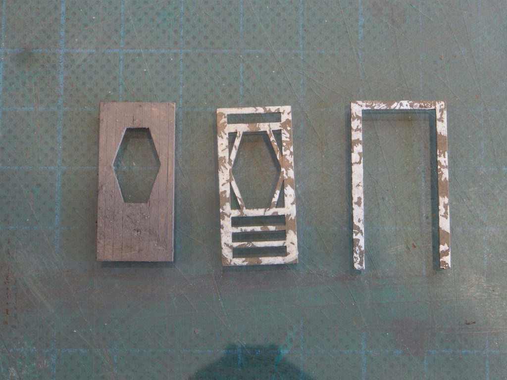
Wall Construction – Doors
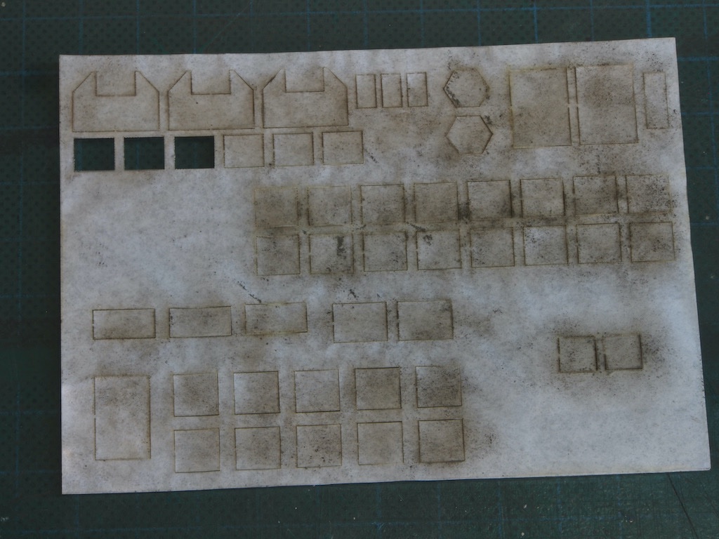
There are some really clever design features in this kit, which makes both construction and visual effects relatively easy. The material used for the door and window frames is a special resin impregnated paperboard that will not warp, is very flexible and accepts paint and chalk nicely. It also has an adhesive backing that is pressure sensitive so that it may be moved slightly after placement, before pressing down to make a permanent bond.
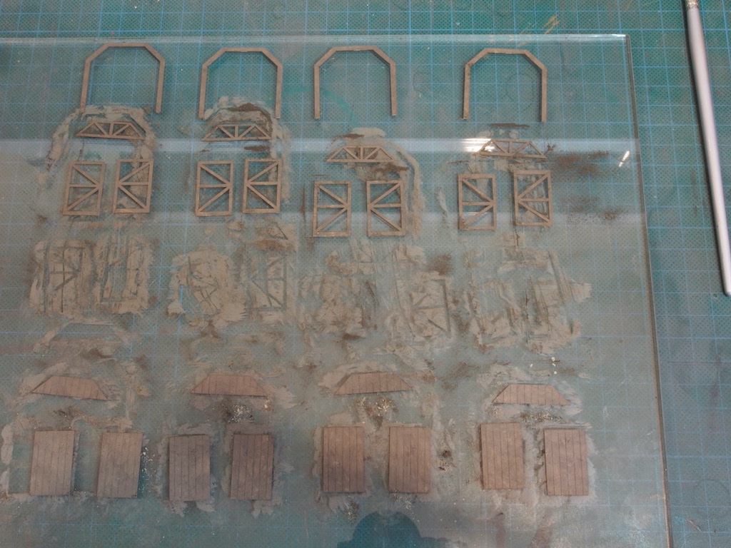
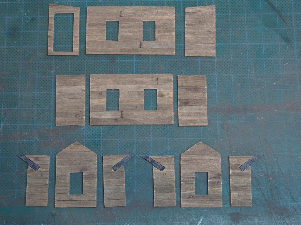
Here is the laser cut sheet containing all of the door and window frames.
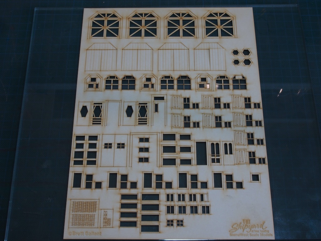
Each of the four freight doors is comprised of seven component pieces (not including the six hinges and two handles that will be added to each door later).
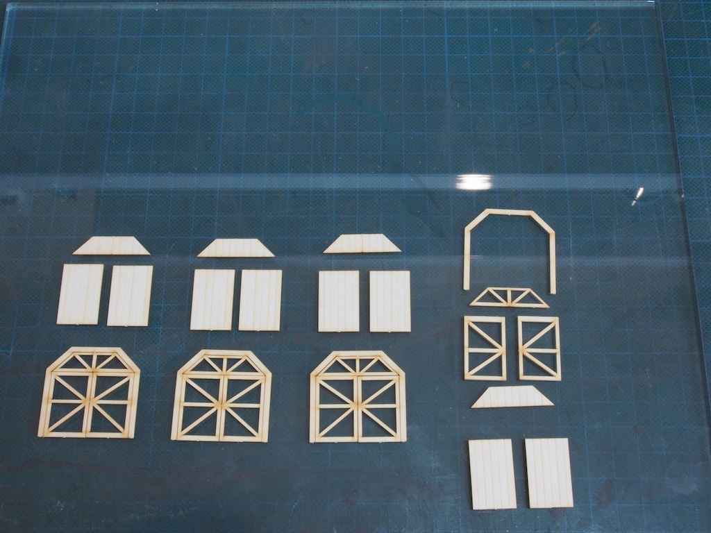
To go with the dull and naturally weathered siding, we want to achieve a peeling paint effect on the door and window frames. To achieve this, a base colour is first applied to all of the pieces, in the same way as was done for the walls.
Here is that process in progress:
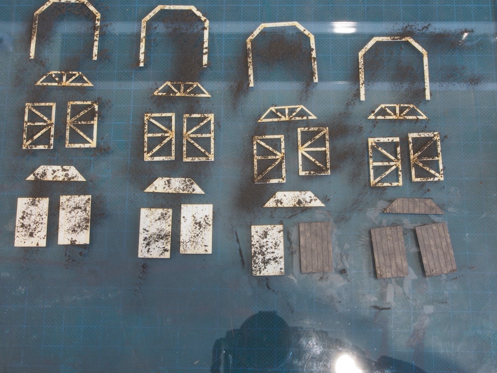
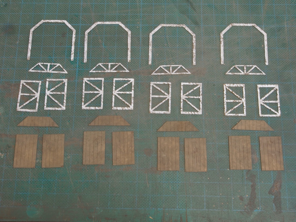
The base pieces (the lower, solid pieces in the bottom of the photo above) are then given a second coat of chalk/alcohol, this time adding some colour variations to bring them close to the final colours in the walls.
White paint (I’m using AK 11001 White as my substitute for Poly Reefer White) is then applied to the frame and trim pieces using a very stiff bristled brush to very lightly blot the paint onto them. I found the best approach was very similar to a dry brushing technique – dip the end of the brush into the paint and then dab most of it off on a piece of paper towel before very lightly blotting onto the pieces. This ensures that not too much paint is applied, which would spoil the mottled effect replicating the peeling paint.
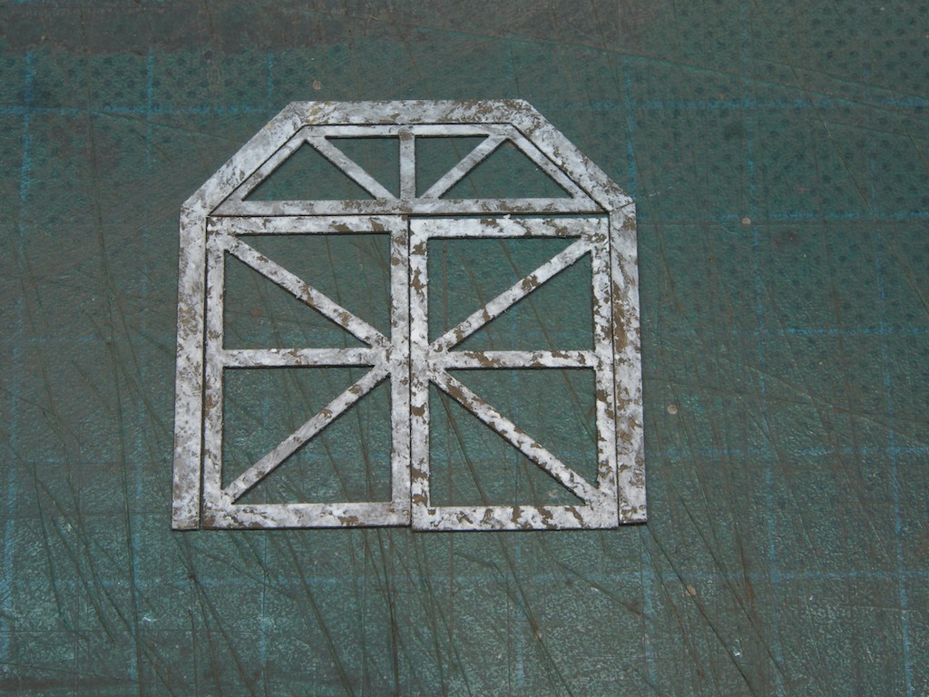
Here is a close-up of one set of frame and trim pieces:
To gauge the overall effect, all of one of the door pieces were placed temporarily (ie loose) into a wall opening.
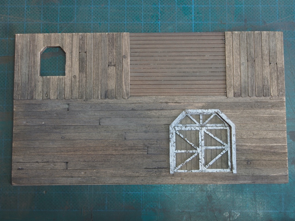
I’m happy with that as an overall effect, so will now proceed with permanently attaching the frame and trim pieces to the doors.
- Jack12477, FriedClams, Glen McGuire and 14 others
-
 15
15
-
 2
2
-
-
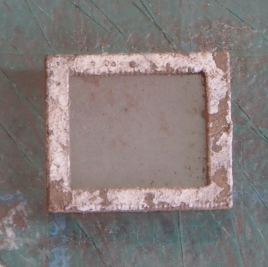
Wall Construction – A Minor Repair
So I had some feedback overnight from the sharp eyes on the Sierra West forum that a mark on one of my walls could be “repaired” by removing and replacing that plank. I’ve circled the offending area in the photo below.
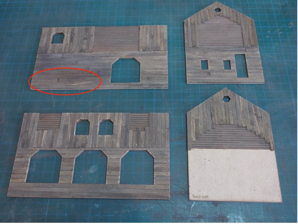
The mark is a natural variation in the timber but wouldn’t disappear with any amount of chalk/alcohol/ink mixture. It was bugging me, so I’m glad someone else saw fit to make a constructive comment.
I was a little concerned about potentially doing more harm than good in a repair by replacement approach, so I sought some extra guidance from the experts over there. They very helpfully came back with a detailed explanation of the recommended procedure, along with pictures to illustrate. The method is essentially the same as removing a plank from the hull/deck of a ship model – apply isopropyl alcohol to de-bond and gradually lift and separate. I had been concerned that applying extra IPA might damage the existing board finish on the rest of the wall, and/or the underlying card substrate. I needn’t have worried!
I started at one end by applying IPA with an old paintbrush and slipping the point of a #11 blade under the plank.
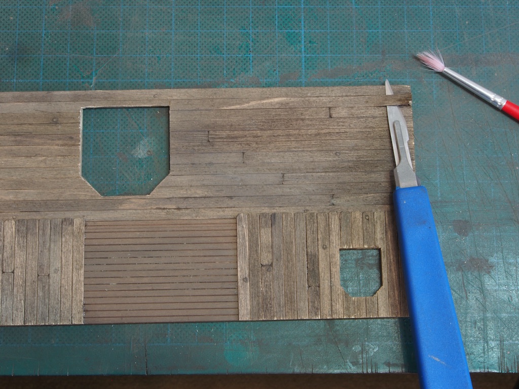
Once I had the tip inserted, it was easier to get more IPA into the joint. I also scored the plank where it met the side of the doorway. Here we are about half way through:
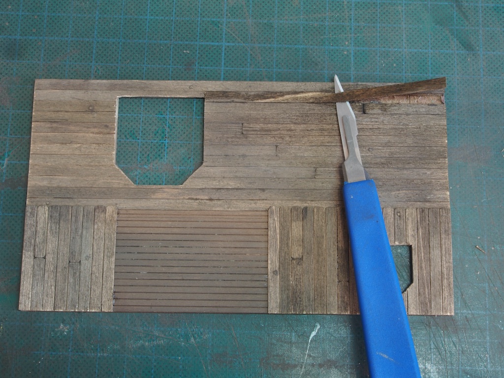
And with the offending plank finally removed:
And after a little extra clean-up with a riffler file and the trusty #11 blade:
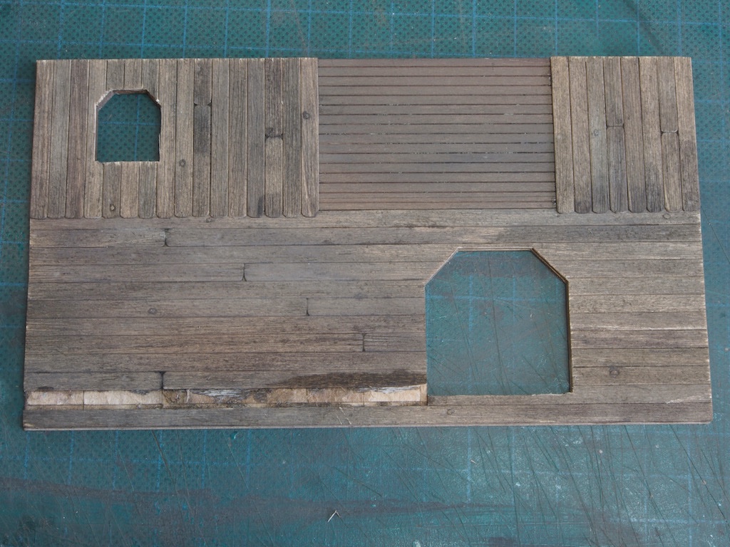
And with the new plank installed and trimmed to fit.
Much better! I’m glad that this has happened at this point as it now gives me confidence for any other (perhaps inevitable?) re-work further down the track.
Wall Construction – Dormers
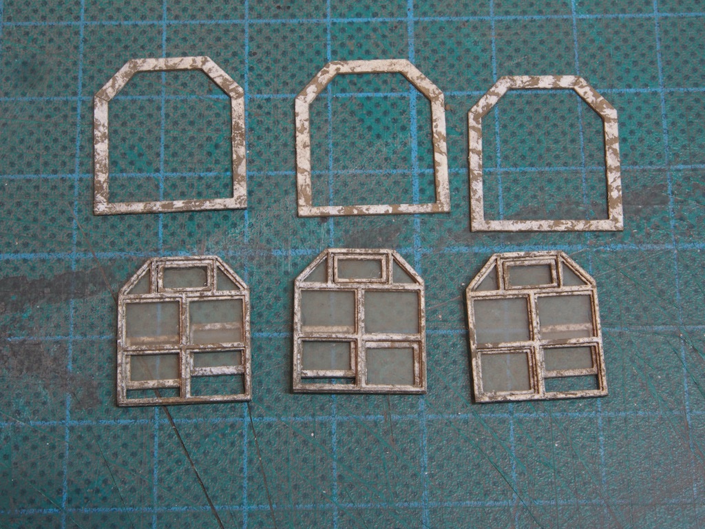
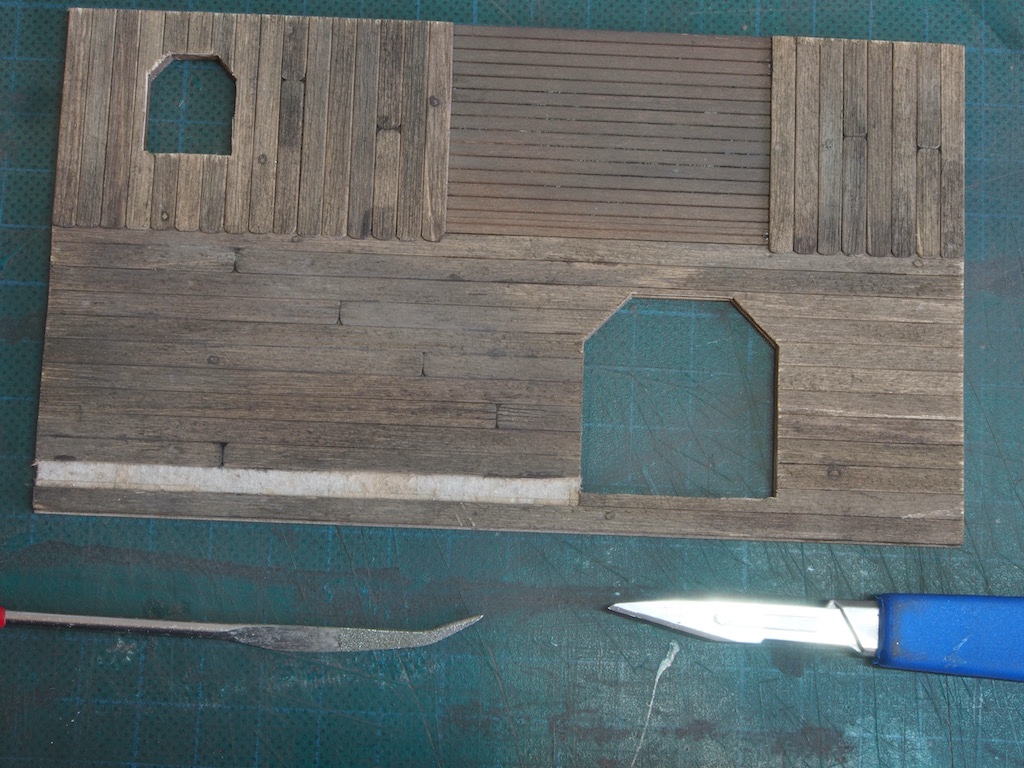
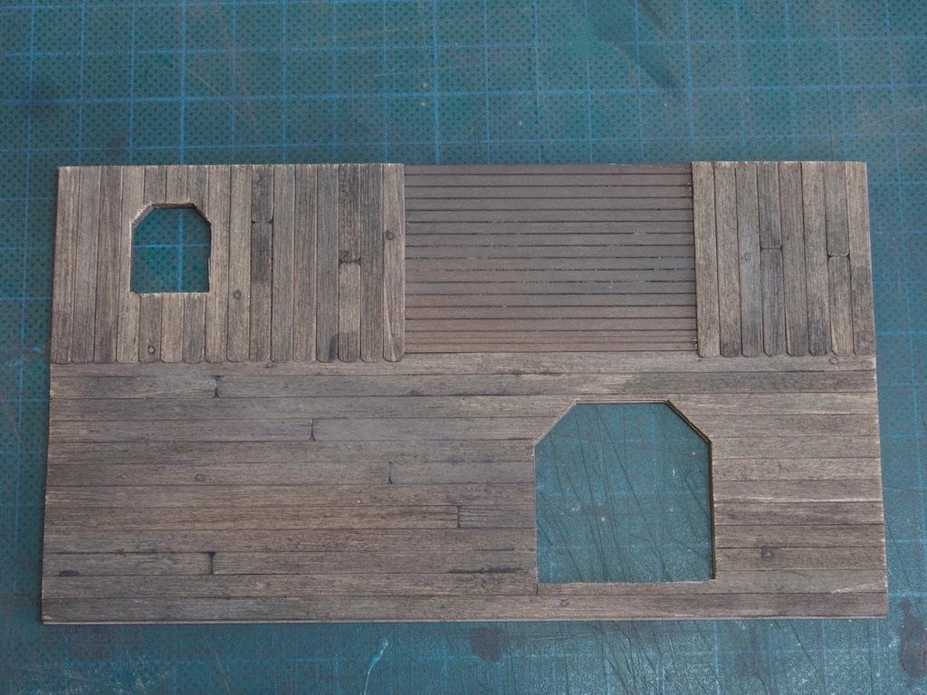
Construction of the Dormers follows essentially the same process as the walls, with the exception that there is a small amount of flashing to be added. The kit design is rather clever in how this is achieved. The flashing pieces are laser cut along with the dormer side walls and left in place connected by two very small tabs. The process is to remove the flashing pieces, plank and trim the remainder of the side wall, paint the flashing, and then reinstall it into the side wall and voila!
Here is a picture of the side walls having been planked and trimmed, and the flashing pieces ready for re-insertion. Since flashing was usually lead strips back in the day, as the exposed lead aged it dulled and darkened. To achieve this effect, painting the flashing pieces comprises three steps. Firstly, a base coat of Floquil Grimy Black is called for. My substitute of choice here is AK Basalt Grey. Once this is dry, the piece is dry brushed with Polly Oily Black. My substitute of choice here was Vallejo Glossy Black. I’ve never dry brushed anything before but have watched several videos of it being done, so I just jumped in and had a go. The final step was to give the piece a light dusting with grey chalk powder. It’s very hard to see in the photo, but I believe I’ve managed a reasonable facsimile.
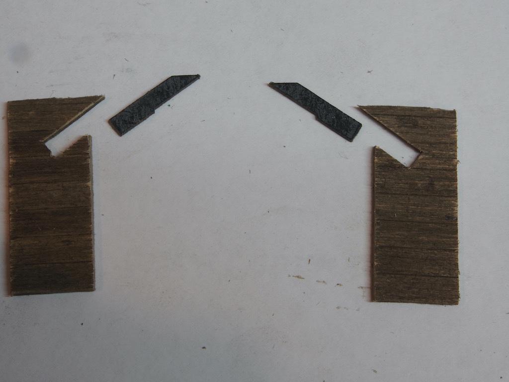
The pieces are then glued back in place, flush with the back side of their respective walls.
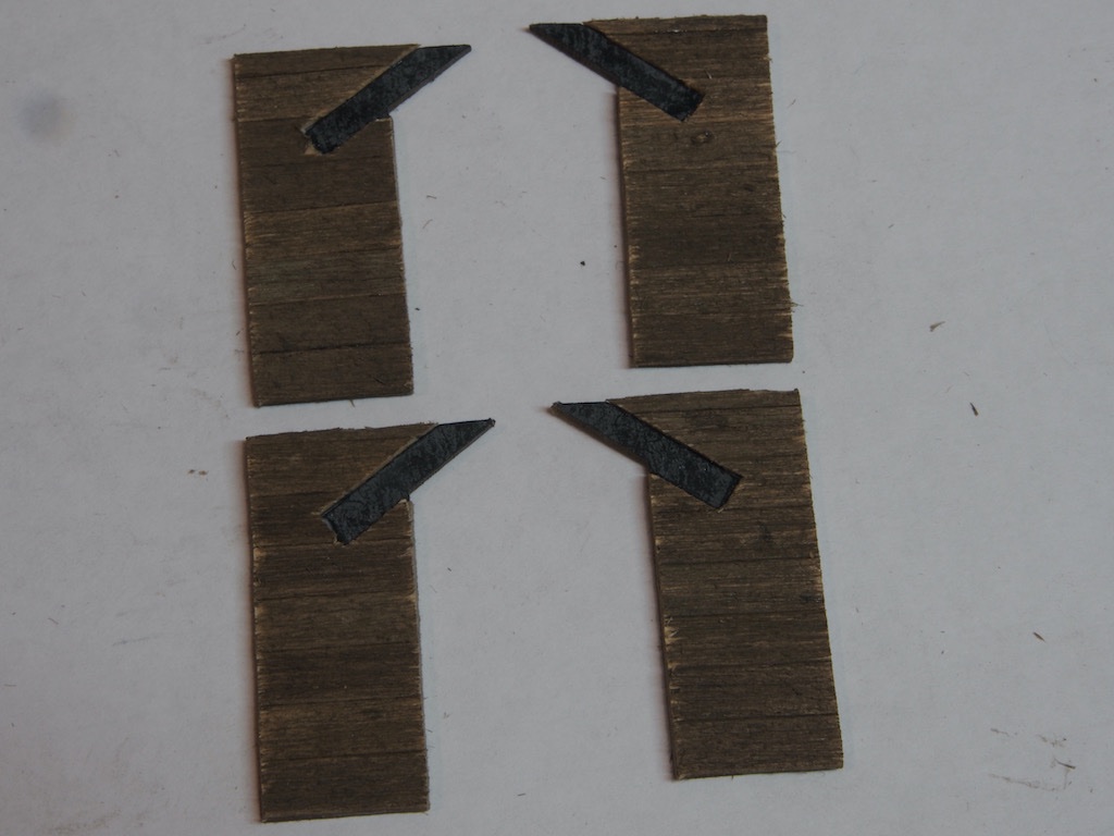
And finally, here is a shot of all the Dormer pieces ready for the next step, which will be the laser cut doors and windows.
- FriedClams, Glen McGuire, mtaylor and 14 others
-
15
-
2
-
Absolutely stunning work. Thank you so much for sharing this beautiful work with us mere mortals!
- mtaylor and billocrates
-
2
-
Thanks Glen, Keith and OC.
OC - the answer is, I'll tell you when I get there..... Joining the walls together starts on pg 30 of the manual - I'm currently at pg 13. There is a lot of work yet to do before then. Reading ahead, there are braces added, but I may end up adding additional bracing. Will have to wait and see how sturdy it looks/feels at the time.
Keith - it will be a very large bottle of single malt Scotch. Not for placing the model inside of - purely to help the builder along the way!
-
Thanks for all the comments and likes folks. It seems to be a while since I updated this log - the usual excuse of "life" getting in the way. Anyway, I've been progressing slowly and finally have something worth posting.
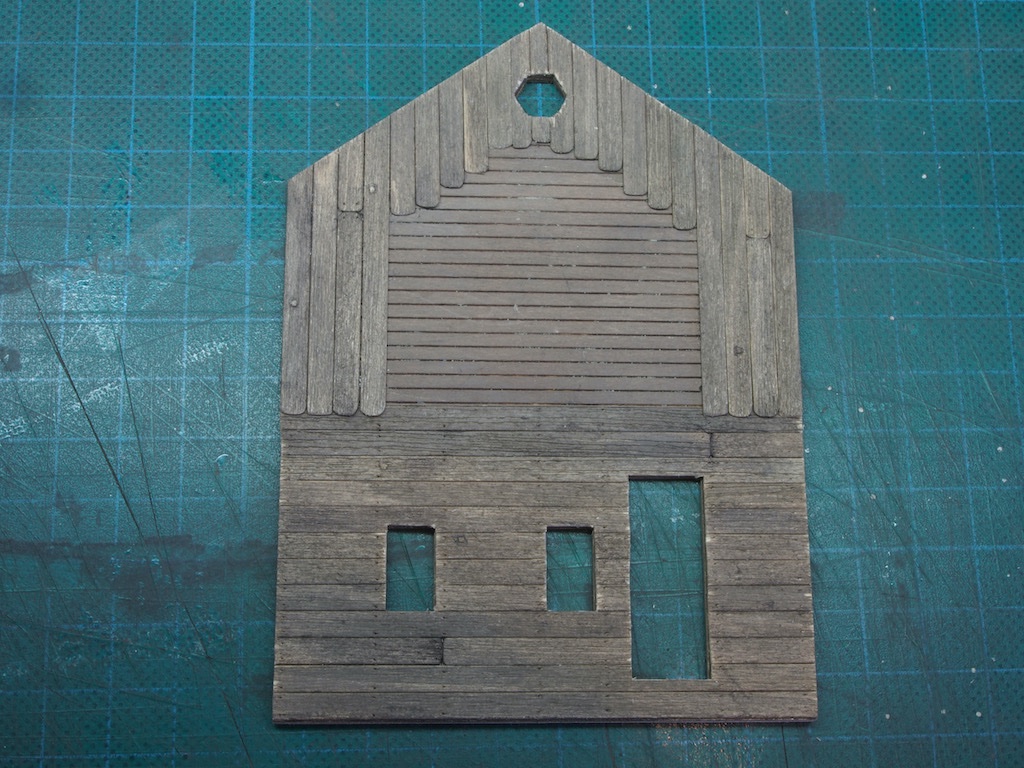
Wall Construction – Adding the Siding
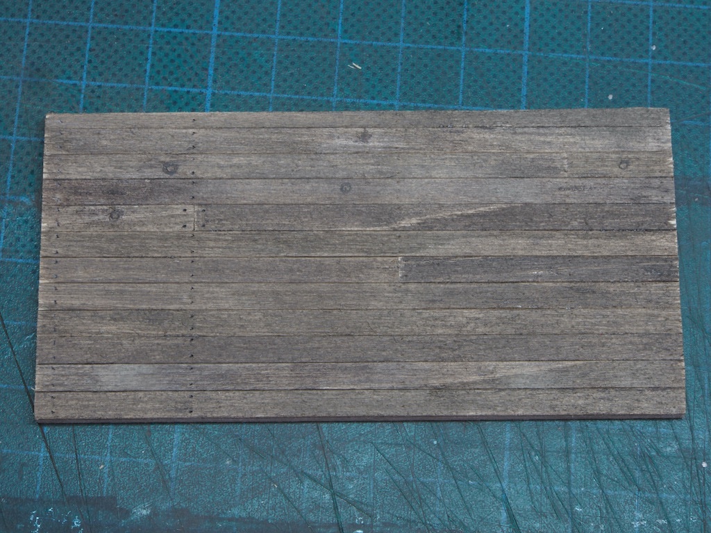
With the board detailing complete, it was time to add the siding to the walls. This commences with laying one complete board on the Right wall. This is butted against the slight overhang created by the upper floor, ensuring that the board is straight and even.
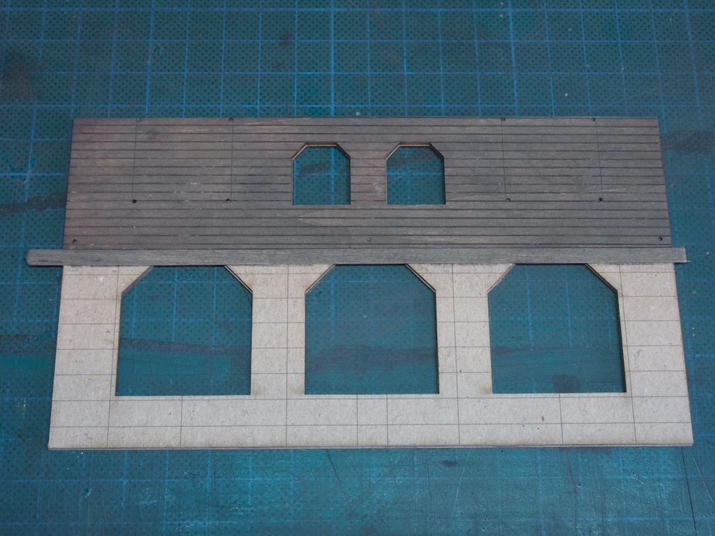
Boards were then selected randomly and glued in place using the horizontal scribed lines as an aid to ensure they were straight. All boards were left long and slightly covering the window openings, to be trimmed up later.
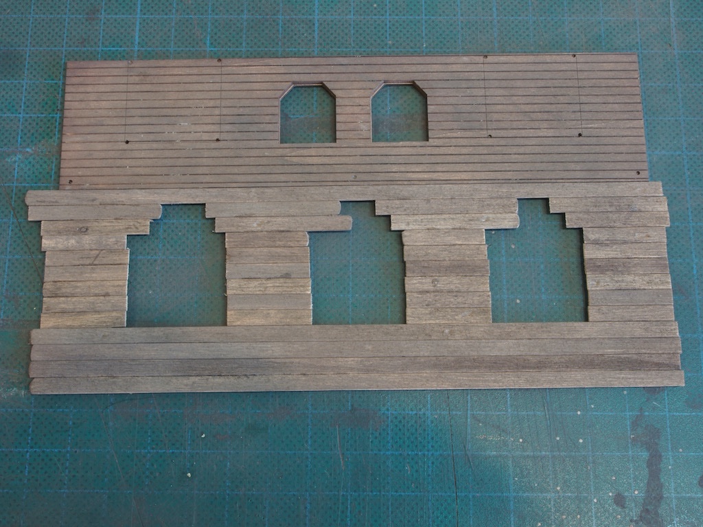
The same process was followed with the remaining walls, this time also using the vertical scribed lines as a guide to placement of butt joints.
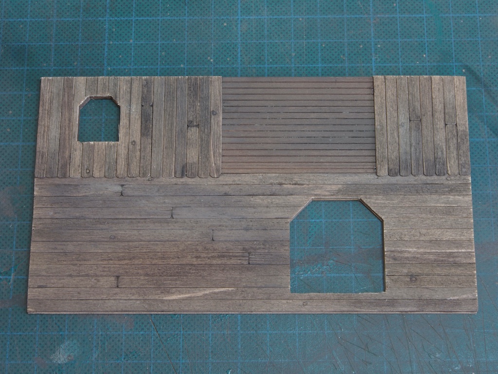
Here are the three walls with horizontal siding attached. Once I’d finished these, I noticed that on the Left wall (top left in the picture below), I could see the untreated card around the gaps in the butt joints. I decided to go back in and add some alcohol and chalk to darken these up, but this then left a noticeable dark patch around the joints.
To remedy this, I went over that section of the wall very lightly with a wire brush again, applied a very light wash of alcohol/ink mixture and dabbed a variety of chalk powder randomly over that section.
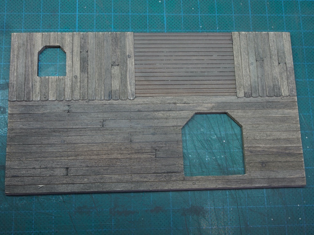
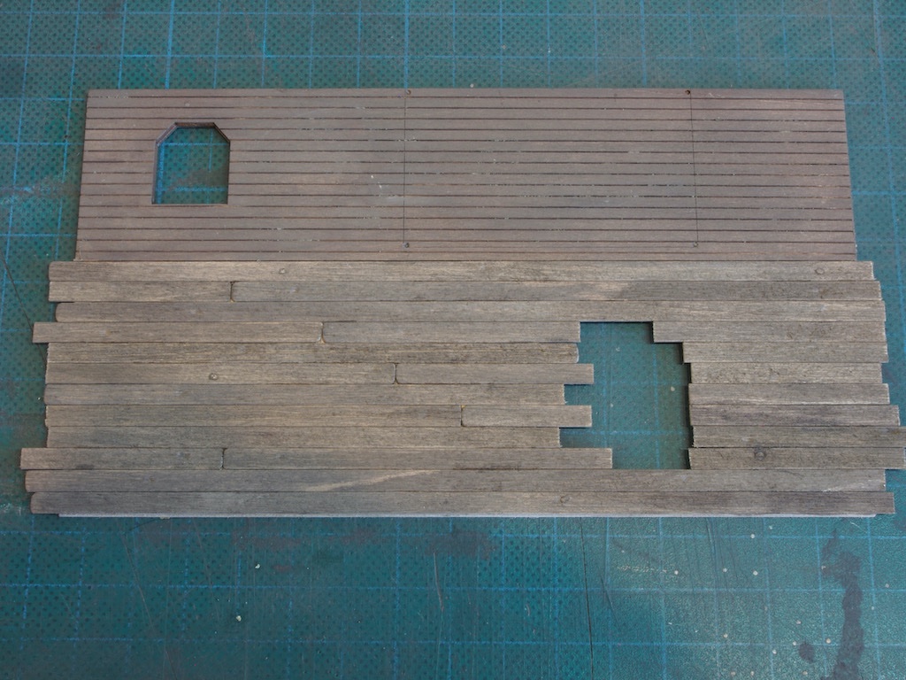
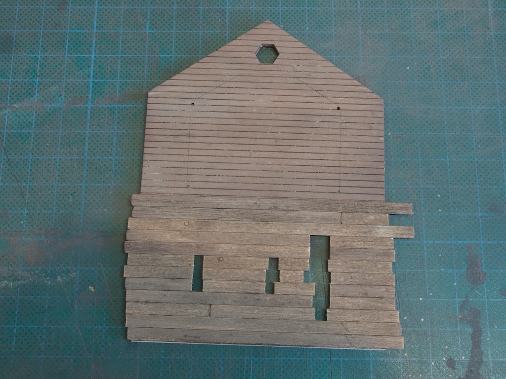
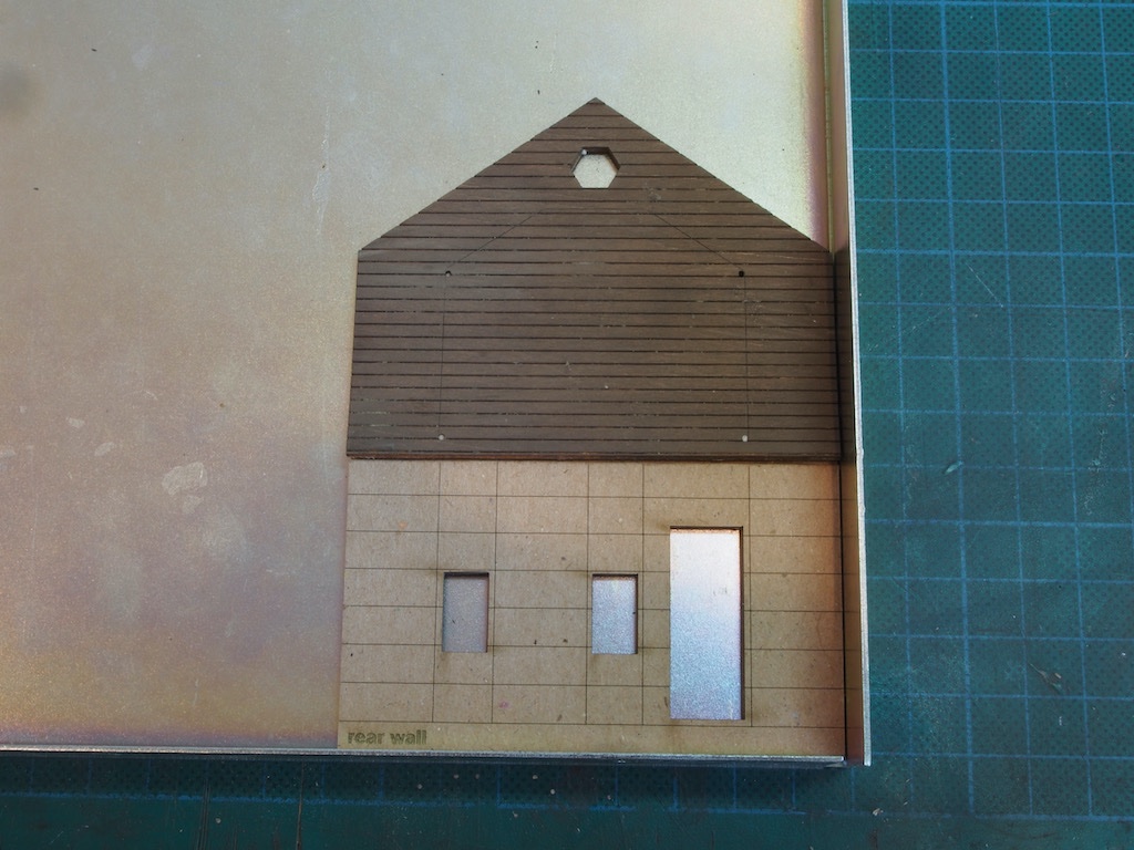
The vertical boards were then added to the second floor in a similar fashion, being careful to align the bottom edges just slightly overhanging the first-floor horizontal boards. I worked in from each side, covering over window openings as I went and then trimming them out once the glue had cured overnight. Here is that same wall after the “repair” treatment and addition of the second-floor siding. The unplanked area is where the dormers will go later on.
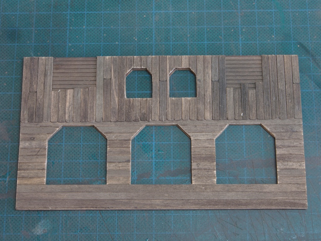
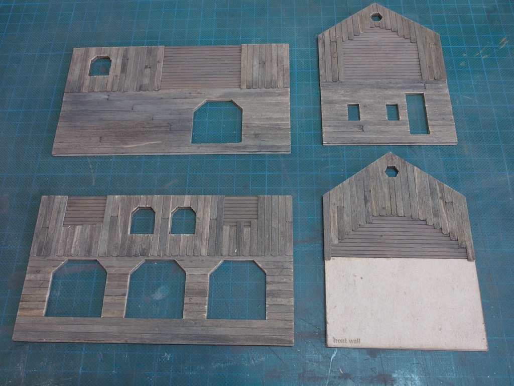
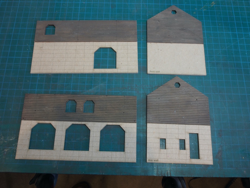
And the remaining walls.
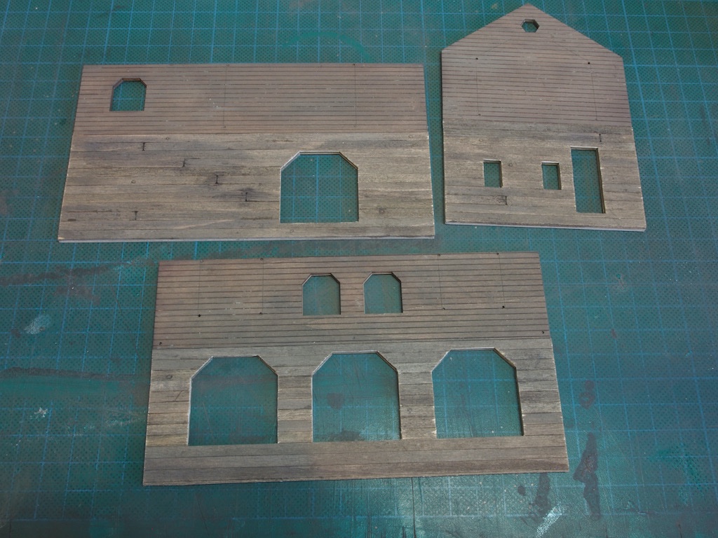
And a “group” shot of the completed walls.
Next up will be to complete the Dormers in a similar fashion and then assemble the laser cut doors and windows.
-
Well, after your success in the prizes at the CMSS this weekend Peter, I’m expecting a top notch build from you. I’m certainly in for following along. Looks like you’re off to a great start.
-
-
-
Thanks for all the likes folks.
Ken - give this method a try before you go down the commercial supplies route. You’ll be surprised at just how easy this method is (and quick).
- Canute, Keith Black, mtaylor and 4 others
-
7
-
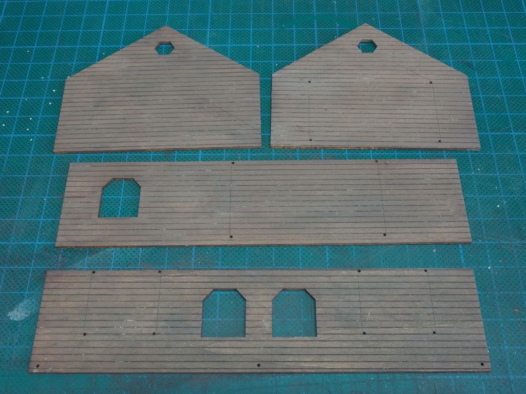
Wall Construction and Board Detailing
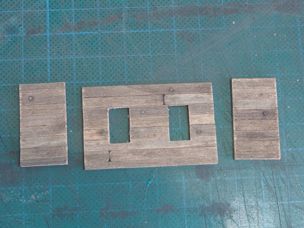
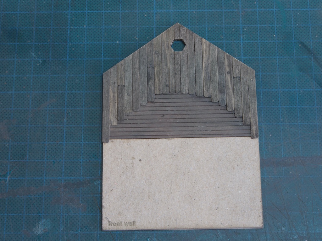
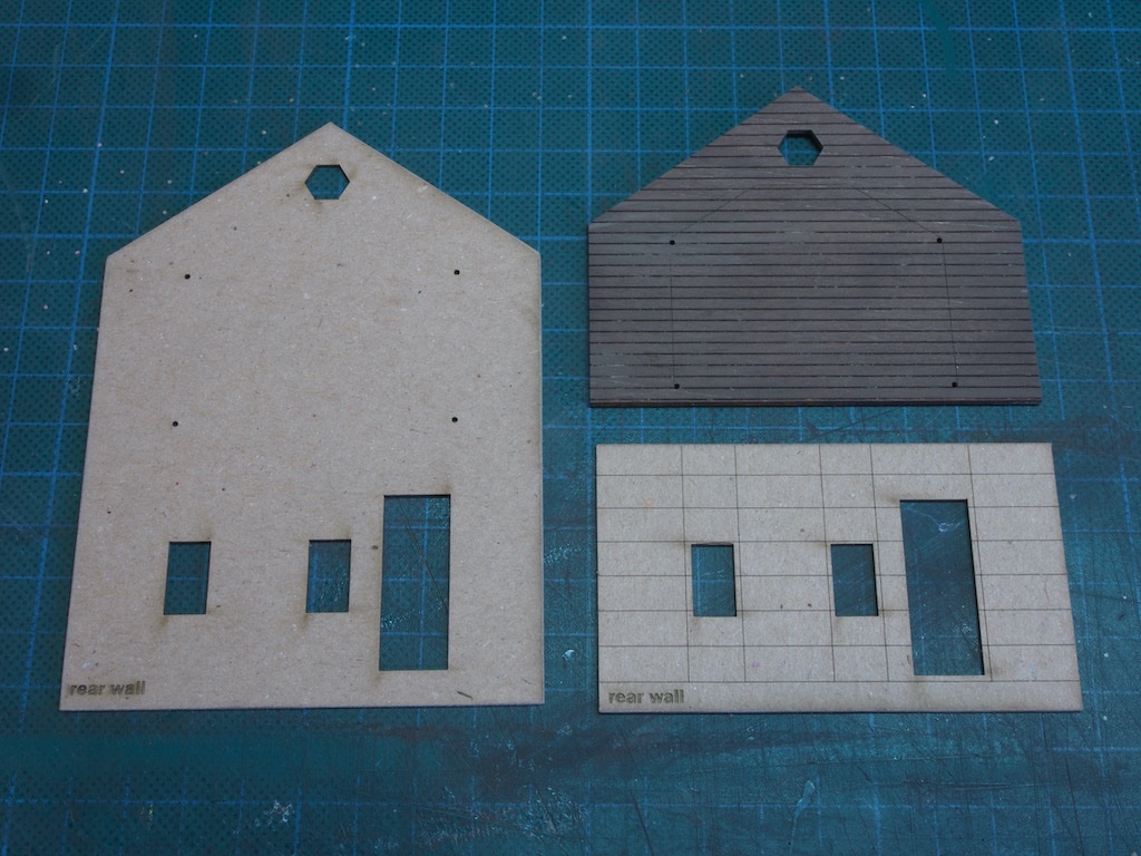
The walls are constructed in three layers. The first layer is a thick card sub-base. The second layer comprises a first (ground) floor card piece and the second-floor scribed siding prepared as in the previous post. The third layer, to be added a little later, is made up from the weathered boards. Here are all three sections for the first two layers.
These are glued up in stages. I used the base of a magnetic gluing jig to help with alignment of the sub-base and first floor piece.
Once that was sufficiently dry, I added the second-floor scribed siding.
Then repeated for the other three walls.
These were then all sandwiched between two glass plates and weighted down with a variety of heavy modelling reference books and left to dry for 24 hours or so to ensure they stayed flat.
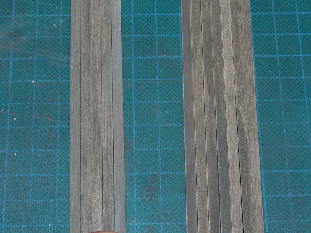
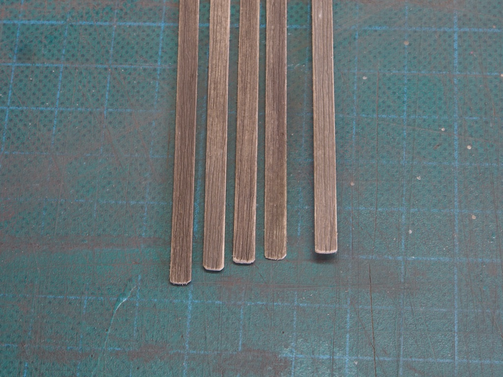
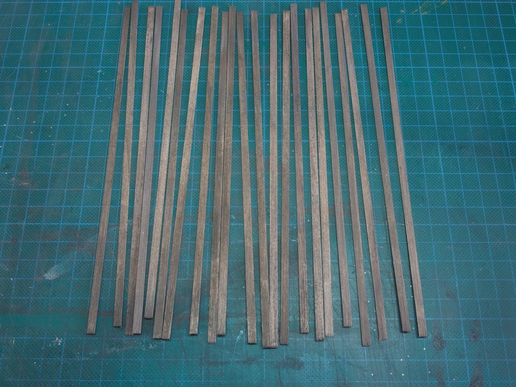
Then it was time to return to creating individual details on the boards. So far, they been given an initial “graining” and treated with a chalk/alcohol mixture. The next step was to lightly sand the top edges of all the boards. This did a few things – first, it removed any remaining ‘fuzzies’; second, it created a very slight chamfer of the board edges; and third, it created a slight highlight along the board edges. The combined effect is to slightly accentuate the join between adjacent boards. In the picture below I’ve placed together several boards before adding this detail on the left, and several after adding the detail on the right.
Next, I slightly rounded the ends of all board. I tried to make this a little non-uniform – not sure to what extent I achieved that, but the sharp corners are all gone. Here is a sample.
Next up, it was time to add some knots. I followed the instructions here, creating both "indentation" knots (using a burnishing tool), and also some "toothpick" knots. I left about 1/4 of the boards with no knots at all, and about half the remaining boards received only "indentation" knots, and the remainder received a combination of "indentation" and "toothpick" knots. During construction, I'll try to mix these up to achieve a fairly random smattering of all the effects.
Here is a "toothpick" knot under construction. I used a small drill bit in a pin vise to make a small hole first, and then inserted the toothpick. I mixed up the angle that these were inserted also.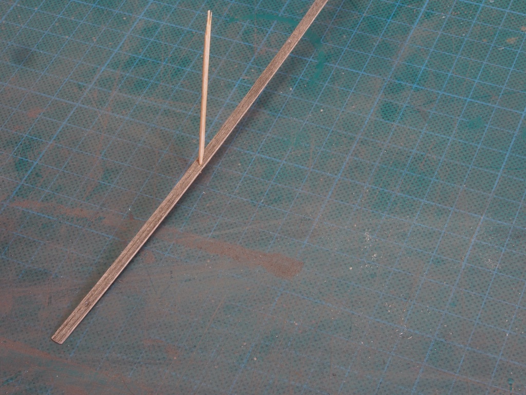
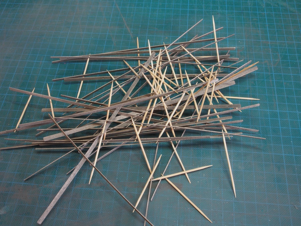
Here's a shot of all the "toothpick" knotted boards awaiting trimming. Some boards got only one toothpick and some received two.
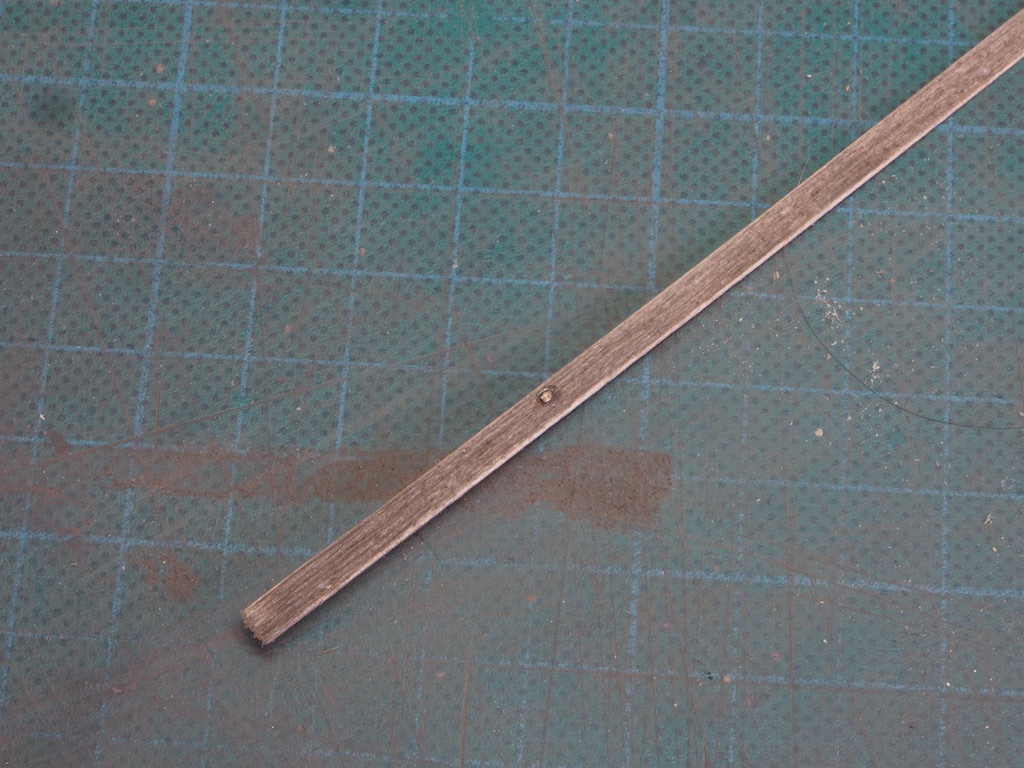
The instructions say to use a pair of straight bladed toe-nail clippers to trim these, adding that these are readily available. Hmmm - maybe on that side of the pond, but down here in the Antipodes, not so easy to find. I did manage to find some online, but had to wait a few days for delivery. Of course, once they arrived, they were the perfect tool for the job. In using them, I made sure that the blades were parallel to the grain direction when in use. Here's one after trimming.
And here's a close up of a few boards showing the overall effect.
At this point, I departed slightly from the instructions. The instructions say to take one board at a time, cut it to size, then brush lightly with a steel brush, dampen with the Alcohol/ink mix, and blot a variety of chalks on with a dry brush while the AI is still damp, then glue the board in place. My variation here was to do all of that except for cutting the plank to size at the beginning and gluing in place at the end. Instead, I did all the remaining tasks to all of the planks, one at a time. It just made more sense to me from a 'process flow' perspective, but I may be missing something here.
I was also a little unsure during this stage. Once again, if you've done this before it's probably second nature, but the first time around, it's difficult to know if you are doing it right. The instructions say "..and make sure not to over apply the chalk". All well and good if you know what the right amount looks like to start with, but doing it for the first time is a little bit of an "adventure". I was concerned that I may have overdone it with the chalk, so I went back and gave the boards another very light pass with a steel brush to remove just a little of the excess, and then wiped my (dry) fingers over the surface. That seems to have done the trick.
Here is a picture of the completed boards with no toothpick knots.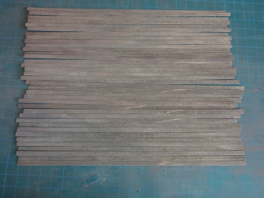
And a close-up of a section of those same boards:
And here is a picture of the completed boards with toothpick knots.
And a close-up of a section of these:
I think I’m happy with these but am awaiting some further critique/guidance from the SW Forum gurus before committing them to glue.
-
Another fine model completed Rusty. Congratulations!👏👏👏
- Rustyj and hollowneck
-
2
-
Wow! doesn’t even begin to describe this Glen - that is just outstanding! Well done Sir! And now we can crack open the champagne…

- mtaylor, Keith Black and Glen McGuire
-
2
-
 1
1
-
Keith is looking very healthy there Glen. A Polar Bear should complete the setting nicely!
- Glen McGuire, Keith Black and mtaylor
-
 3
3
-
Thanks all for the kind comments and likes. To answer a few questions:
Ken - those details will be added to individual planks shortly - that’s the next task.
Popeye - no, there is no intent to add sealer over the chalk stain. The small amount of chalk residue actually helps to create the all-important texture. It’s difficult to describe and even more difficult to photograph, but when you handle the pieces that have been grained and stained, you really get it.
Glen - you have me intrigued… I can’t wait to see what comes out of your workshop next!
Bob - you are too kind sir. 😊
- Keith Black, Glen McGuire, BobG and 7 others
-
10
-
I agree with Lou! Fantastic job Alan - you should be justifiably proud of your achievements with this model.
- mtaylor, Egilman, Old Collingwood and 2 others
-
5
-
Thanks for the kind comments and all the likes. Onwards...
Initial Weathering
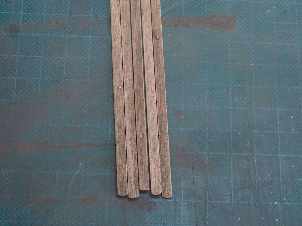
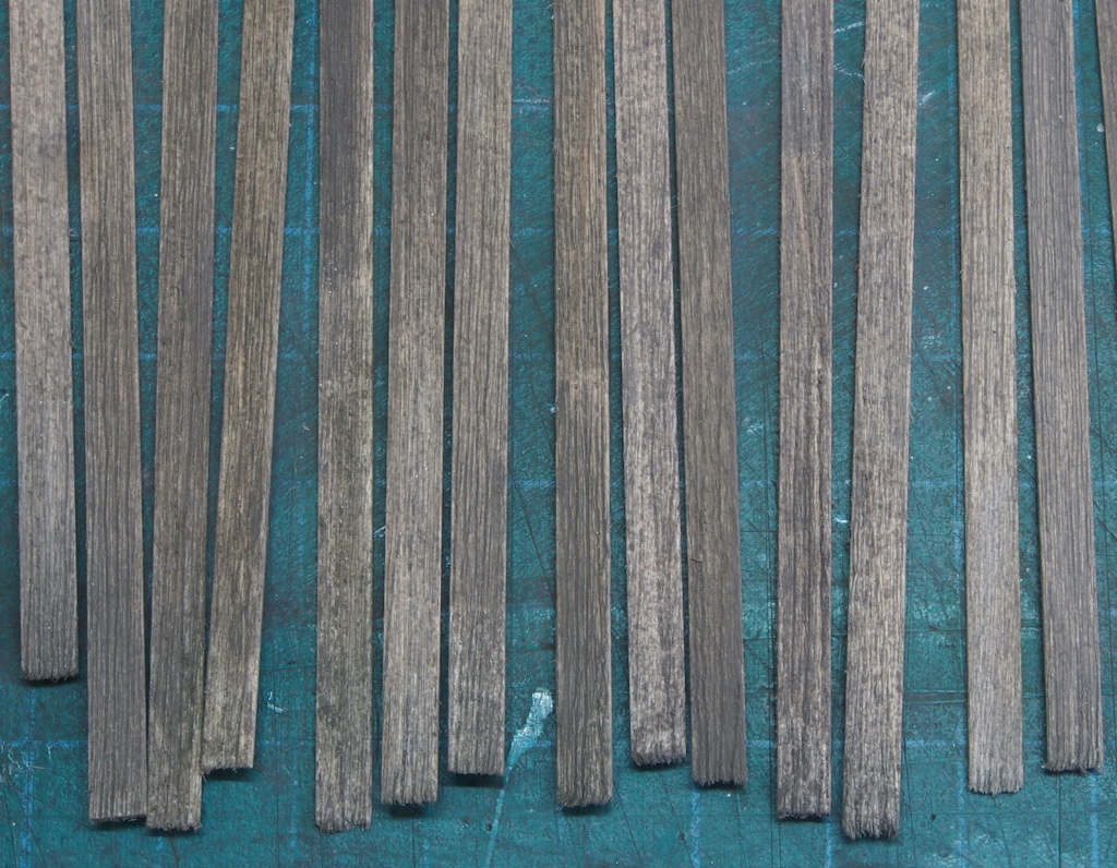
The technique used to create the effect of weathered timber is both interesting and easy, not to mention quick!
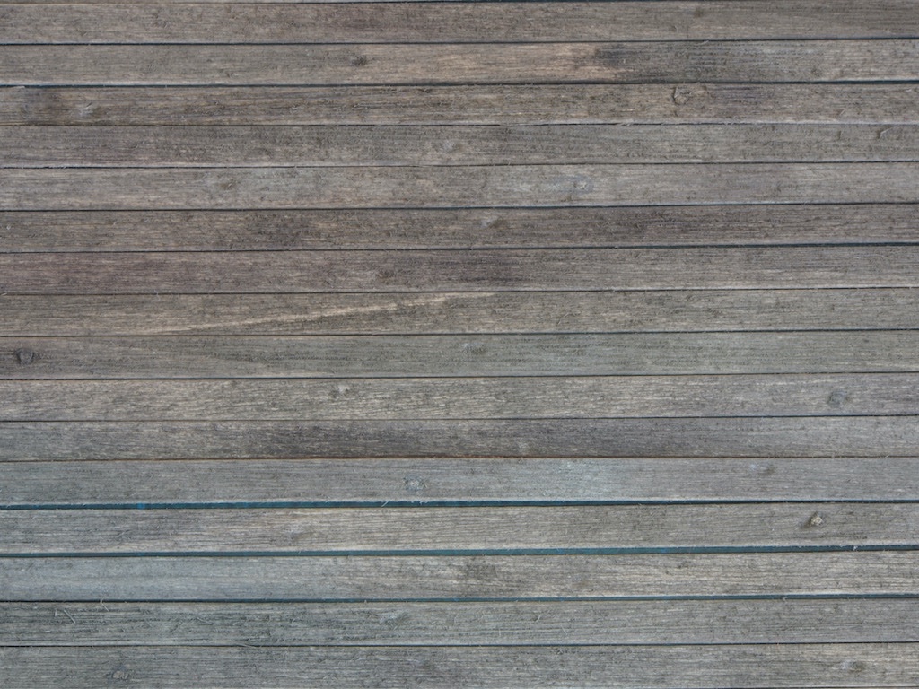
We start by grabbing a half dozen of our previously “grained” boards, a pastel/chalk stick, a single edge razor blade, some isopropyl alcohol (IPA), a paint brush, and a glass work surface (in this case I’m using a piece of glass about 12: square). The technique is to firstly use the razor blade to scrape finely powdered chalk randomly over the boards.
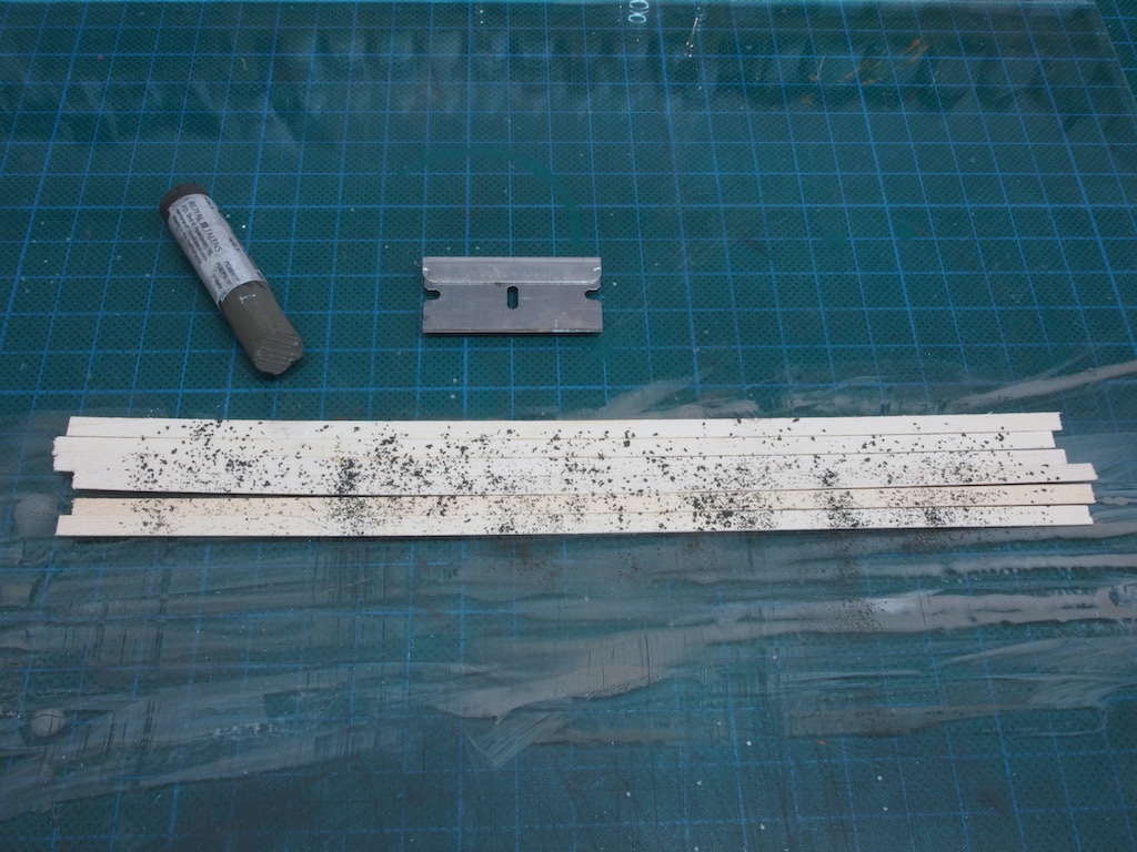
Next, we dip our paintbrush in the IPA and wash the chalk powder into the boards.
The level of colouration is controlled by the relative amounts of chalk and alcohol, the key being to use lots of alcohol to ensure that most of the chalk is dissolved. Further tonal variations can be achieved by using a couple of different shades of chalk. The glass surface is not cleaned between batches, which also helps.
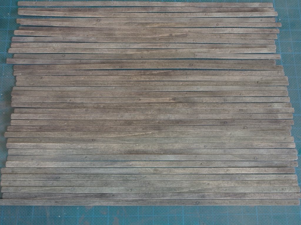
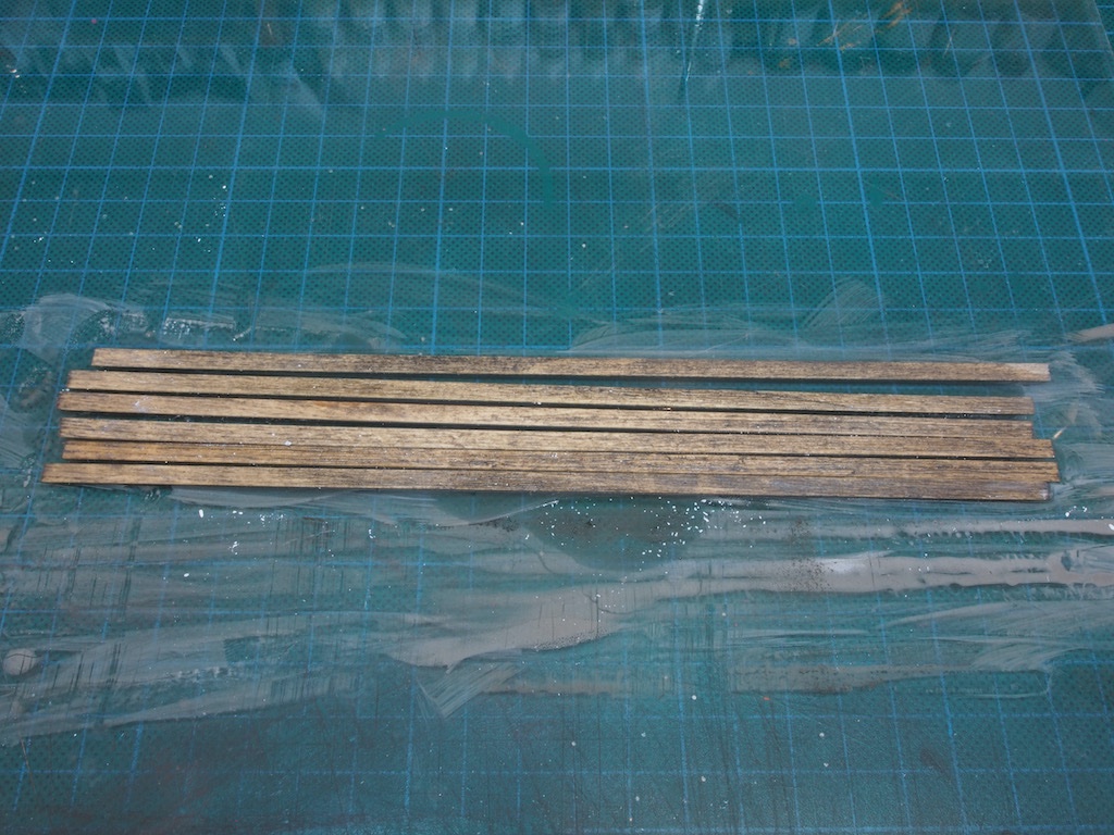
The alcohol evaporates quickly, so the boards dry in next to no time. Here is a random sample from different batches showing the variation in tone.
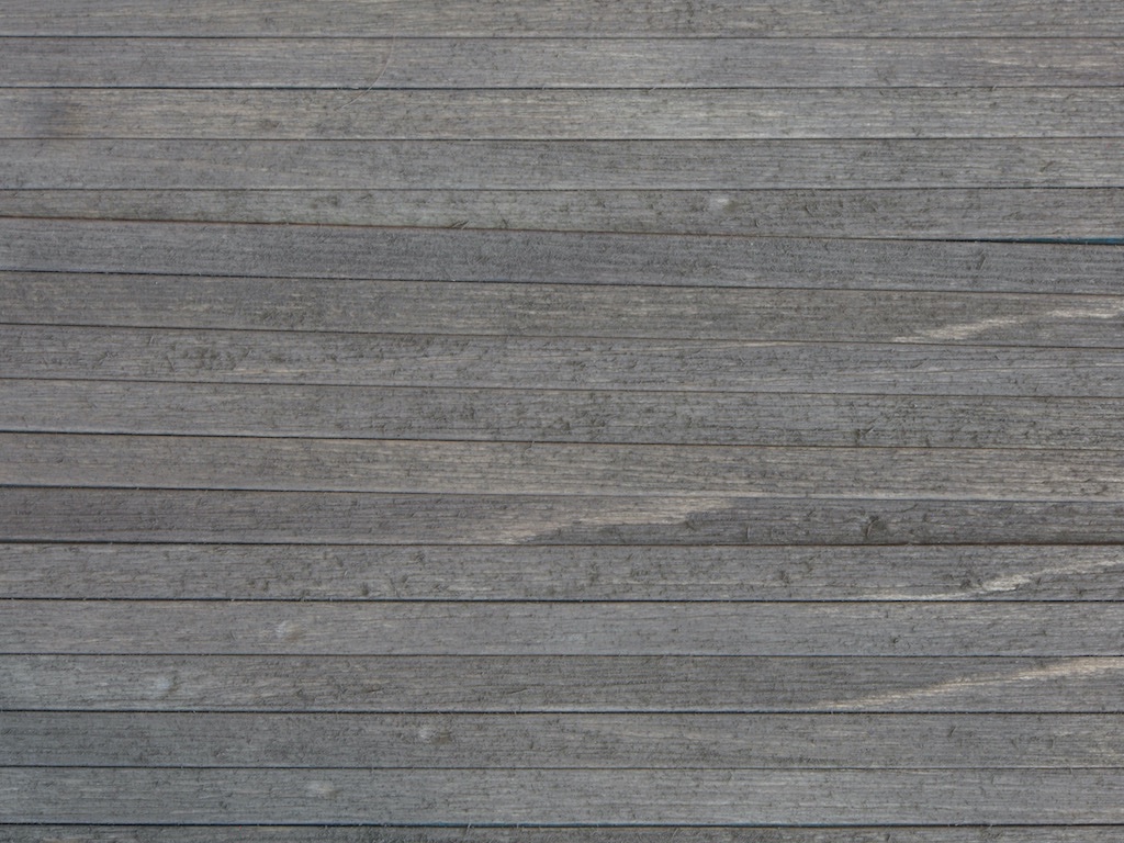
And a close-up of some of the same selection.
I also did some preliminary preparation of some laser-cut siding. These pieces will eventually be covered by the boards just prepared, but they are given an initial colouring so that any gaps in the boards will show this. The key here was to achieve a non-homogenous look. This is done by staining the boards with paint and thinner, and then adding a little chalk blotted into the surface using a paper towel wet with the paint thinner. Here is the result.
The next stage will be to add some details such as knots, knot holes, splits, insect damage etc to some of the boards.
-
Congratulations Glen - that looks fantastic! I’ll hold the champagne until the base is done - if it’s anything like your previous efforts, that will be special too.
- Keith Black, mtaylor and Glen McGuire
-
2
-
1
-
Looks great Alan, although to be a little picky, your Ensign does appear to be flying at half-mast......
- mtaylor, lmagna, Old Collingwood and 2 others
-
5
The Shipyard at Foss' Landing (Diorama) by gjdale (Grant) - FINISHED - SierraWest - Scale 1:87 (HO)
in Non-ship/categorised builds
Posted
Thanks Ken - I suppose you could brace the corners, but it doesn't appear to be necessary with the design of this kit. The floor pieces, and later the roof pieces, will provide all the bracing required.
Wall Construction – More Details
The next step is to add trim to the ends of the remaining Dormer walls, as well as windows, before joining the walls together and adding floors.
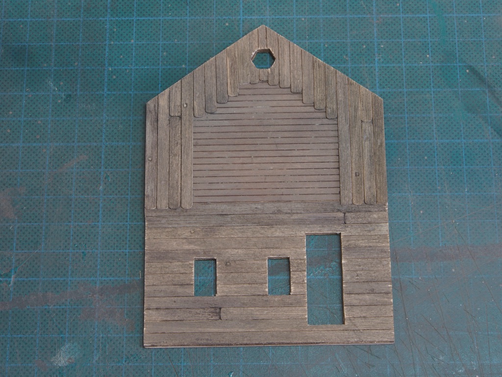
Here are the two Right Wall Dormers completed – these have a rear wall added as well. These macro shots also show the nail hole details quite well.
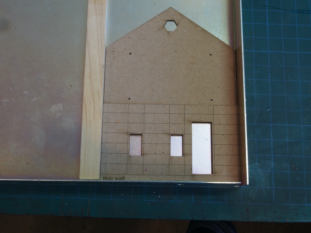
And here is the Rear Wall Dormer.
Our attention then returns to the main walls, starting with adding Hinges and Handles to the previously prepared Freight Doors.
The previously prepared Main windows and their frames are then attached to the walls. To insert the Freight Doors, a template piece is provided that inserts in the openings and enables the Freight Doors to be recessed just the right amount. Once the doors are glued in place, the frames are added on the outside.
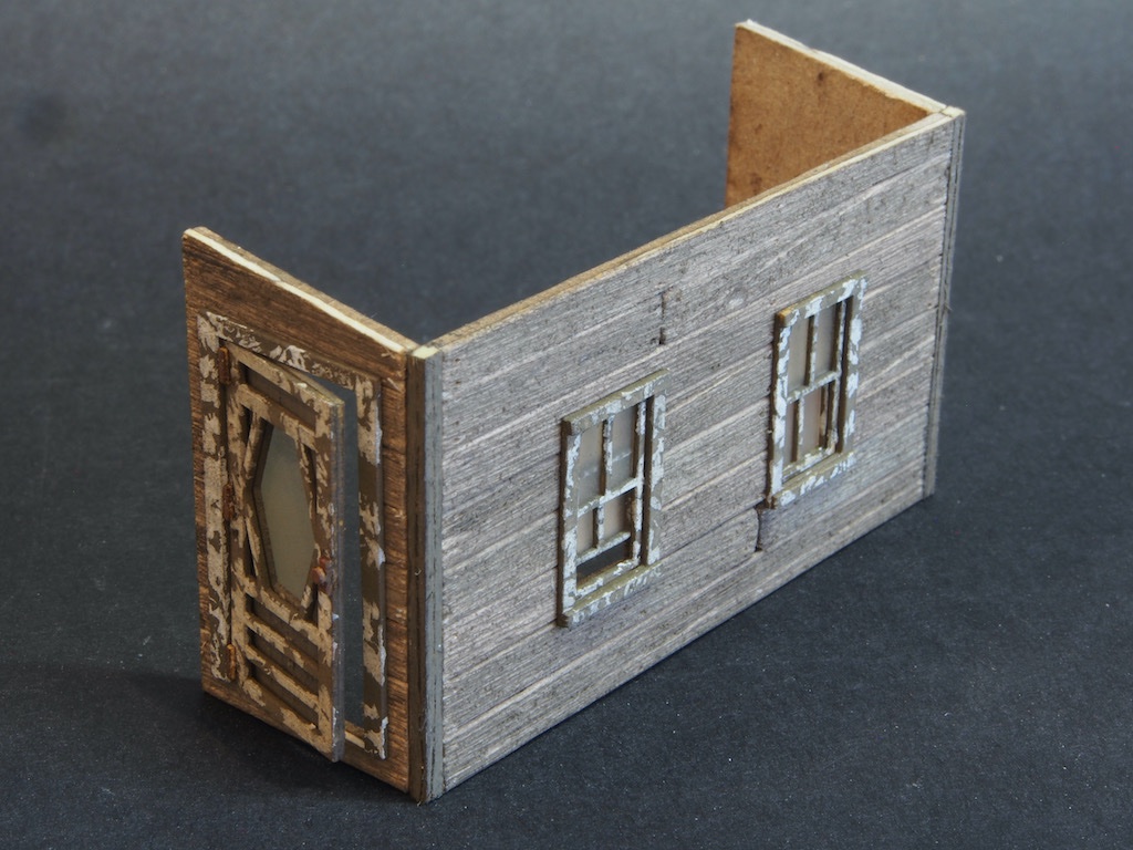
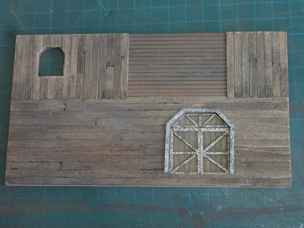
Here is the Right Main Wall, with the three freight doors and windows installed.
And here is the Left Main Wall. On this wall, I opted to leave the Freight Door slightly ajar for added interest.
The End Walls are next….