


gjdale
-
Posts
4,819 -
Joined
-
Last visited
Content Type
Profiles
Forums
Gallery
Events
Everything posted by gjdale
-
 As others have said Rick, a fine model of which you can be justifiably proud. Congratulations and well done! I’m sure you will enjoy similar success with your Cheerful build.
- 155 replies
-
- 2
-

-
- Medway Longboat
- Syren Ship Model Company
- (and 1 more)
-
Mark, A digital microscope with a 7” LED screen can be found on Amazon or eBay for not very much at all - in the range that JD mentions or perhaps even less. I’ve recently acquired one myself, but have not done any carving. I’m sure it will have all sorts of uses for our hobby.
-
Always a joy to watch you work your magic BE. I’m taking a front row seat for this one.
- 639 replies
-
- 5
-
-
- Indefatigable
- Vanguard Models
- (and 1 more)
-
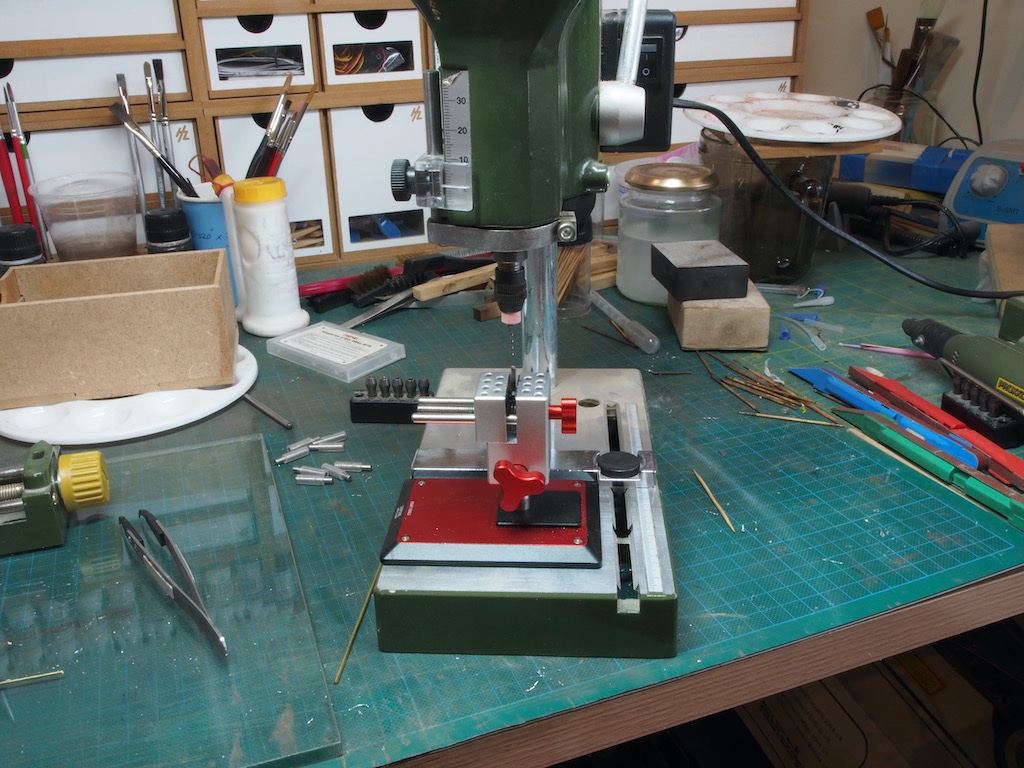
Thanks very much Glen, Gary and Bob - the boo-boo was one of those Homer Simpson moments (Doh!). Just a really stupid, avoidable mistake. You may not notice it, but it will forever be the first thing I notice when I look at it! That’s just the way we are as modellers. DSPIAE is the brand name Bob - I don’t know if it is also an acronym. My drill press is a Proxxon TBM 220. I’ve had this for quite some time now and have found it very useful for general purpose work and it lives on my modelling desk always at hand. I also have the fall back of the Sherline Mill with sensitive drilling attachment for even more precise work when needed. 😊 I think I am well placed in the competition for “he who dies with the most tools wins”………….😉 I just hope that when I do fall off the perch, my wife doesn’t sell my tools for what I told her I paid for them………
-
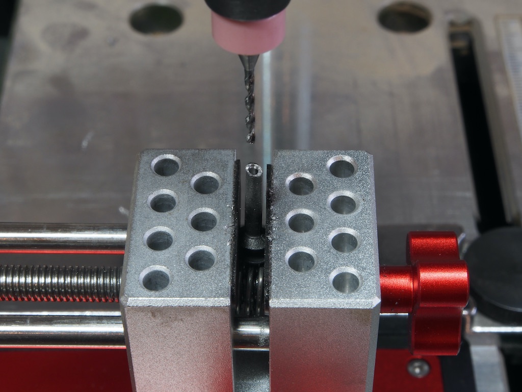
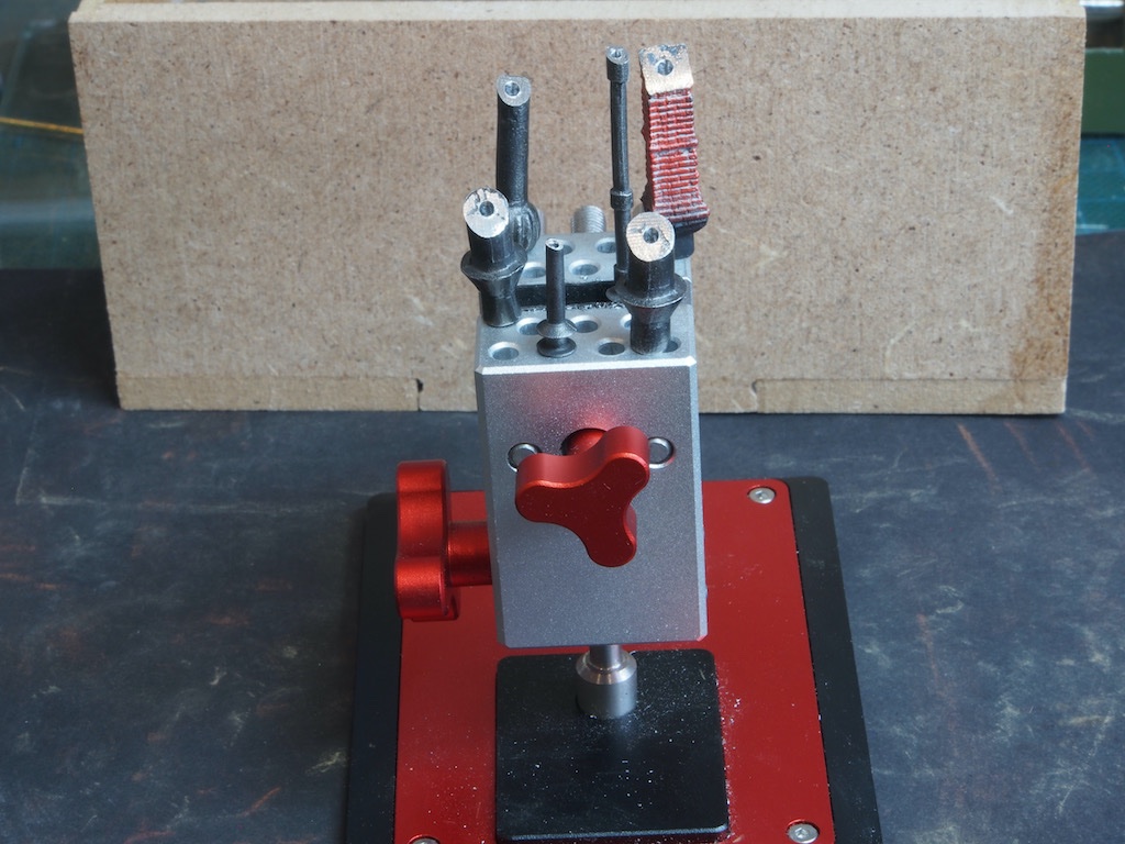
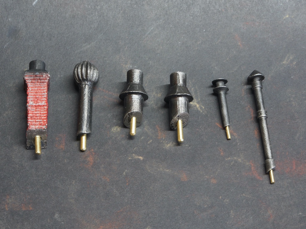
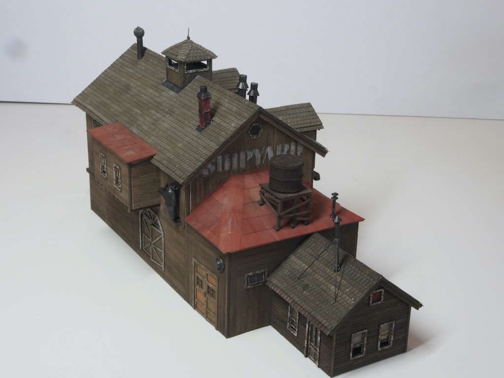
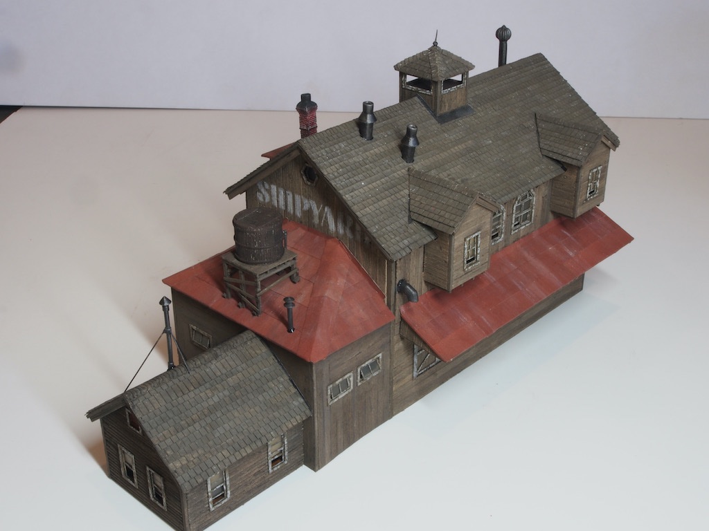
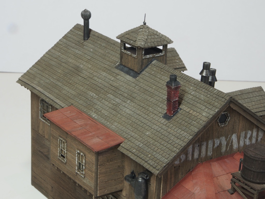
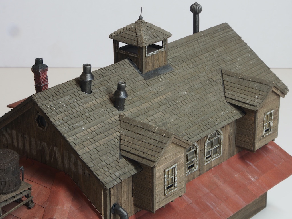
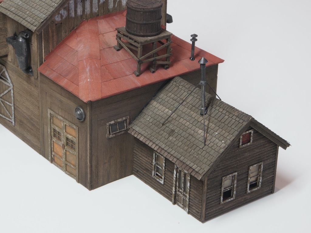
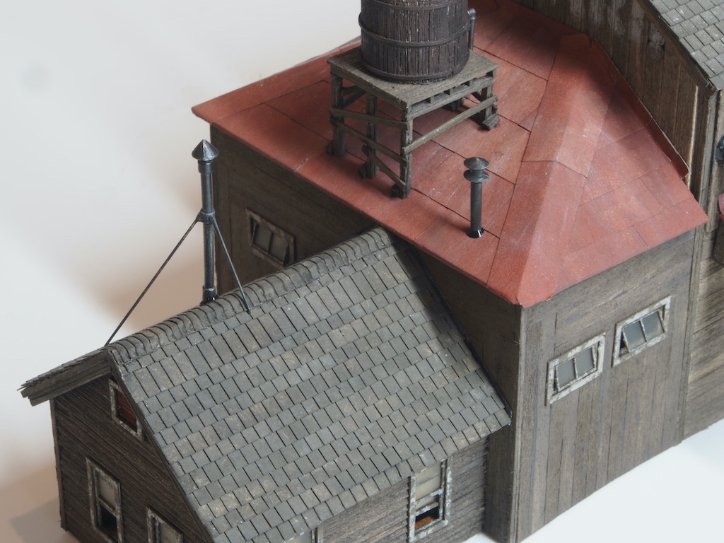
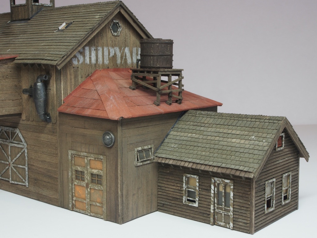
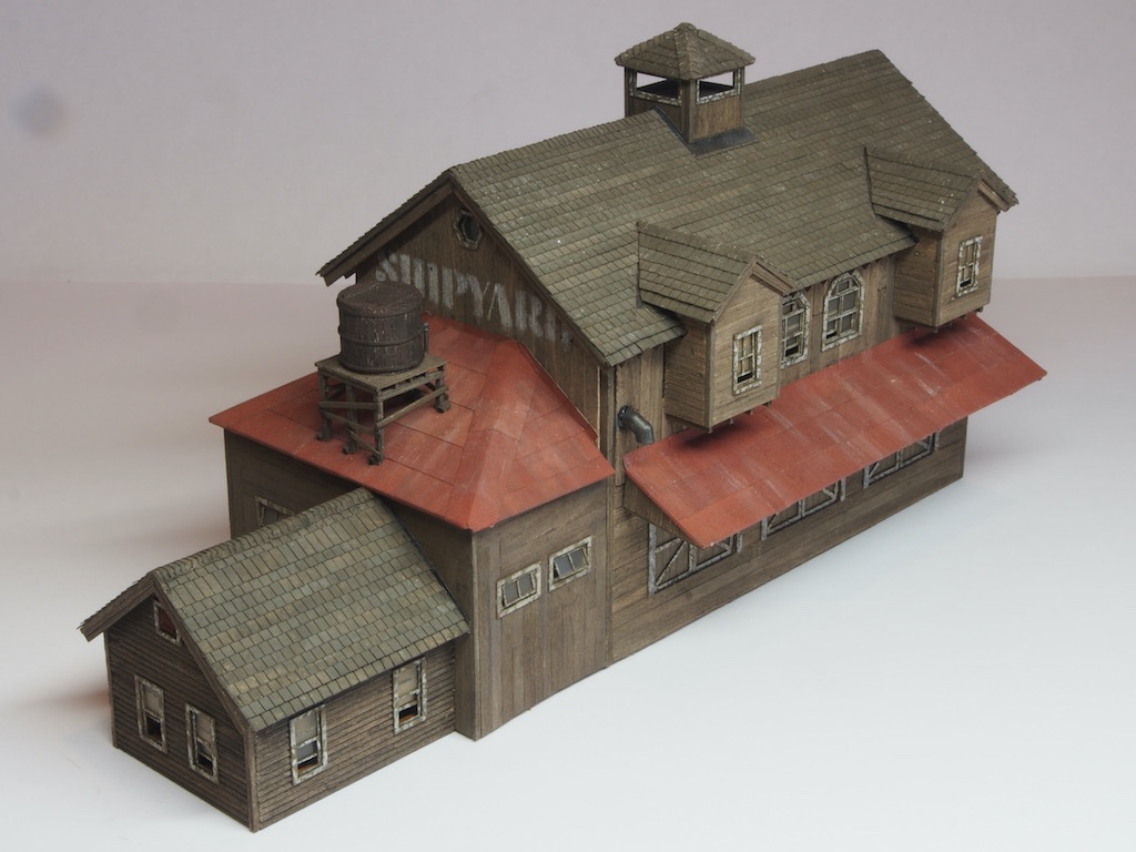
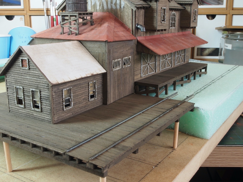
Thank you very much OC, and to all of the likes. With the roofs now complete, I was able to turn my mind to the roof hardware installation. My concern here was that as these parts were nearly all made from white metal (except the chimney, which is resin) and they all had angled bases to sit against the roof, they would be difficult to hold in place while the glue dried. I decided to add a small spigot to the inboard end of each piece, to be inserted into a corresponding hole to be drilled into the roof. My hope was that the spigot would provide the necessary stability while the epoxy set. For the four larger diameter pieces, a 1/16” (1.6mm) brass rod could be used for the spigot, however for the two smaller diameter pieces, only a 1mm diameter piece could be used. Drilling these holes into the angled bases without the drill bit deflecting or breaking was the key challenge here. Once again, my little DSPIAE vice proved its worth, holding the piece securely under the drill press. Here is one of those smaller pieces being drilled with a 1.1mm bit. (This is the tidy side of my work space!) And a little closer shot. And here are all the pieces drilled and ready to receive their spigots. A short section of brass rod was then epoxied into each of the pieces and locating holes carefully drilled into the roof using a pin vice. The individual pieces were then epoxied in place and the spigots did their job of holding things securely while the glue cured. Once the glue had cured, the stack on the Yard Master’s Office had three supporting wires attached. These were made from 0.5mm diameter brass rod, cut to length, blackened, and then epoxied into place. To assist in positioning these, a small “elbow” was bent into the bottom end of each and inserted into a corresponding locating hole drilled into the roof. Here are a few overall shots of the roof hardware in place. At some point I managed to knock off the top of the lightning rod on the top of the cupola, but managed to glue it back in place with some CA gel – still looks a bit wonky in these pics – may have to try and straighten later. And here is the Yard Master’s Office Roof: In the above photos, you can see the boo-boo I made when shingling the Yard Master’s Office roof. I only spotted this when I was installing the roof hardware. I knew that I had to use a thinner shingle strip for the final row, but I forgot that I should have still used a normal width row first, and then placed the thinner row on top. The result is an elongated row of shingles (second row below the capping). I briefly considered whether this might be salvageable, but in the end decided that it was too high a risk of doing extensive damage. I will just have to live with this one. Looking at the close-up photos, it looks like I need to go back and dull down some of the "pitch" at the base of some of the hardware items too. With the roofs finally complete, I can now return to the ship under construction.
- 326 replies
-
- 15
-
-

-
The header does seem to have the wrong scale there, but if you look below at all the build log titles, nearly all of them include the scale in the title - either 1:24 or 1/2” (same thing). And Chuck (the kit designer and manufacturer) has given you the definitive answer as well.
-
I’m pulling up a chair for this one too, Kevin. Off to a great start.
-
Great start Mike. I look forward to following along.
-
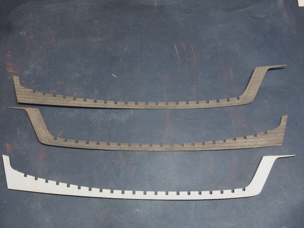
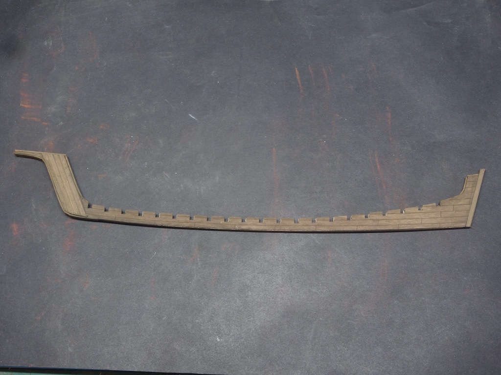
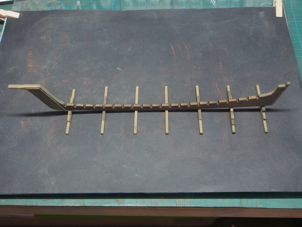
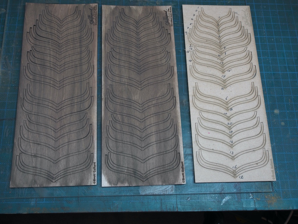
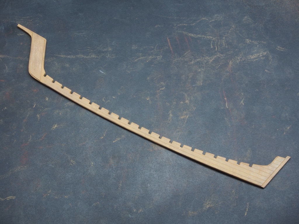
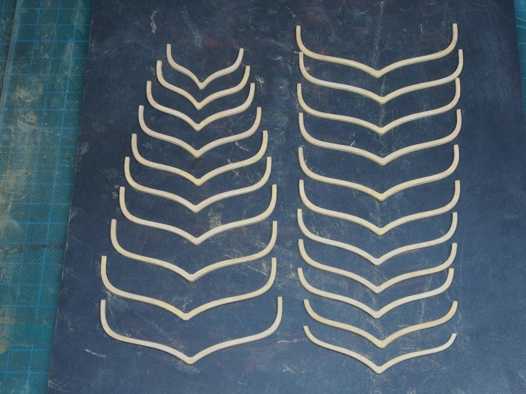
Thanks again everyone for the kind comments and all the likes. It's been an "interesting" week or so.... The Ship Under Construction The ship under construction is an important element in the diorama – after all, it is the reason for the existence of the Shipyard! We begin with the Keel, which is provided in the form of three laser cut pieces – one cardboard central piece, and two outer veneers that include some laser scribing. The outer pieces are first given a light wash with AK 11110 (Leather Brown) – my substitute for Floquil Roof Brown – and then stained with chalk and alcohol. The three pieces are then glued together, and some trim pieces added at stern and stem. The keel supports are now added, building them up as needed to keep the keel relatively level. The frames (or “ribs” as the instruction manual calls them) are made up of a three part lamination in the same way as the keel. Again, the outer pieces are stained prior to gluing up. The central pieces have a laser engraved number on them, but as this disappears once glued up, I took the sensible precaution of numbering the carrier sheet to ensure later positive identification. We then start adding the frames to the keel notches. I had placed four of these when I had the thought that perhaps the ship would look better if the timber looked more like freshly cut wood, rather than the same weathered look of the buildings. While I was thinking on this, I had a PM from one of the people following my build suggesting exactly that and pointing me to a thread where he had done exactly that. So, there was nothing for it but to deconstruct the frames and keel supports and re-visit the colouration, starting with giving all the pieces a light sanding. Following the example given in the discussion thread, the next step was to apply a base coat of AK11004 (Ivory) – my substitute for FLoquil Aged (Antique) White. After a little trial and error, I then settled on a combination of Rembrandt 231.3 (Golden Ochre) and 234.3 (Raw Sienna) chalks. Once the alcohol/chalk treatment had dried, I went over all the pieces lightly with a steel bristle brush. This removed the excess chalk and ensured that any scratch lines followed what would be the line of the grain. Here is the keel ready to go. And here are the frames also ready to go. During the week, my additional shingles arrived in the post (at last), so I was able to go back and complete the roof on the Yard Master’s Office. This included finishing the shingle laying, capping the roof, adding rafters and rafter tails, and adding the flashing at the rear of the roof where it will adjoin the Warehouse. I didn’t take any in-progress shots of these steps as these are simply repeats of earlier work. I was then able to join the Yard Master’s Office to the Warehouse/Main Building. I also decided to switch my photo background from black to white for these shots. After taking these pictures, I realised that the rafters on the end of the Yard Master’s Office are not quite in the right position, so I may have to some delicate deconstruction/reconstruction tomorrow. I also now need to add the roof hardware (chimneys etc), which will be a challenge in its own right!
- 326 replies
-
- 21
-
-
-
Just a thought Glen, but you could try some "googly eyes" (readily available on Amazon/ebay) - though they might not pass the "too ridiculous" test........
-
I rather thought you might have taken ill with PROVID 22 ( "Procrastination Virus variant 2022") Bob - it happens to all of us. You are quite right about getting going again. Choose something, anything, as long it gets your juices flowing - and start building. I really enjoy following your build logs and miss not having one active to peek over your shoulder with.
-
The yard foreman just called Bob. He wants to know when you’re coming back to work!
-
It's a general purpose ship under construction - just keel and ribs and lots of scaffolding.
-
Nice to see you back at the bench Mark. Your Sphinx is looking great.
- 505 replies
-
- 11
-
-
- vanguard models
- Sphinx
- (and 1 more)
-
Thanks Glen. Actually, the hard part was figuring out the methodology. Once I'd designed and tested the jig and the methodology, the rest was pretty easy.
-
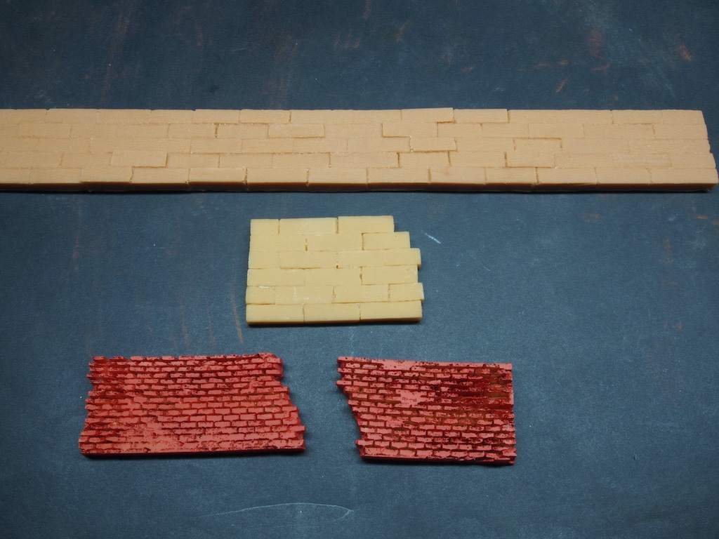
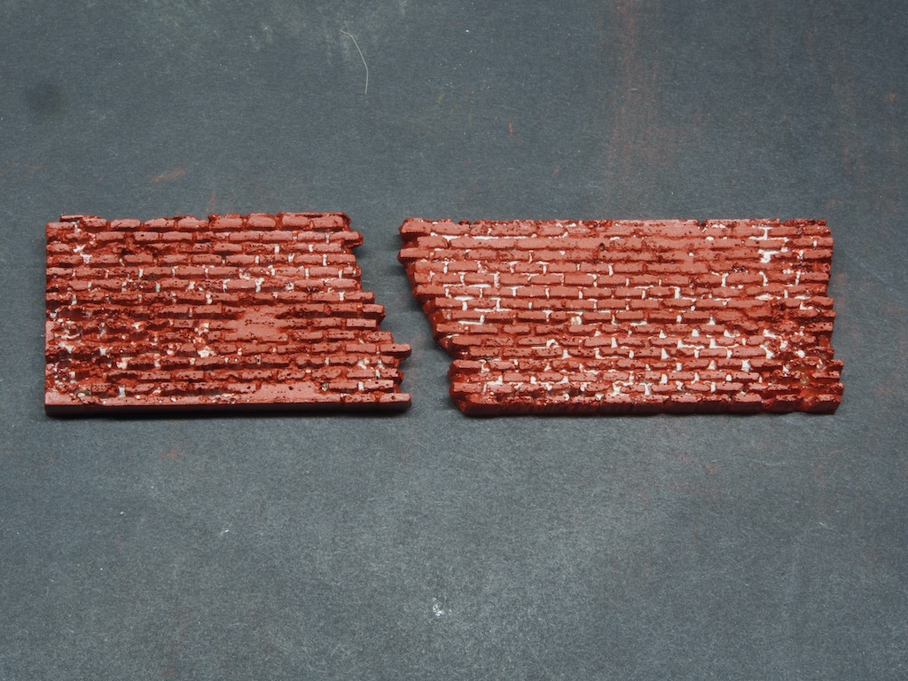
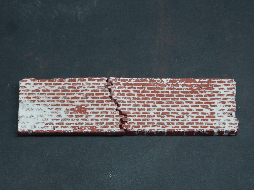
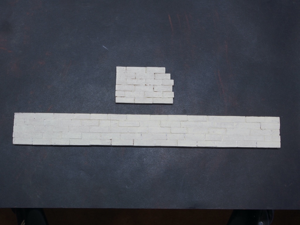
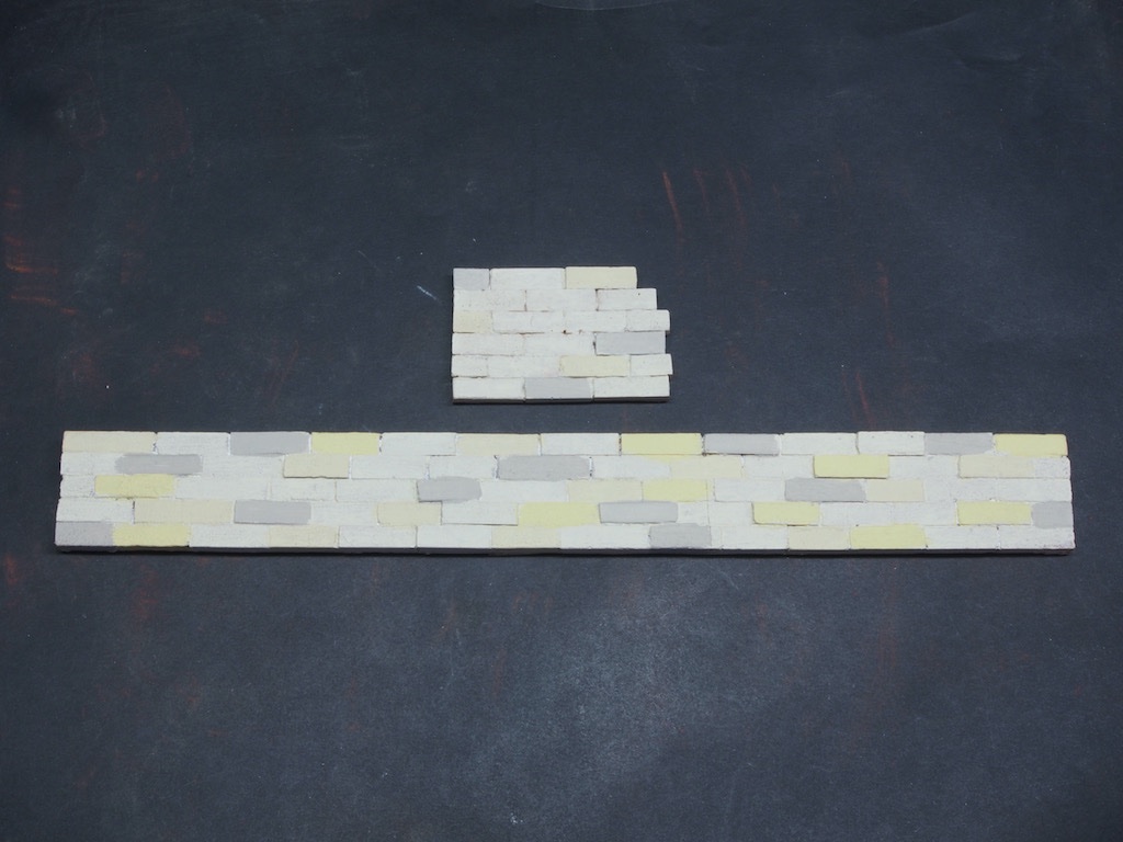
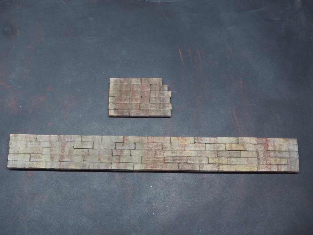
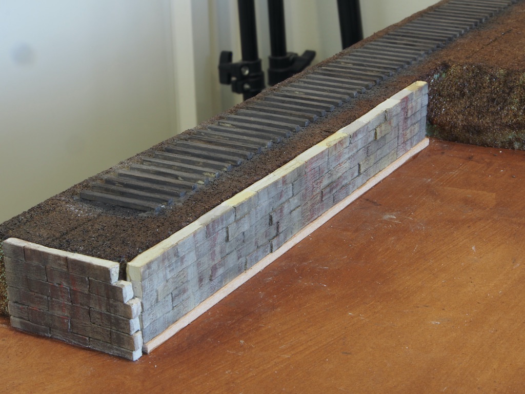
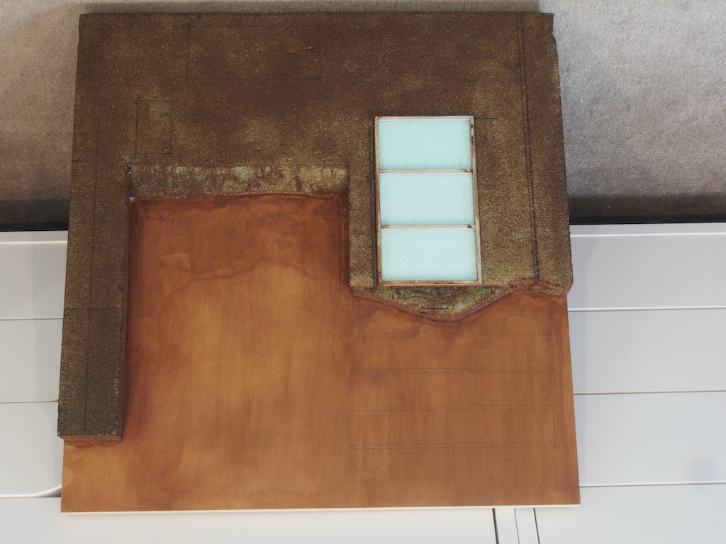
Continued from previous post... We are then instructed to complete the preparation of the brick retaining wall and the sea wall, both resin castings. The brick retaining wall comes in two pieces that fit together like a jig-saw puzzle and is designed this way to show the deterioration of the wall. In the picture below, the brick wall has been painted its base colour, while the sea wall (also two pieces) are shown in their unpainted state. The process for the brick wall is to paint the casting, then cover the entire casting in plaster, washing off the surface to leave the plaster in the joints. I had some trouble with this as when I washed the plaster of the surface, it also took the paint off. I had done this using acrylic paint (AK paints). After a second failure, I spent some considerable time cleaning as much of the plaster out of the joints as I could before starting again with a lacquer-based paint. Here are the wall pieces after cleaning out. And after application of a red-oxide lacquer primer and re-treatment with the plaster. The sea wall gets an initial undercoat of AK 11008 (Grimy Grey). A random application of three other colours is then applied AK 11031 (Buff), AK 11007 (Rock Grey) and AK 11057 (Vampiric Flesh). A light wash of alcohol and chalk powders is then applied (I used both 408.3 (Raw Umber) and 411.3 (Burnt Sienna)) for this. These washes produce quite a transformation… The walls are then test fitted and a strip of scrap wood used to block them up to just below the surface of the diorama before epoxying into place. We now leave the diorama base for the time being and commence construction of the star of the show – the ship!
- 326 replies
-
- 17
-
-
-
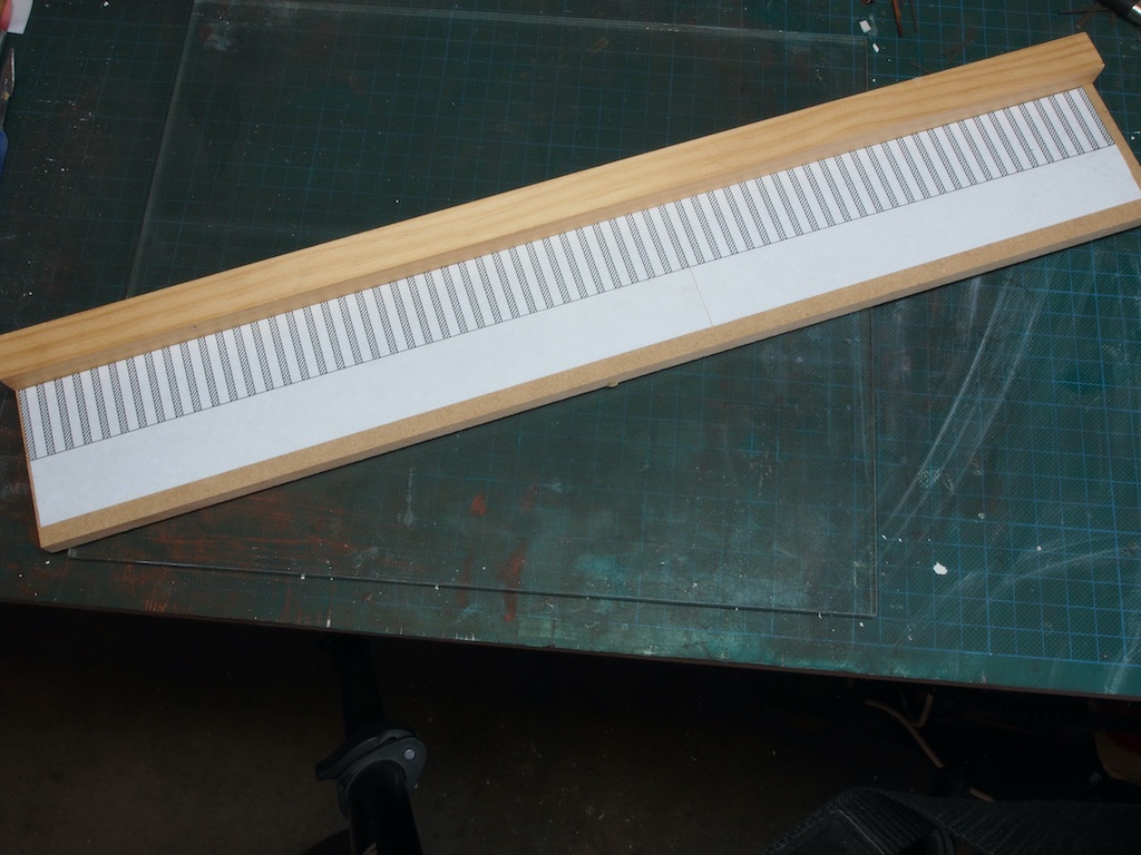
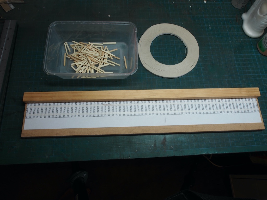
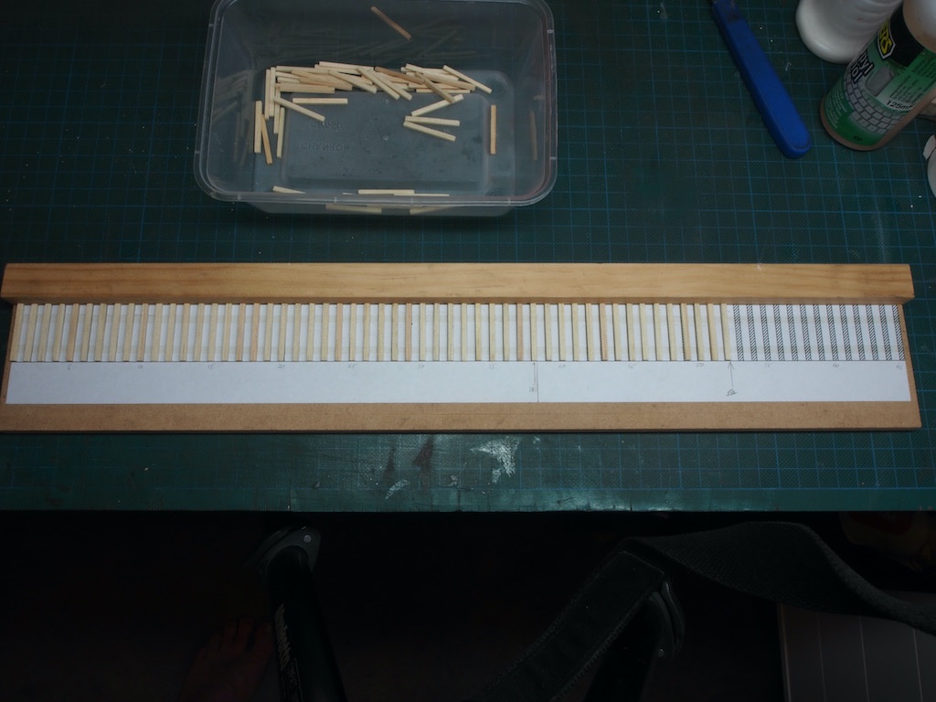
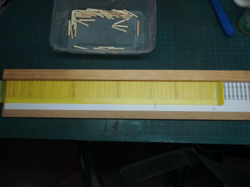
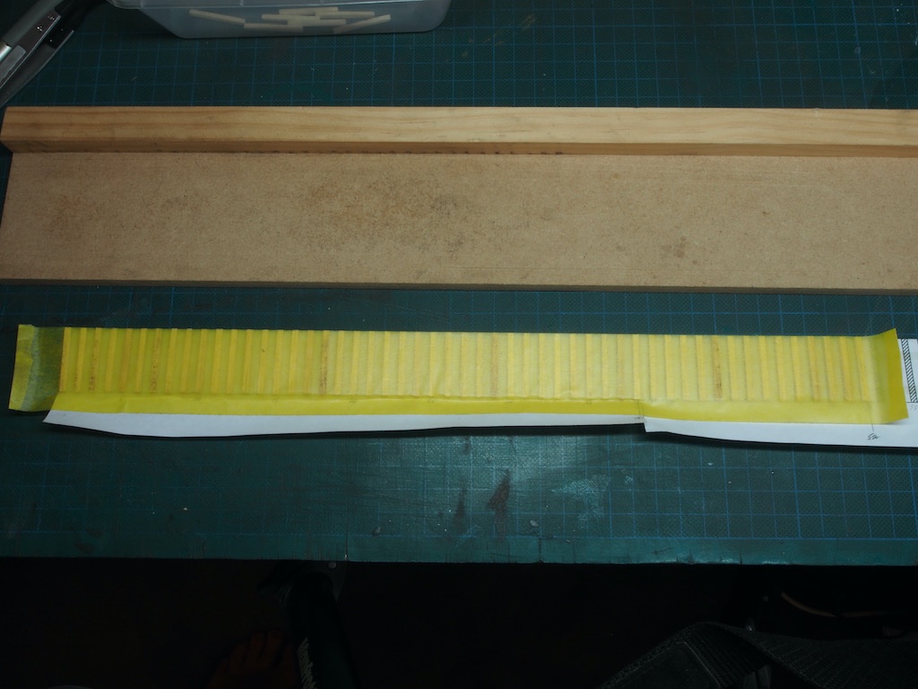
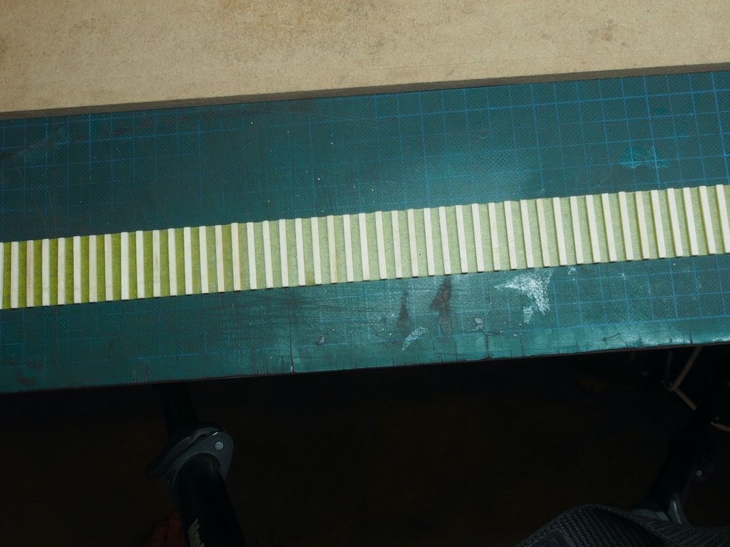
Continued from previous post... We are then instructed to test the fit of the ties we will be using, ensuring they fit flush under the rails extending from the dock, and then to epoxy these down. The ties are not included with the kit, presumably because there is an assumption that anyone building this kit is a model railroader and will have their own supply of these. A quick search on the internet and I was able to locate and procure some HO scale ties (Mount Albert brand). I could have made these from scratch material, but this was a quick and convenient solution. The bigger problem was how to space them correctly, and before that, working out what the correct spacing between ties should be. A search on the internet revealed that there are three common spacings between centres used (assumed “standard” gauge and not “narrow” gauge) – 20” for “main” line, 22” for “branch” line, and 24” for “sidings”. Lacking any further guidance, I decided that the lines in this diorama would be considered “sidings”, so went with 24” between centres. I then drew up a paper template using TurboCAD and attached this to simple jig using temporary spray adhesive. The jig is simply a scrap piece of 9mm MDF with another piece of scrap wood as a straight edge to but the ends of the ties against. Two pieces of very narrow double-sided tape are then laid on top of the template to hold the ties in place. And the ties are added – in the example below, the is the longer of the two tracks that will run alongside the derrick dock on the left of the diorama. The ties have all been “grained” and cleaned of fuzz. I initially tried staining them first, but quickly discovered that they would not stick well to the double sided tape, nor the masking tape in the next step. A piece of high tack masking tape was then laid over the ties and pressed firmly into place. The entire template assembly was then removed from the jig by carefully peeling away the template paper from the jig (hence the use of temporary spray adhesive earlier on). The excess tape and template paper were then trimmed from the edge, and the remaining template paper carefully removed along with the double-sided tape, leaving the ties attached only to the masking tape and ready for placement. Having marked the position of the tracks onto the diorama base, a layer of epoxy was applied to the base and the ties placed in position. I used a 15 min epoxy for this task just to allow myself a little extra time to make sure everything was in the right place. Once the epoxy had cured, the masking tape was removed, et voila! The ties were given the alcohol and chalk powder treatment. For these I was going for a much more greyish tint to the colouring than used on the main buildings. Continued next post...
- 326 replies
-
- 13
-
-
-
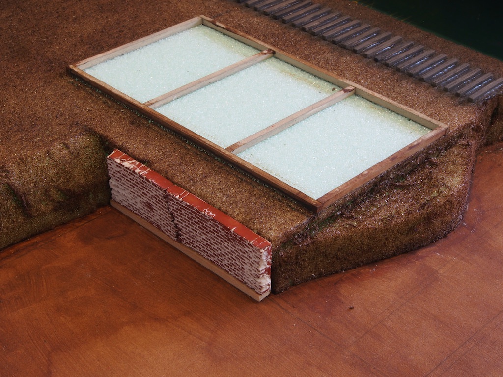
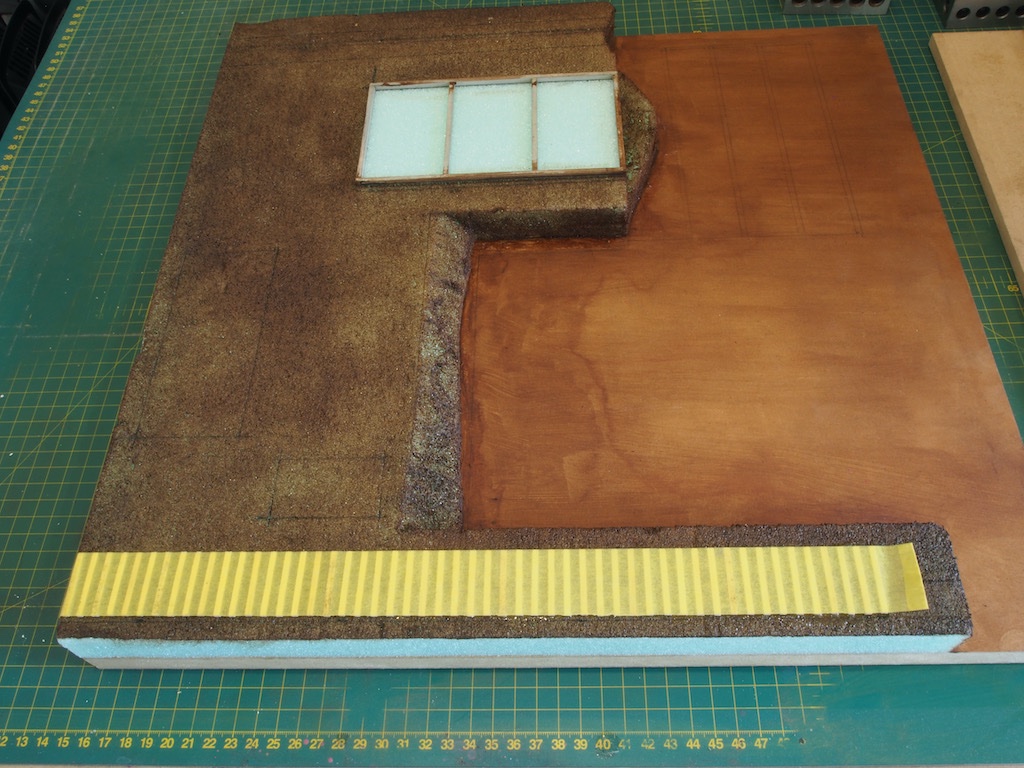
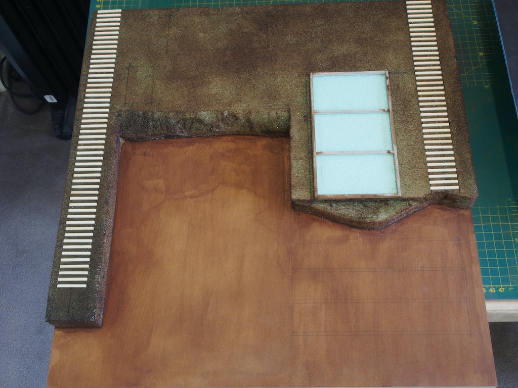
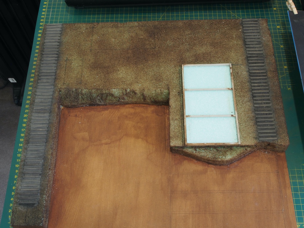
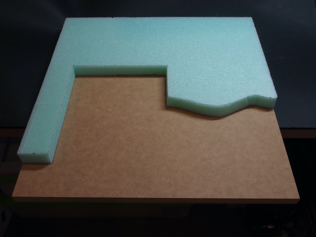
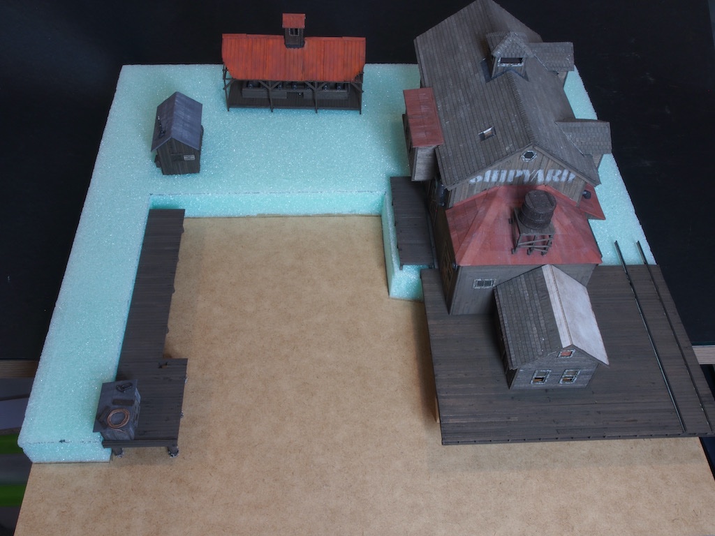
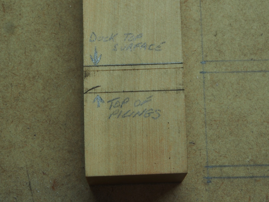
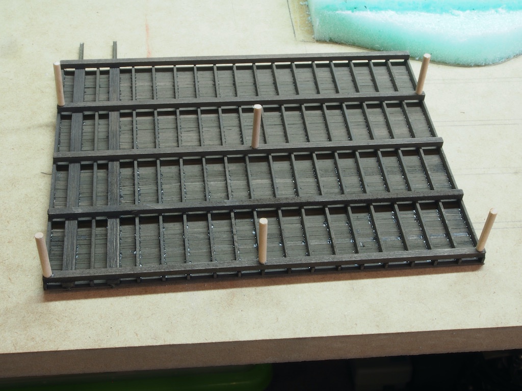
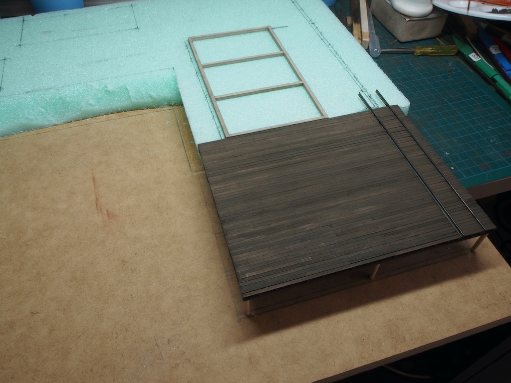
It's been a while since the last update, but that doesn't mean that I've been idle. Quite a few pics for this update, so I'll spread them over three posts. The Diorama Base Our attention now turns (temporarily) to the preparation of the diorama base. This starts with a base board of ¾” thick MDF cut to a size of 18” x 17 ½”. The instructions call then for two layers of ½” thick Styrofoam house insulation for a total thickness of 1”. I could only find 30mm thick stuff locally, so went with that instead. This is cut to a basic outline (shown with various measurements in the instruction manual) and glued to the MDF substrate. The instructions suggest using hot glue for this – I went with Elmers Glue-All (looks like a type of PVA) instead and this worked just fine. I couldn’t resist checking out the basic “fit” of the various structures at this stage. As the top surface of the main dock must be level with the top surface of the main building foundation, I made up a measuring stick to determine the height of some temporary pilings for the dock, taking into account the thickness of the dock main supports. A few of these temporary pilings were then spot-glued to the underside of the dock. The foundation epoxied in place, following exact placement dimensions from the instruction manual, and the dock test fitted to check alignment of the top surfaces. Another quick test fit of the main buildings, and all looks good. Some further shaping of the Styrofoam is then called for. This is simply achieved with a sharp snap blade utility knife and includes an initial rough shaping of the “pit” (where the ship under construction will be placed) and a “shelf” to allow the end of the dock to sit flush against the building foundation. I also gave the Styrofoam and base board a coat of paint, using some water-based artist’s acrylics. More to follow....
- 326 replies
-
- 15
-
-
-
Very nice work on the stern decorations Sjors.
-
Glad to hear you’ve finished mucking about with the EASY bit Glen. 😉 Looking forward to seeing how you tackle the hard bit.
-
Don’t know about Canada, but we all heard it Downunda too - along with the sound of the Scotch bottle being opened….
-
EURYALUS 1803 by Peter6172 - 1:48
gjdale replied to Peter6172's topic in - Build logs for subjects built 1801 - 1850
Nice work so far Peter.
