FriedClams
-
Posts
1,368 -
Joined
-
Last visited
Content Type
Profiles
Forums
Gallery
Events
Everything posted by FriedClams
-
 Beautiful work G.L. - and I echo the statements of others on the boats’ authentic appearance. The model looks absolutely real. Wonderful choice of woods and color tone. Sweet work! Gary
 -
A nice process for producing the frames G.L. and very clearly explained. With all the frames now placed, the shape of a graceful craft suddenly appears. Very nice work. Gary
-
Beautiful work Johann. I've been following along on your progress and find your attention to every detail inspirational. The wrap of every rope and the precise and elegant shape of every piece of hardware is so exacting and perfectly to scale. And thank you for taking the time to show us how you do it. Bravo! Gary
-
It looks smart to me Kees and the results are excellent. A beautiful model - an informative log. I will be watching for future updates. Gary
- 193 replies
-
- 3
-

-
- wilhelmina vii
- fishing
- (and 1 more)
-
I agree with Druxey - not gnash worthy, and dental work is so expensive. You’re moving along nicely on the model Eric and it looks great! Gary
- 599 replies
-
- 3
-
-
- sidewheeler
- arabia
- (and 4 more)
-
Beautiful model Dan and a very interesting and educational log. Congratulations on its competition. Look forward to your next build. Gary
- 238 replies
-
- 2
-
-
- leviathan
- troop ship
- (and 2 more)
-
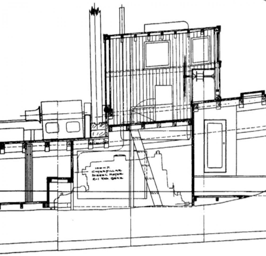
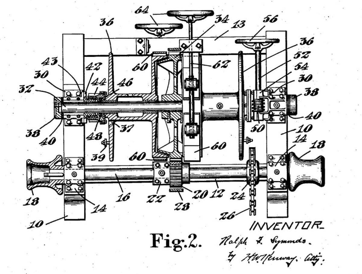
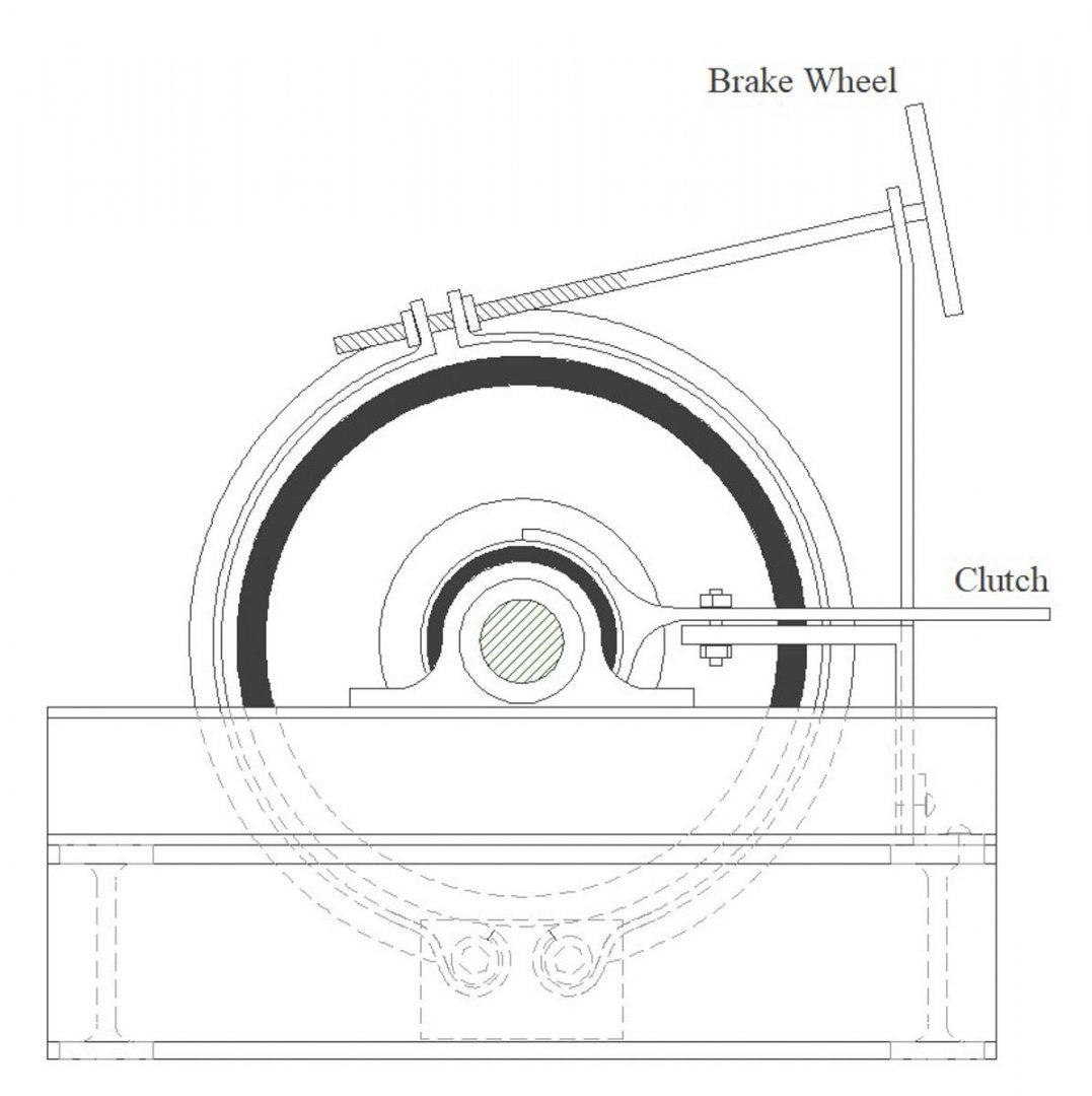
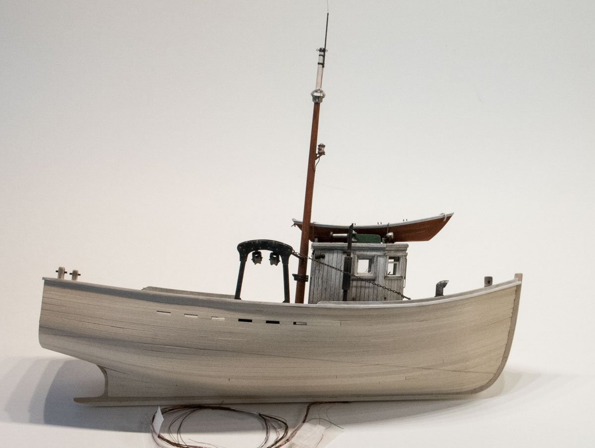
Keith, Michael and Druxey - Thank you so much for the nice comments and for your continuing support. And thanks to all for the "likes". Thanks Vaddoc and yes it has been a fun model to build. As far as the mast color goes, it wouldn’t have been my choice for the model, but it is a toned down compromise of the bright orange often used on these boats. I used acrylic here knowing that I was going to use dry pigment powder on top of it. If I were considering mixing the powder with alcohol, clearly a water-based paint wouldn’t work. I always lightly sand acrylic paint because I feel it brings the look down to scale, and even though pigment powers contain an adhesive component, a little extra tooth is always good. I think more grease than rust this time. Thanks John. That’s a good question Roger. The main engine supplies the power, but the actual power take-off configuration and how it mechanically attaches to the winch is something I haven’t seen drawn out. The drawing below makes me think it could have been a direct chain drive as there seems to be a PTO point on the engine just left of the text. The image below is from a 1928 U.S. patent submittal and it shows a winch with a sprocket and roller chain (items 24, 26) that the accompanying notes state is the power connection point. At first this sprocket/chain arrangement seemed grossly undersized until I noticed the small diameter of the pinion gear (20) and considered the huge mechanical ratio advantage it had to the large bull gear (34). So a chain drive off the main engine seems probable. And there must been a lever or something somewhere to de-couple the two. As a side note, the patent being applied for here was the idea of clutch surfaces that are integrated into the bull gear - one facing in each direction. The reels (36) are forced against the clutch plates with variable pressure by turning hand wheels (56). Hand wheels (64) are the drag brakes. Thanks for stopping through Roger. Gary
- 424 replies
-
- 16
-
-
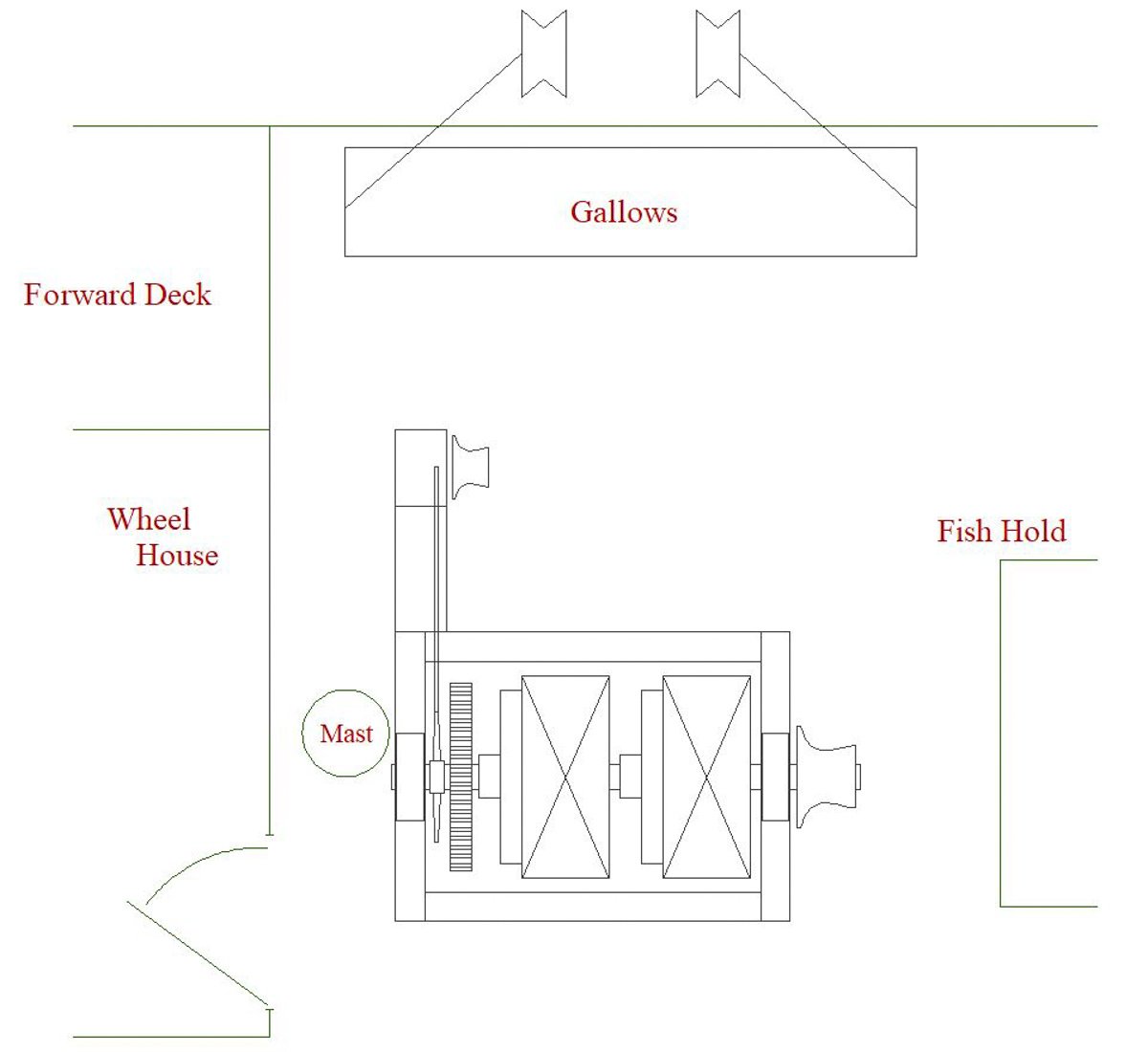
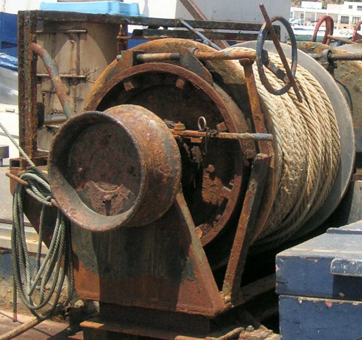
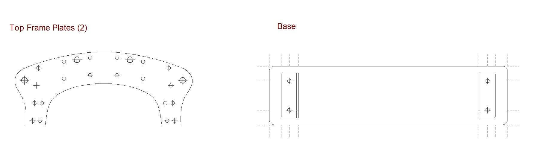
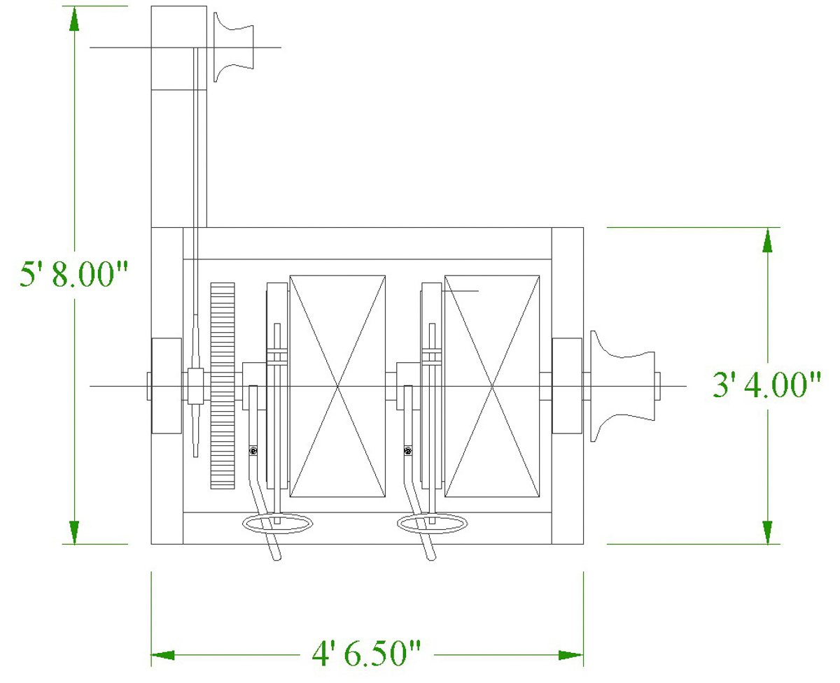
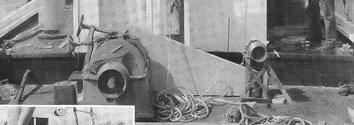
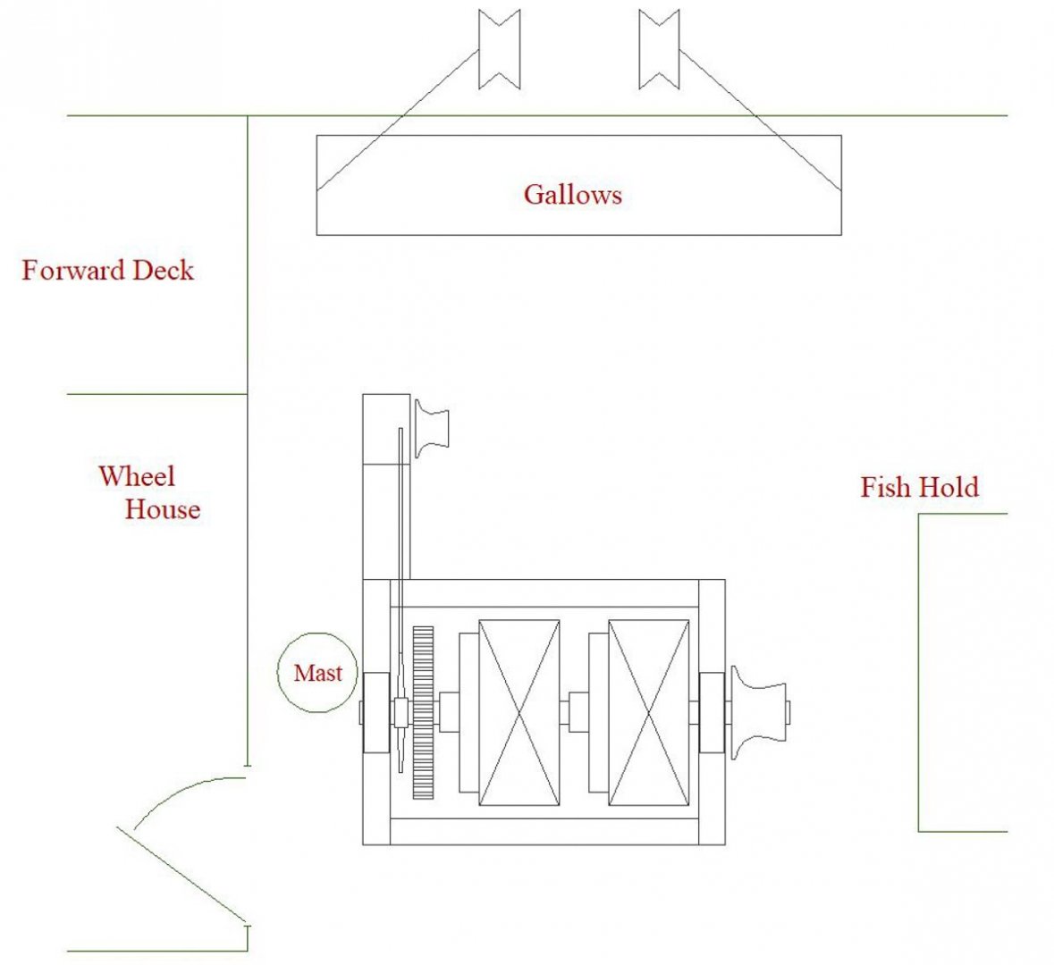
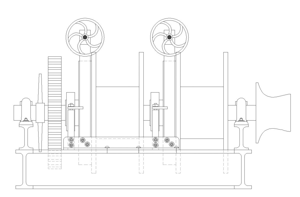
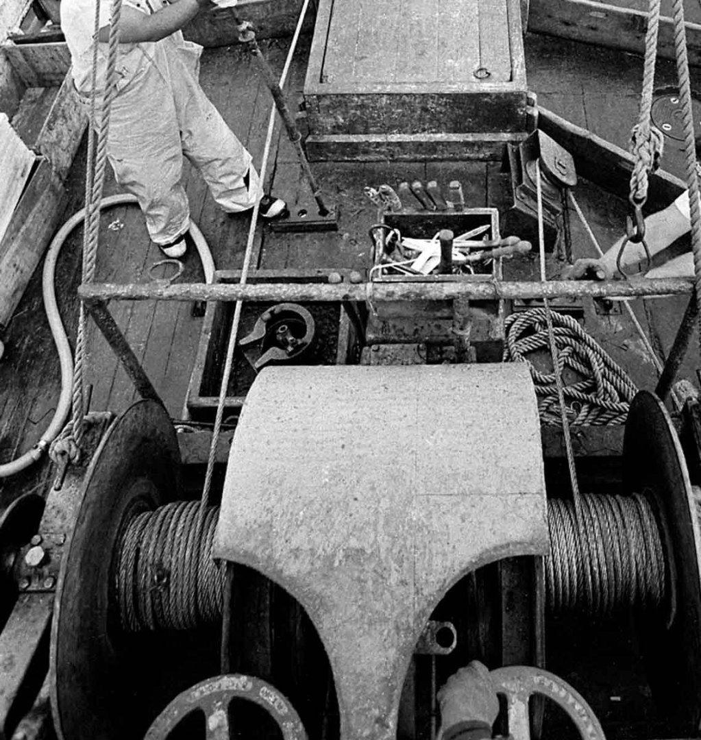
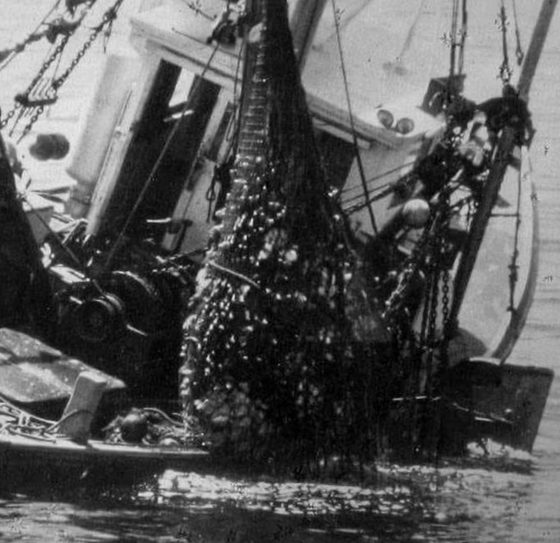
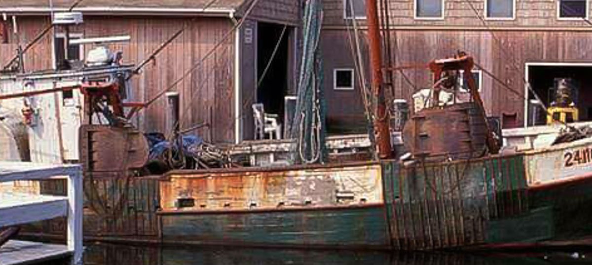
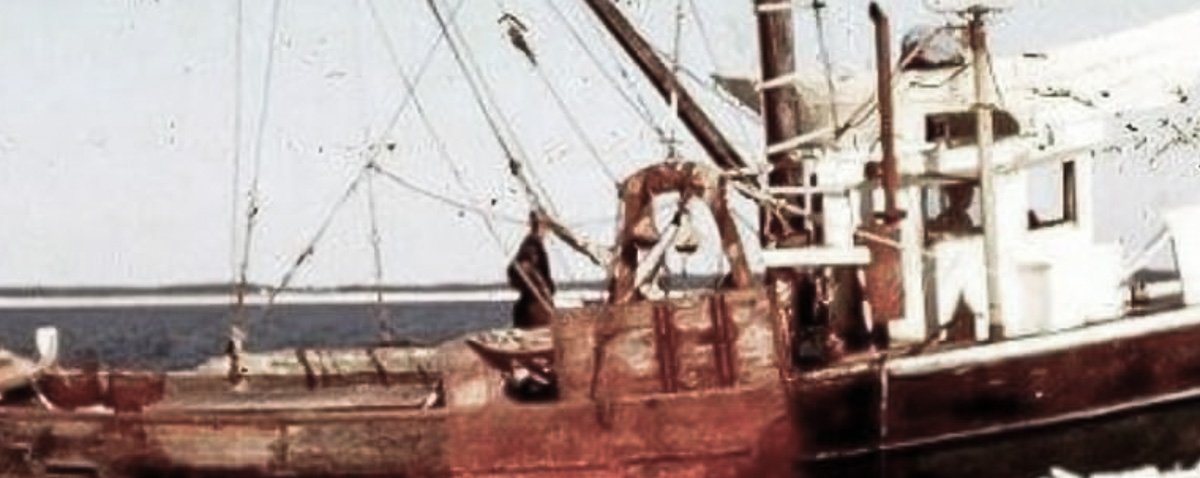
John, Keith, Mark, Moab, Jim and Alexander - thank you so much for the kind remarks and continuing interest in my model build. I truly appreciate it. And thanks to all for the "likes" and for swinging through. Here's a short update on the beginnings of the trawl winch. I’ve spent an honest amount of time digging up details for a winch to go on this model. Like the gallows frame, I didn’t find a standard "this is what everybody used" winch. If I could time travel back to southern New England in the 1920’s, I’m sure I would indeed find boats using standardized equipment. Hardware and especially machinery such as a trawl winch were most likely purchased from marine distributors or direct from the manufacturer. It seems unlikely a winch would be built locally. Fisherman needed a trawl winch that worked flawlessly and was practically indestructible. And repair parts had to be available off the shelf to the get the boats back up and running quickly. It would be great to have model numbers, catalogs, and exploded views of these winches, but I have none of those things. But the few drawings I do have include block outline dimensions of the winch and period photos show me what the winches looked like. So along with materials of more recent trawl winches, I have enough information to construct a winch that is at least historically honest if not precisely identical. These draggers were small boats and their gear was sized accordingly. Below is a plan view of the winch I drew up for this model. Though small, it is actually larger than some I have seen. Notice the auxiliary winch head at the upper left in this drawing. It is driven off the main shaft with a sprocket and roller chain. Here’s a small winch in place on a 1940s dragger. And here is how I will position mine on deck. These winches were pretty simple and consisted of drum reels with adjustable drag brakes and a clutch to engage them. Below is an end view of a 1960-ish trawl winch showing the clutch lever, the hand wheel for brake pressure and a winch head on the end of the main shaft. Here is my version of it. And then a side view. This winch has no automatic mechanism to spool the cable evenly onto the drum as it is being wound. This was common on these boats and may be because the reels were quite narrow and therefore spooling unnecessary. Also, on many of these boats the cables wind/unwind at a very steep angle directly to the towing blocks, so if any spooling was needed it might have been done manually with steel push bars. The image below shows the steep take-off angle of the winch to the towing blocks. Also, I like this photo because it shows a net heavy with catch almost pushing the rail of this little dragger under water. Below is a photo crop of a 1970s Cape Cod Eastern-Rig fishing boat. I wanted to show this image because it is the only one I've seen showing the use of steel bars to guide the cable onto the winch reels. Notice that the foot of the bar is placed into a wooden plate with sockets providing a choice of leverage positions. In 1:48 the winch for my model will be a little over 1-1/8” by about ¾”. In the next post I'll make up parts and put it all together. Thanks for stopping by and have a wonderful new year. Gary

- 424 replies
-
- 14
-
-
Hello Phil, I've been following along on your build and it's coming along very nicely indeed. Your painting of the grenadier is top notch - the coloring is perfectly subtle and subdued, and the shading is spot on. I wish you continued success. Gary
-
Beautiful work Michael - every bit of it. Walter is living in the lap of luxury. Gary
-
Nice neat work Danny - everything fitting together cleanly and accurately. Seeing the boiler propped up on your bench really gives a good indication of the model’s size. It is a little larger than I was imagining. Looking great. Gary
-
Very interesting log you have going here Vaddoc and a handsome subject vessel it is. I admire your CAD skills and perseverance in getting the drawings just so, and sInce you asked, I like the Swiss pear and birch combination for their tonal and grain qualities. The more prominent grain patterns of beech and cherry could possibly look out of scale. Looking forward to future updates. Gary
-
Terrific work on those globe valves Keith, and a nice exacting process for the bowsprit cutout. Top notch beautiful work as always. Gary
-
That really is quite a nest of chain, rope, hooks and eyes - but it turned out very nice Keith and neatly done. My experience has always been, that what ever time I predict any task or project will take, I should just double or triple it. It always looks easier in the imagining. Happy Holidays. Gary
-
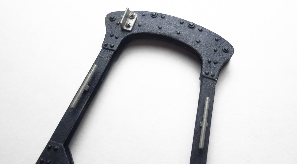
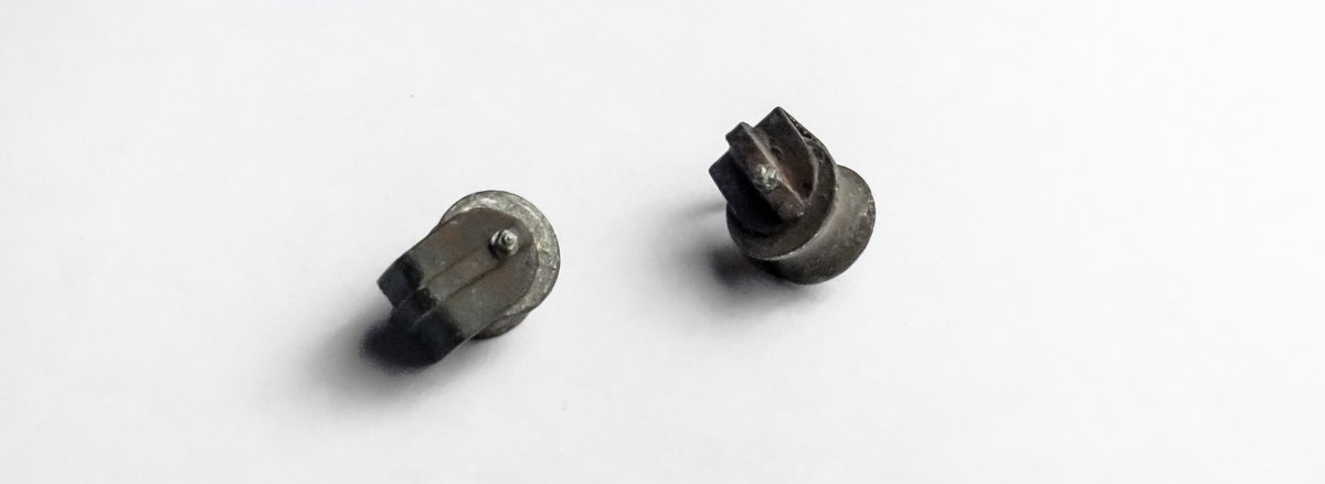
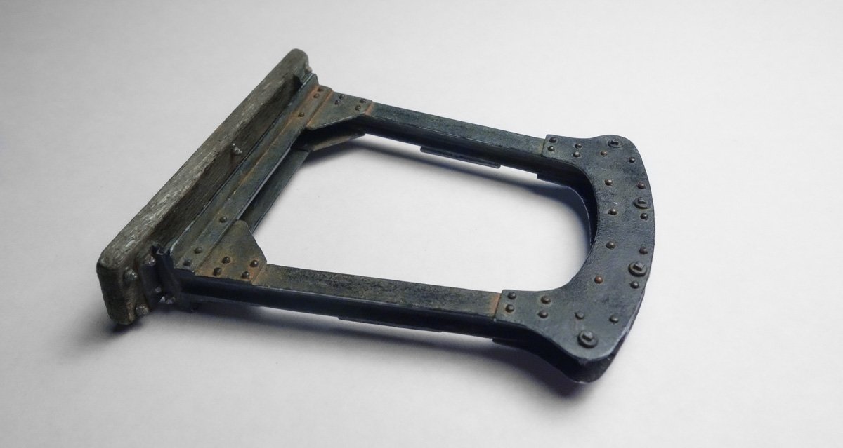
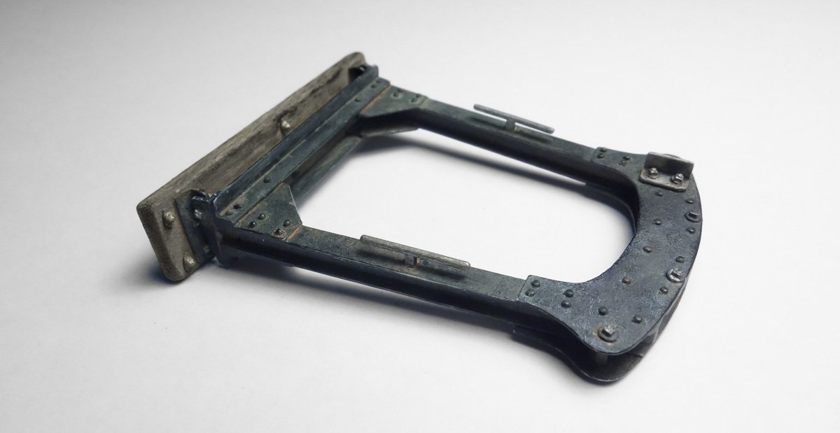
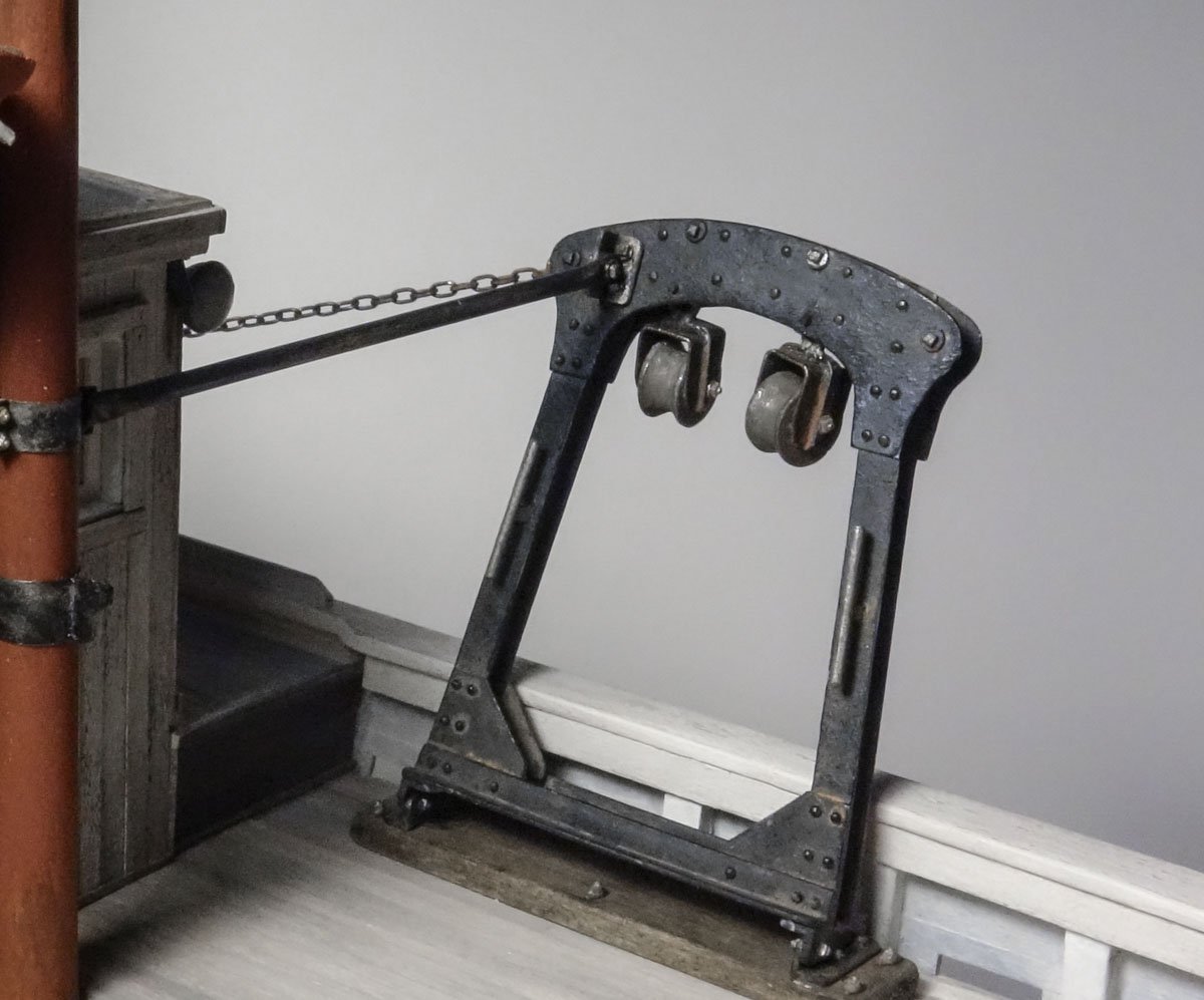
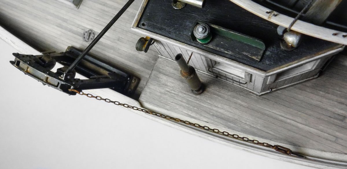
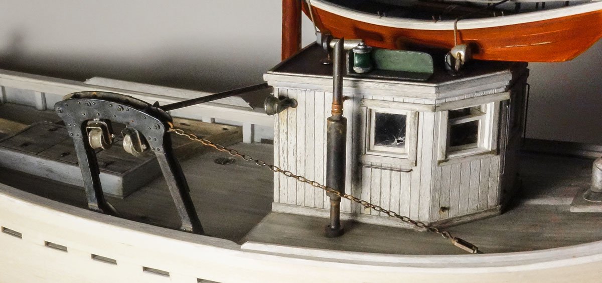
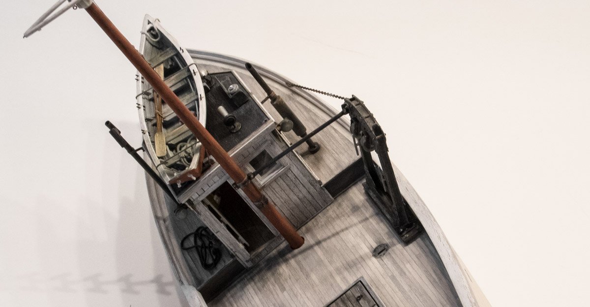
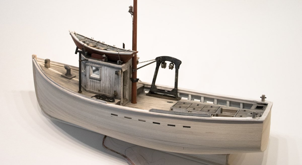
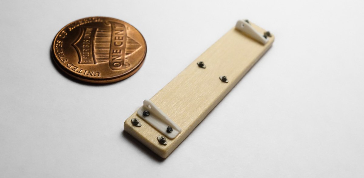
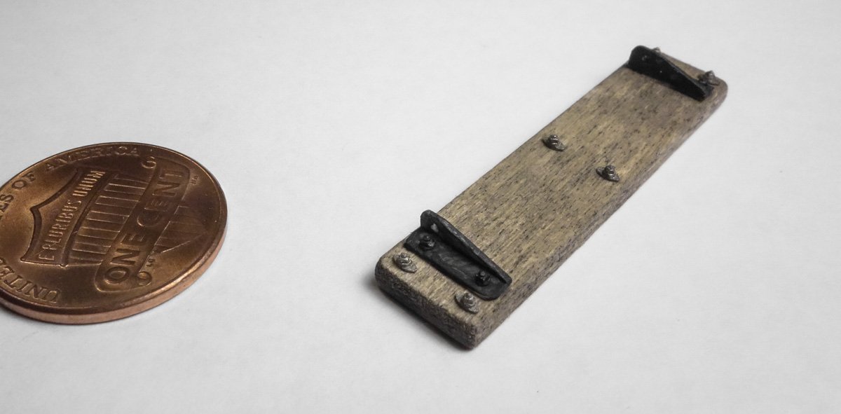
Thank you John, Chris, G.L., Keith and Michael for your nice comments and support. And thanks to all for stopping in to take a look. Finishing the Gallows Frame Here is a small update on the dragger. Some cleats and an angle iron bracket for the mast brace were made from styrene and glued to the frame. A very thin wash of acrylic was applied to give it a barely perceptible hint of blue. Then a little rust and dust was added with pigment powders. The reverse side. The tow blocks are made from styrene and wood dowel. The pulley sheaves needed to be a scale 12” diameter so ¼” dowel worked out perfectly for this. Black primer and “steel" enamel along with a couple of dirty pigments completed the look. Blackened copper wire was bent into eyebolts and attached to the top of the tow blocks. These were then pinned into the gallows frame with brass rod and are allowed to dangle freely. The frame was glued to the deck and a short piece of brass tubing representing a 2” pipe brace is rigged between the frame and the mast. The deck surrounding the gallows frame will need some additional coloring and wear, but that will be done after the winch is made up and placed. This image below provides a good look at the forward support chain. I really like this miniature chain because it has elongated links like real chain. More often than not, tiny scale chain is comprised of links that are round (and sometimes flat) and doesn’t replicate real chain very well. This chain is pre-blackened, 15 links per inch, #29221 from A-line in California. A little rust colored pigment was added to the chain and turnbuckle. In this top view you can see how the support chain attaches to a post that is bolted between the two gallows frame head plates. The forward edge of the chain terminates at a turnbuckle. From there a rod penetrates the covering board at the same steep angle as the chain, and presumably bolts through a heavy timber below deck. And a couple more views. And finally, I would like to wish everyone a happy and peaceful holiday season. Gary
- 424 replies
-
- 31
-
-
Your deck is looking great Keith - populated with small clean details. I do like your card method of symmetrically locating the plinths. Many times I've glued on tiny parts like these only to later find that they slid just slightly from position as pressure was applied. Resting the part up against the card edge would solve that problem as well as accurately locate it. A simple and clever solution. Thanks. Gary
-
Thanks for the additional information on your casting procedure G.L - I appreciate it. I can think of several applications where this type of mold casting would be useful. Gary
-
Very nice detail with that metal keel G.L. The bar tin that you used - was that a 50/50 tin/lead or a lead free bar at 97% tin, with antimony/copper/silver? The reason I ask is because it seems to have flowed into your mold quite nicely. I would have expected lots of air bubbles and voids. Also, I noticed the wood plug you used to form the plaster mold is shiny. Did you slather the wood with petroleum jelly or something else as a release agent? Enjoying your log. Thanks Gary
-
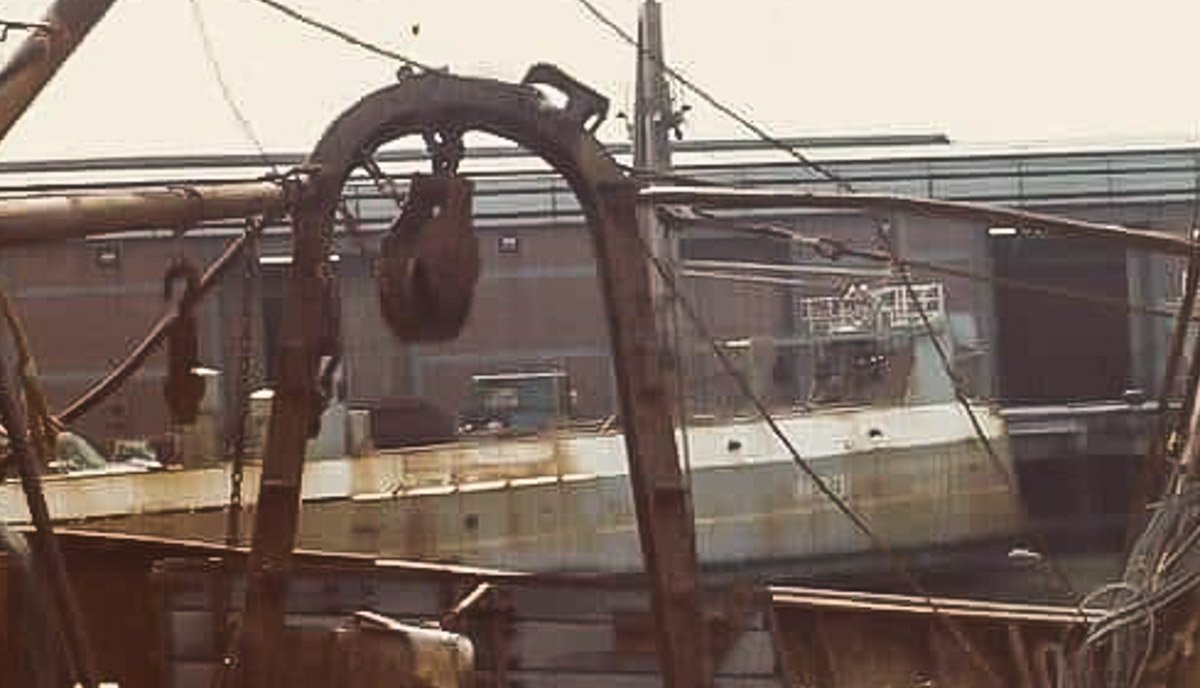
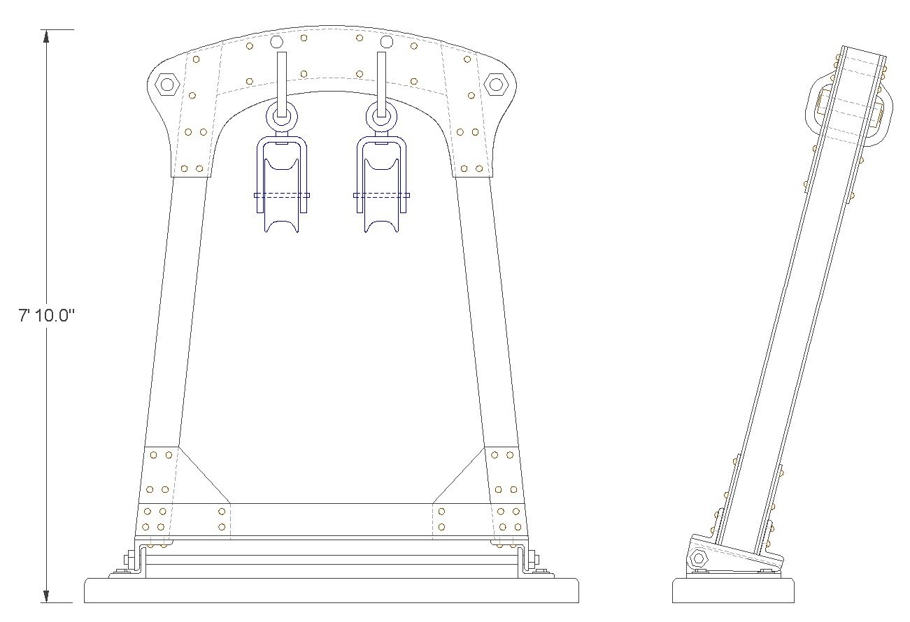
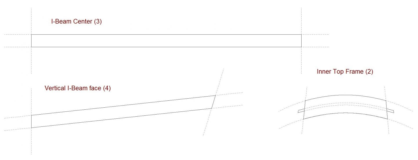
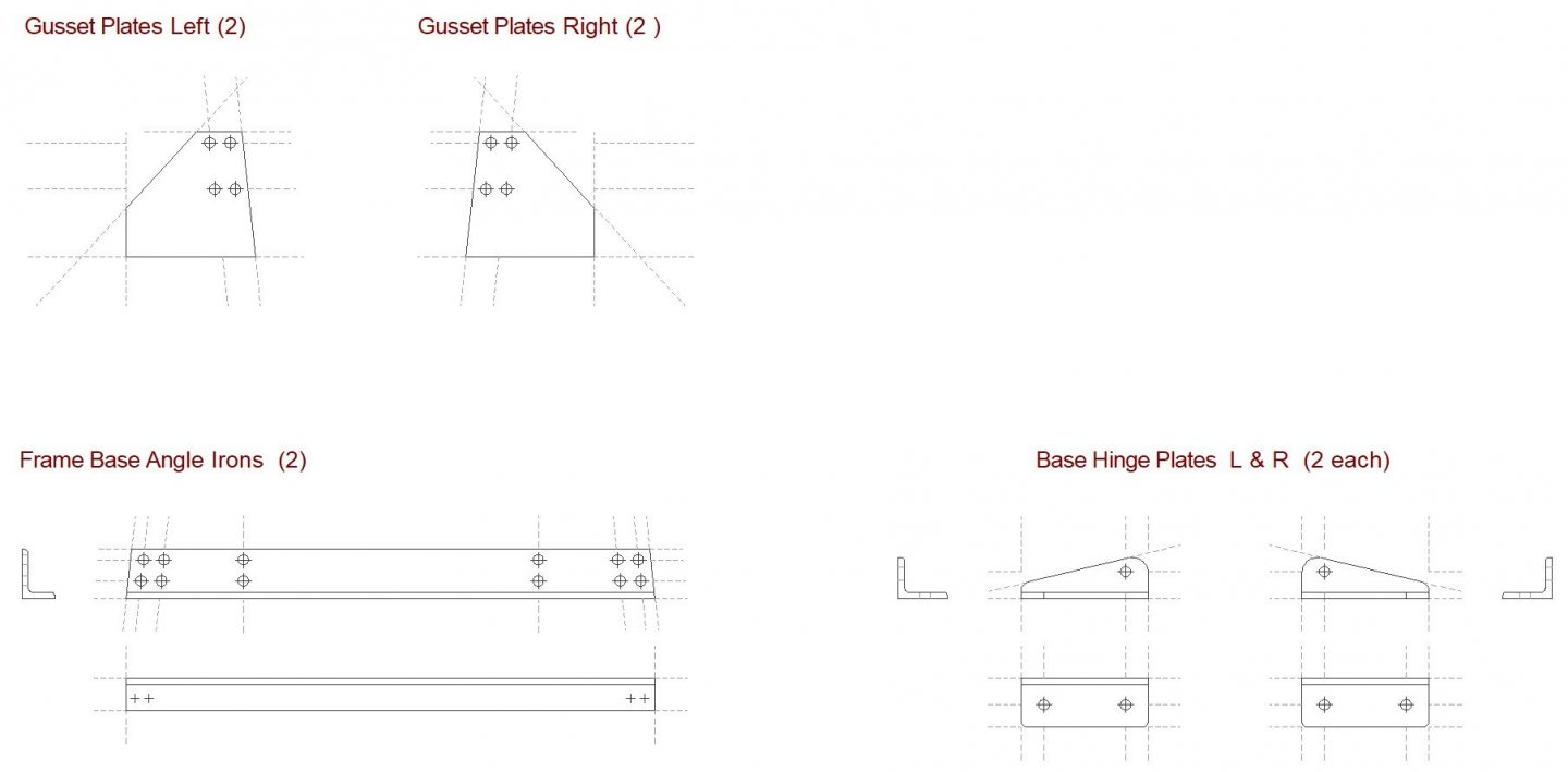
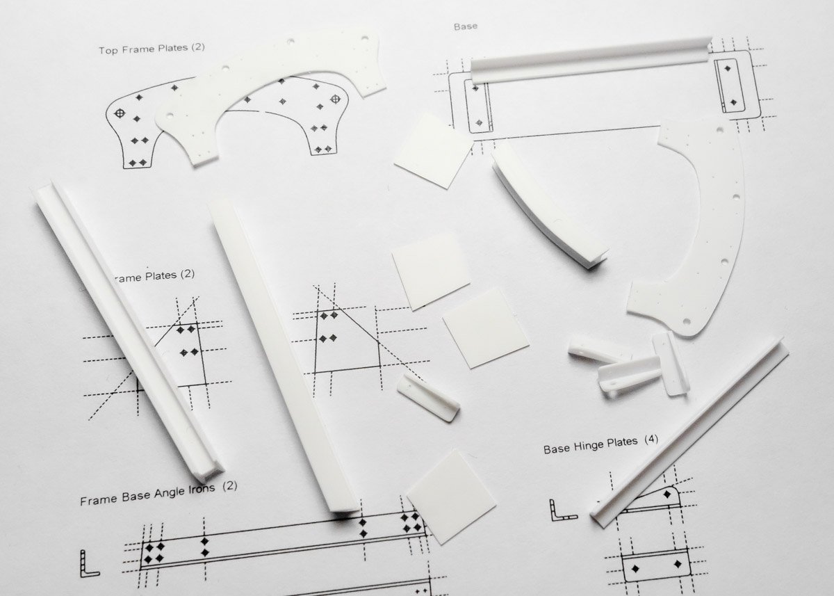
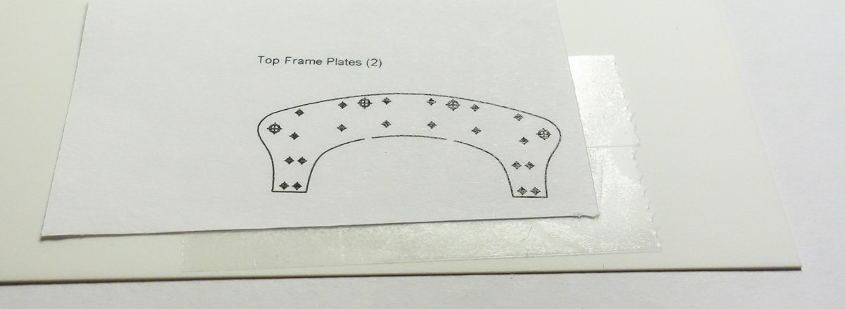
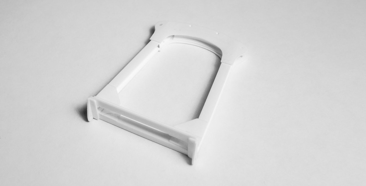
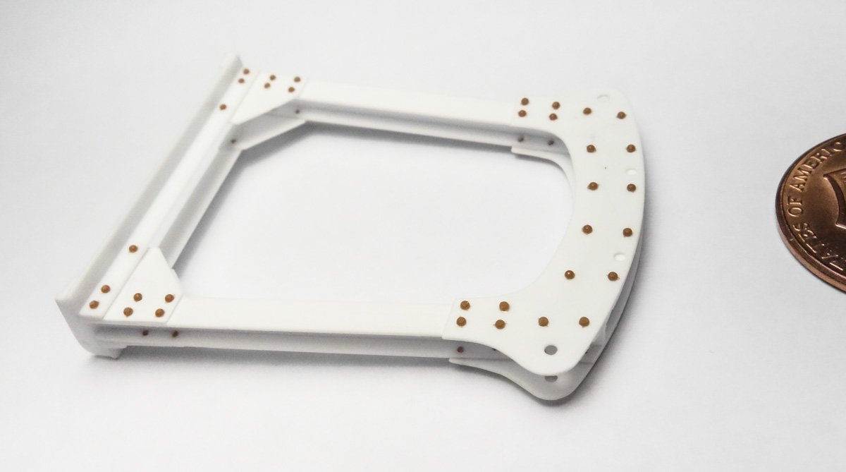
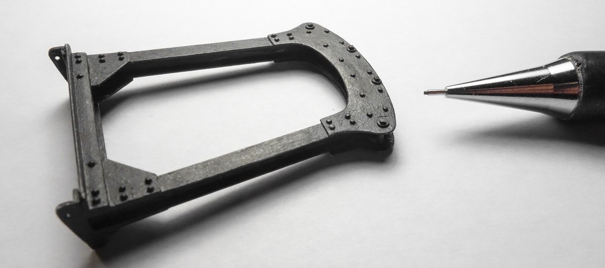
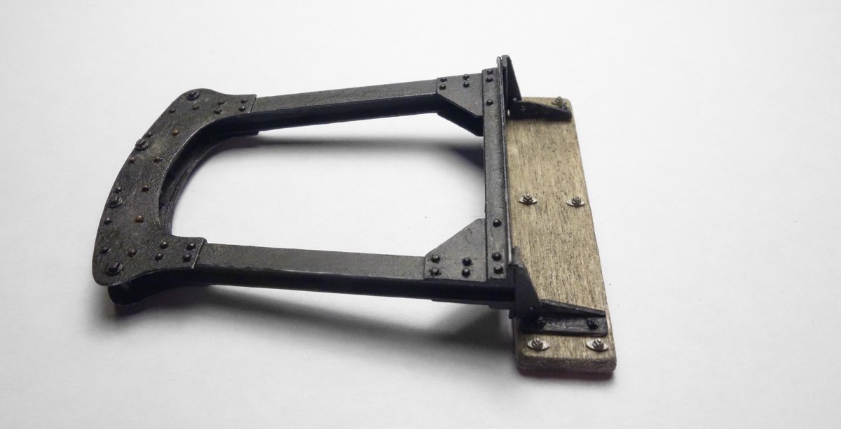
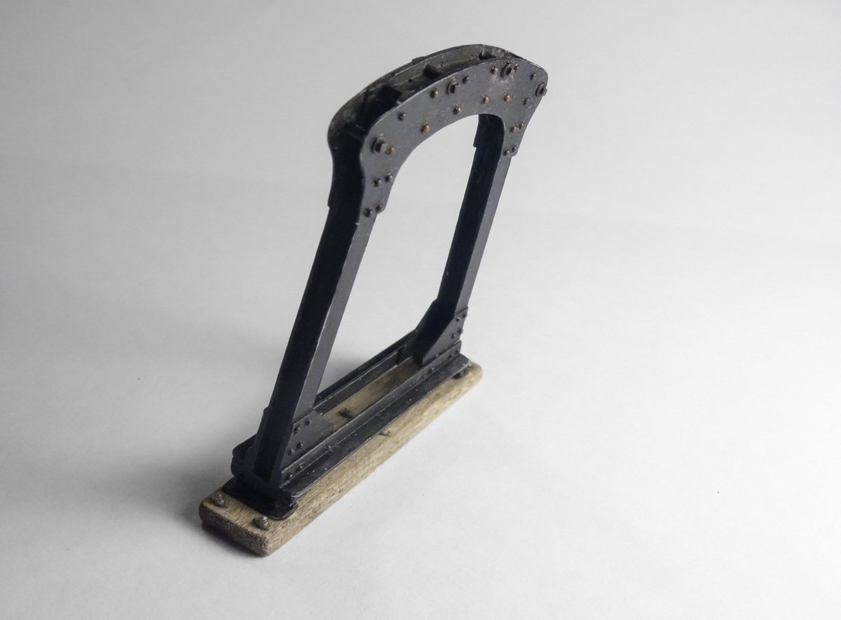
Thanks to everyone for looking in and for the likes - I appreciate it. Gallows Frame This model represents a fishing boat typical of its type in the 1920s. Details on boats from the 1940s or 50s may not be historically valid for the era of my model. I found this to be true when considering the gallows frame construction. It is easy to forget that a technology as commonplace today as arc welding, really hasn’t been around for all that long. Even though the first U.S. patent for arc welding was awarded in 1890, it was still in its infancy in the 1920s and many important improvements were years away. Steel joinery in the 1920s was mostly riveted, bolted together or forge welded. So construction of the gallows for this model will be riveted I-beam, angle iron and boilerplate - nothing welded. After looking at many gallows frames, I came to discover that no two are alike unless they were on the same boat. Evidently, there was no “Acme Gallows Frame Company" and every port had its own millwrights/smiths constructing frames for their own local needs. But the frames generally fall into two basic styles – the inverted "U" and what I call the three-piece Stonehenge. The photos below show these two styles. I apologize for the poor quality of the images. With some uncertainty I decided on a modified Stonehenge design. One criteria for the frame was that it be strong enough to support both towing blocks. Most trawl fishing boats carry two frames - one for each block, each towing one door (otter board). Photos of 1920s Western-Rig Stonington boats are rare and ones detailing trawling hardware are all but non-existent. But this photo (1950s?) shows what I believe makes realistic mechanical sense in terms of size and heft for a two-block frame. I drew up the frame below using the above photo as a guide to what I wanted the end result to look like. The overall dimensions of the frame and the size of the steel used to build it, came from referencing photos of newer boats and a drawing of a 1920s auxiliary fishing schooner. The towing blocks in the drawing may seem quite large, but it matches what I found were actually used. The pulleys alone are 12” in diameter and had to handle both wire cable and chain. Consider the strain these blocks had to withstand reeling in tons of fish in a net that trailed a mile behind the boat. The forces on the blocks, frame and the boat in general must have been enormous when the net gear snagged ledge or rock outcrop. But still, when I get around to making the blocks, I’ll scale the size back if they just look too large. I then pull apart the drawing and make cutting templates for the individual pieces. The frame I-beams. The gusset plates and angle iron. And finally the top frame head plates and base. All the small center marks indicate rivet or bolt locations. The pieces are cut from styrene and a dressers' pin is used to mark the rivet/bolt locations. The only fussy pieces to cut were the two head plates. Double-sided tape was placed on the sheet styrene and the template placed on top of that, then cut through with a scalpel and finished off with needle files. Everything is assembled. Holes are drilled at all rivet locations and styrene rivets glued in. The rivets scale to 1.25” in diameter. The base is made and styrene N/B/Ws are added. The frame is painted flat black enamel. This is only a base coat and additional washes and weathering will be applied later. The frame base is stained and the hinge plates and nuts are painted. This also is just a base color. Here the frame is temporarily placed on the base. Why the builders of these gallows went through the trouble of making them hinge and swing down flat is a mystery to me. In every photo I have seen of these frames they are shown chained, braced with iron pipe, and in one way or another reinforced to prevent collapse and from being torn off the boat. They appear to have never once been moved since the day they were installed. But there must have been a good reason for installing hinge plates. Standing up and leaning forward in the dragging position. Still to be done are the tow blocks and their attachment points on the gallows, some frame cleats and the rear brace that secures it to the mast. Also some chain reinforcing. The last step will be to add a color wash then weathering and rust the whole mess. It needs to look worn and worked hard before it is placed on the boat. Thanks for swinging by. Gary

- 424 replies
-
- 25
-
-
What an insightful observation G.L. and it put a smile on my face first thing this morning. I think most people love small boats. Perhaps it has something to do with childhood and remembering the first time you tentatively stepped barefoot into a row boat on a summer morning in a world without cares. The oar lock plates are an elegant detail and I like the sheet traveler as well. Gary
-
Hello Eric, I’ve been reading your build log from the beginning over a few sessions and just now caught up. This is a very interesting subject and your model is looking great. I love the look, history and nostalgia of these old steamboats. Every time I see an image of one, I can’t help but think of Mark Twain and his wonderful book “Life on the Mississippi”. Your log is both fun and educational. I look forward to future updates. Gary
- 599 replies
-
- 5
-
-
- sidewheeler
- arabia
- (and 4 more)
-
Very nice job on this model Popeye. It is an interesting lighthouse design and it’s coming together nicely. Great job on the B17 and steam locomotive by the way - they both turned out great. Gary
-
Beautiful job on this model CDW. In so many of the photos it looks just like the real thing. Fantastic job on the paint. Gary
-
Just found this build log Danny, and I am very impressed with your construction of it and the look of the model in general. I am always amazed by how realistic these card constructions can be - and how detailed and complex. Very nice work indeed and I look forward to future updates. Gary