HOLIDAY DONATION DRIVE - SUPPORT MSW - DO YOUR PART TO KEEP THIS GREAT FORUM GOING! (Only 13 donations so far - C'mon guys!)
×

rdsaplala
-
Posts
602 -
Joined
-
Last visited
Content Type
Profiles
Forums
Gallery
Events
Everything posted by rdsaplala
-
 Very nice video, Mark, these pumps sure are ingenious inventions, thanks for sharing the link
 -
Hi Mark, Just catching up, beautiful work on the pumps my friend, very innovative use of materials too I really like this French set up of pumps, this is the first time I've seen such set-up and it provides an interesting change from the almost generic 2 chain pumps plus 2 elm pumps set up so often seen in English frigates and sloops
-
Pleased to know you've fixed the mizzen top mast successfully Peter, it should be pretty strong once all the standing rigging is in place. Your top mast looks magnificent Sir, excellent detail work
-
Thanks very much for the tip on scroll-sawing, Danny, I'll give it a try Those bulkheads look great Sir, they fit perfectly like gloves which is no small feat given the complex shape of the inner bulwarks. Upper counter planking is also coming along very nicely, great work!
-
Hi Anja, Amazingly clean and beautiful planking work there, Ma'am, Half Moon is really coming along very nicely Aaah and I see you've succumbed to the force of the darkside, I guarantee you're gonna love it there and with the help of those excellent tools you have, I'm sure you will tackle your first scratchbuild with flying colors
-
Beautiful, clean, and very fast work on the decks and stern, Popeye, you are on fire my friend!
-
Great work Sjors! You've shown those shrouds who's boss, they look very well done
-
Beautiful planking work, Mobbsie, Aggy looks awesome! Wow! I never realized that a ship of the line required so much planks, and that's only below the about 2/3rds of her You have the perseverance of a saint, my friend, excellent work!
- 1,279 replies
-
- 1
-

-
- agamemnon
- caldercraft
- (and 1 more)
-
Shrouds are looking great, Andy, well done
-
Thanks for the clarification, Russ, my apologies for using a Swan Class vessel as an example, I have removed the pics to avoid any further confusion.
-
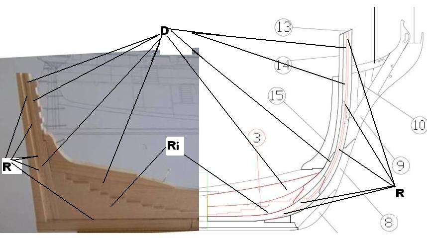
Hi Guy, Here's my take on the thicknesses of your component parts (Russ, kindly correct me for any mistakes in my interpretation). As seen in the pic below, you basically just repeat the same thicknesses you did with the stern. Deadwood and adjacent components (D) would follow the same thicknesses as your stern and ends up as a deeper notch at the Rabet ( R ). Rising wood (Ri) is slightly thicker than deadwood and tapers down as you approach the Rabbet ( R ). Like in the stern, the rabbet at the stem is basically the same thickness throughout:

-
Definitely Caldercraft. Yes, the instructions are not that much, but you could basically build her without instructions given the detailed plans that they have. Also, I remember that before the great crash, there are plenty of buildlogs that can help address any questions you may have.
-
Thanks for dropping by Sjors, don't mind the technical discussions my friend, they are just my vague way of saying I made a bit oooops in modifying my ship
-
Go for the Triton, Fam, she's a beautiful ship and there is a complete set of "as built" line drawings including all decorations for her as well as deck plans. In addition to this, there is also a disposition of frames plan for the Modified Mermaid Class, to which Triton belongs. These can all help supplement the provided MSW plans. My mistake was to use "as proposed" line drawings for the Modified Mermaid Class to revise my bulkheads. While test planking shows that my new bulkheads will produce a considerably fairer hull without any awkward bulge, I still have to live with the fact that "as proposed/as designed" plans only rank second to "as built" plans in terms of accuracy All is not lost however as a fine gentleman named Christian will be re-drafting a high resolution "as built" draught of Triton to correct any distortion. Once completed, this redrafted plan will serve as an excellent basis for me to re-make all my bulkheads and centerboard (Thanks again in advance for the help Christian ) Of course these things take time so while waiting, I have the option of proceeding with my current hull as practice or building a POB model of this famous 24-gun frigate from plans made by John McKay The redrafted plans have no distortion so making the bulkheads is pretty straightforward:

-
Beautiful weathering Daniel, everything looks so real I could almost hear Admiral Nelson giving some orders to the crew to scrub away the grim and repaint his ship... I hear he's quite particular about keeping his ships neat and tidy
-
I agree with Chuck's statement, it basically depends on which method you are most comfortable with and of course how well your final outcome turns out. I have seen so many beautifully made hulls using the POB method and a couple of terrible looking POF hulls. I my case, I have very limited tools and carving skills so I find that POB is the most practical approach to create an accurately shaped hull since I could easily use the cross sections in the draught's body plan as patterns to cut my bulkheads. It would be more difficult for me to carve a solid block of wood to conform to the plan's lines given my limited tools and carving skills. Just my two cents. By the way, that's a very nice model you have there
-
Hi Frank, Thanks for the good word, my friend, they are always much appreciated To be perfectly honest, I don't feel so amazing after my recent lapse in judgement of using an "as proposed" set of plans instead of the more ship-specific "as built" plans to modify my bulkheads, but I think a few nights having my fill of alcoholic beverage should fix that
-
Wow! That's great Christian, thank you very much, both my fingers are crossed my friend
-
Hi guys, Sorry for the confusion my last post has caused There is indeed only one set of plans specific for Triton as built (it's plan ZAZ3235 and is the plan I recently ordered and am waiting for to arrive). I have edited my previous post accordingly, thank you for the clarification, Christian Fam, you are correct, there are some differences in the two plans, most notable of which, are the details in the quarter galleries. Dang, it completely slipped my mind, I was so busy revising my bulkheads that I forgot that I am using the "as proposed" plan for the Modified Mermaid Class when I should have waited for the "as built" plans to arrive before revising any bulkheads The lines look the same at first glance, but I am almost 100% sure that there are bound to be some differences upon close inspection. Oh well, I may be looking at another redo of my bulkheads (or make that entire model) once my plan ZAZ3235 arrives. Ah yes, fun fun and more fun... Does anybody know where that emoticon of "hitting my head with a hammer" is? I think I could use it right about now
-
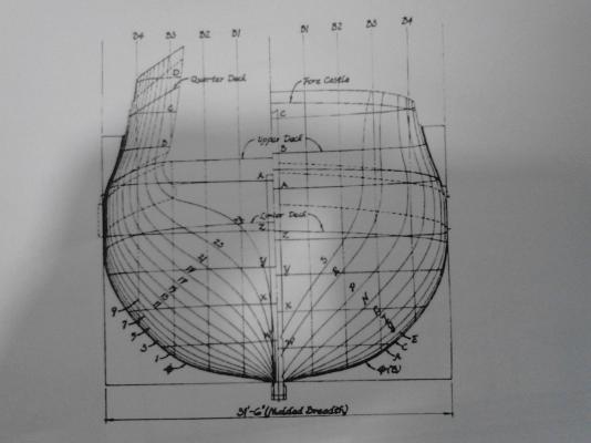
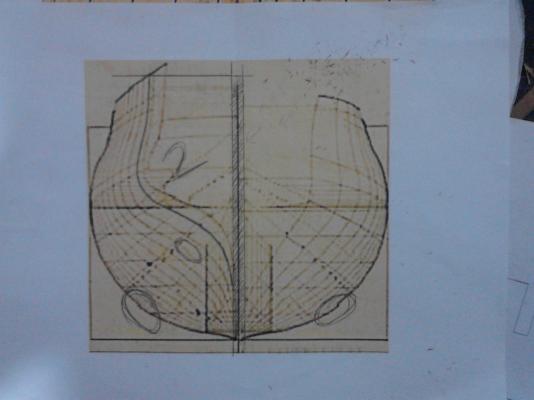
Thanks for the reminder on securing the bulkheads, Fam, I will keep that in mind Yes, these distortions in the sections can be a real bugger, the particular draught that I used for the bulkheads is this 1773 plan: the actual plan is about 1 1/2 foot long and the bulkheads seem to have no distortion at that size, unfortunately, enlarging the plan seems to emphasize distortions, which were previously not visible The good thing is the minor distortions are correctable using the corresponding waterline measurements in the halfbreadth plan, which luckily is not distorted I see that you have the 1771 as built plans, I'm pleased to know that it has no distortion. That is the particular high resolution plan that I purchased from NMM a few days ago, I am hoping that this plan will still have no distortion at high resolution as I will use it to re-evaluate all my bulkheads EDIT: Just a small clarification; The plan that I erroneously called 1773 plan is NMM's Technical Drawing ZAZ3240 "as proposed" for the Modified Mermaid Class Ships: Triton (1773), Greyhound (1773), Boreas (1774) ). http://prints.rmg.co.uk/art/493990/Triton_1773_Greyhound_1773_Boreas_1774 The plan that I called 1771 as built plan is draught ZAZ3235 for Triton (1771) as built by MBs Adams at Bucklers Hard: http://prints.rmg.co.uk/art/528431/Plan_showing_the_body_plan_stern_board_outline_sheer_lines_and
-
Thanks for the encouraging words, Robert, all this new learning on plans can be a bit tedious, but fun and exciting nonetheless Thank you very much for the help on the drawings Christian, I sent you a PM
-
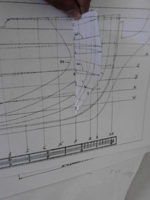
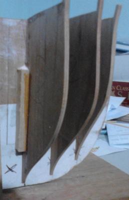
Thanks Christian, I'm pleased to know that you plan to correct the offending frames on Triton, that'll be of great help to all builders of this beautiful ship. Also if by some chance you decide to re-trace the Profile, Half-breadth and Body plan of Triton on CAD, and correct the distortions, I hope you won't mind sharing them as they would be of great help in making a more accurate centerboard and set of bulkheads Thanks Fam, CAD is indeed the most accurate method for re-drafting new bulkheads 24 and 18, it's included in my priority list of "things to learn" For now however, given my zero knowledge on CAD, I came up with a low-tech approach to correcting all involved bulkheads without any re-drafting. This was to make a new centerboard with no open slots then mark the stations of the draught directly onto the centerboard: This basically allowed me to use the provided sections in the draught to make "half bulkheads" and stick these directly to their corresponding stations in the centerboard: As seen in the pic below of the front bulkheads, I basically disregarded the bulkhead slots in the centerboard and just attached the new bulkheads traced from the draught onto their corresponding stations: A downside to this is the stations are pretty close together so I have to use thinner bulkheads to avoid fouling the gunports. Another major limitation is that I have to choose my bulkheads carefully, making sure I don't use the distorted ones (encircled) Knowledge on CAD would have been very helpful in correcting all these distortions thereby allowing me a wider selection of bulkheads to choose from... of course, if anyone knowledgeable on CAD is willing to volunteer retracing my new draught when it arrives, and correcting all the distortions, I'm just a PM away
-
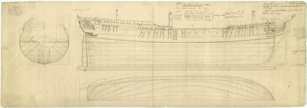
Hi Christian, no I bought another hard copy from NMM, but this time larger in size, at about 1m x .4m, it's much larger, and hopefully with clearer details than my current draughts (see below): http://prints.rmg.co.uk/art/528431/Plan_showing_the_body_plan_stern_board_outline_sheer_lines_and Unfortunately, it's also a bit more expensive than my previous purchases : Once this set arrives, hopefully in a month or so, I will also scan them and resize them to 1/64
-
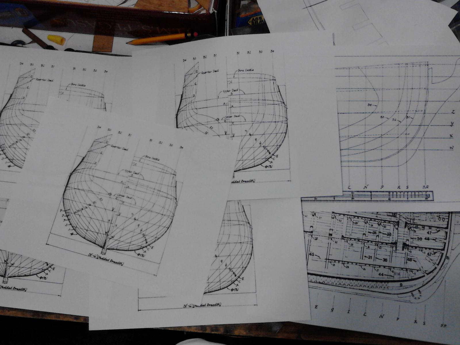
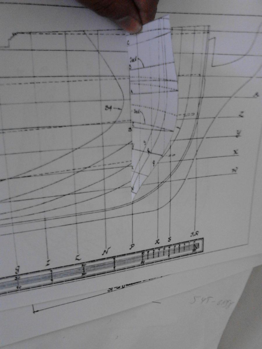
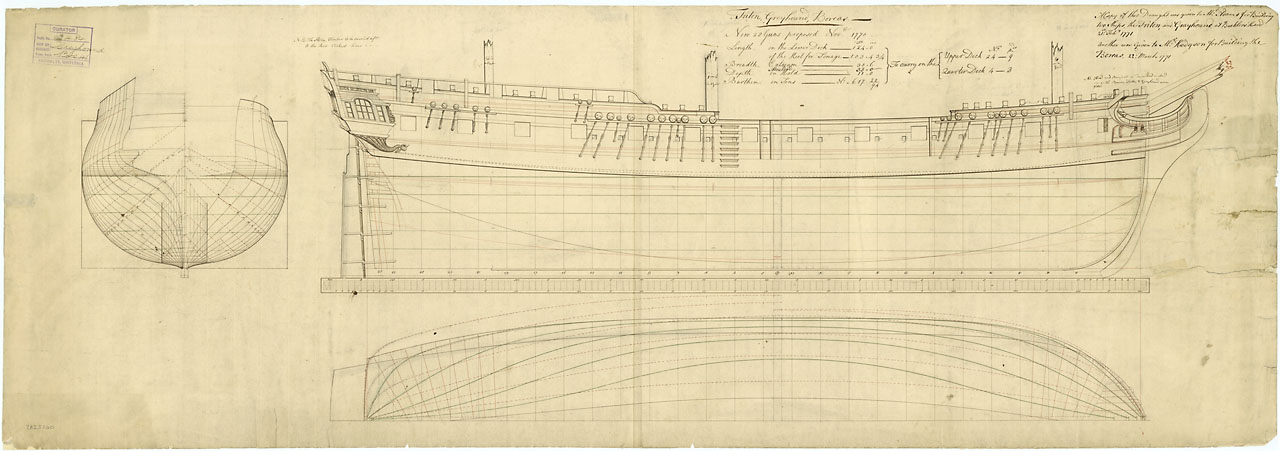
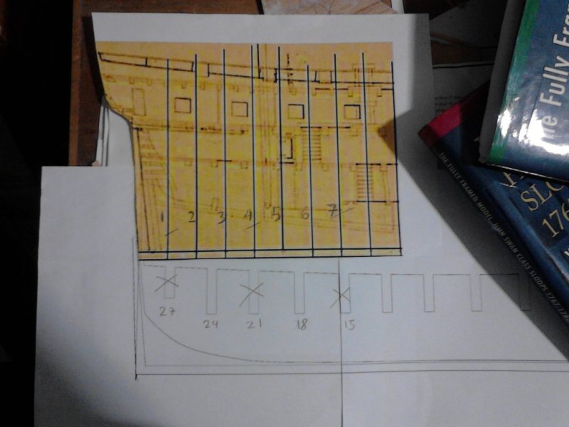
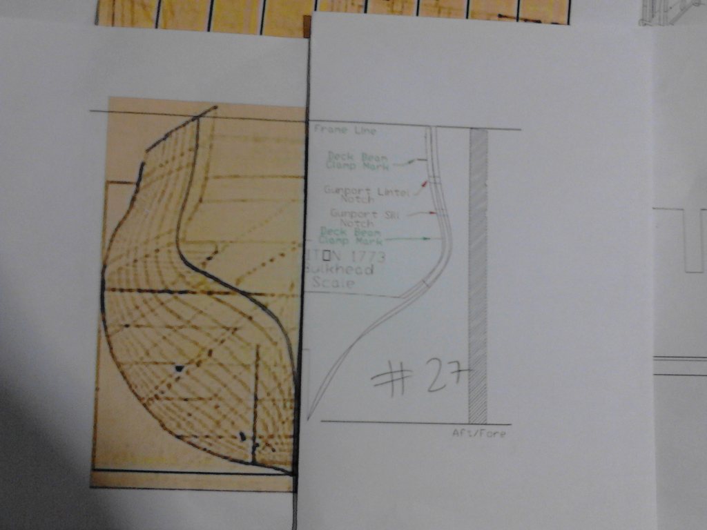
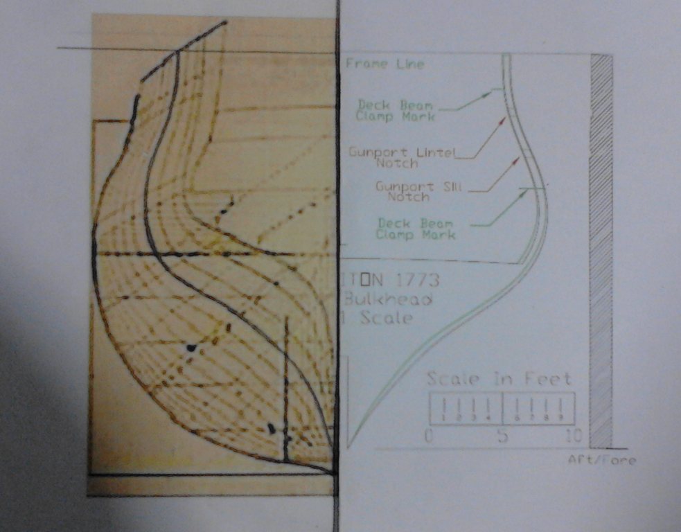
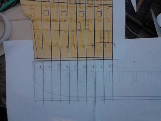
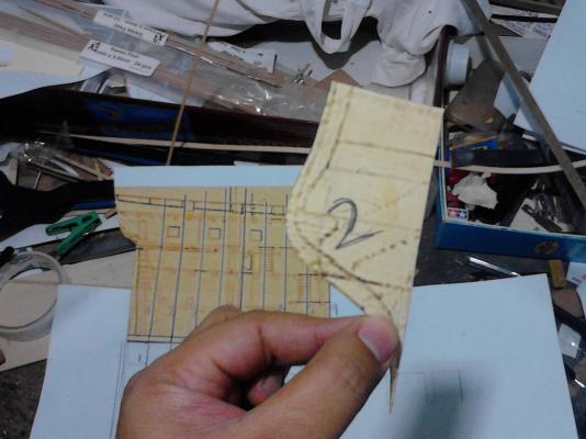
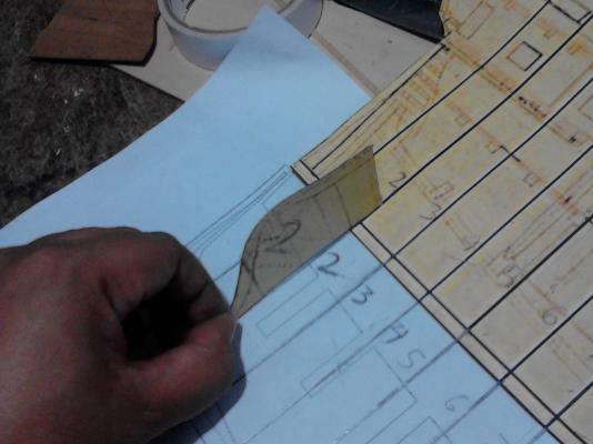
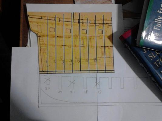
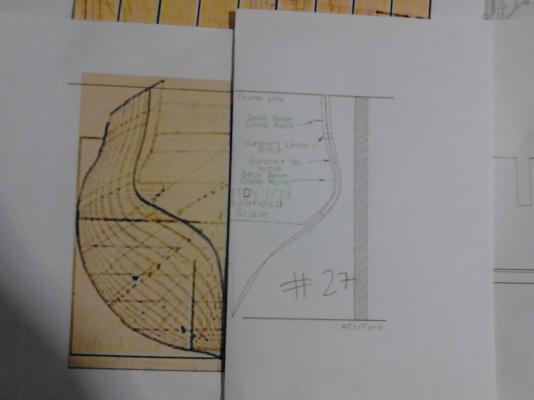
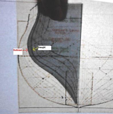
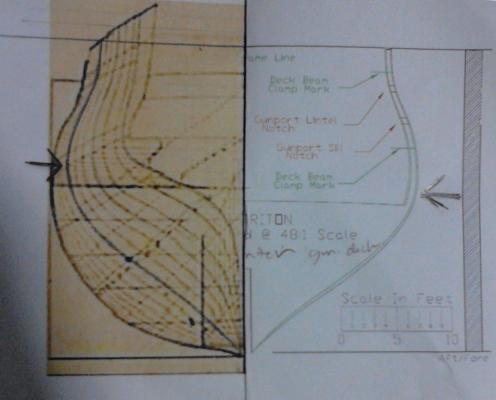
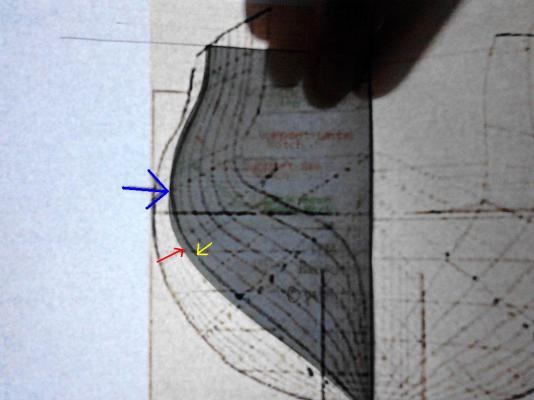
Thank you very much for the kind words, Christian and Fam, I appreciate it Fam, before answering your questions, let me first clarify that these modifications are just based on my very limited understanding of nautical matters and only serve as an alternative approach to building this ship. The provided plans are more than enough to produce a beautiful model, and I just decided to do things a bit differently. Furthermore, let me add a disclaimer that my draughts were purchased way back when NMM allowed us to choose the level of resolution that we will buy, and being the cheapskate that I am, I bought the smallest sized plans, which of course would give fairly limited details. The plans I am using are about the same size as this HMS Pegasus draught that I got at about the same time: I have purchased a much higher resolution "as built" profile/lines drawing of Triton this week, and my modifications may change depending on what I see in this more detailed draught. Now that I've clarified these matters, here are the answers to your questions: Presently no, because I used the inboard profile for the Modified Mermaid Class, which appears to have the least amount of distortion, for my profile comparison. As such, the bowsprit height provided in that profile may not be specific for Triton. As previously stated I purchased a high resolution as built draught of Triton and it is this that I will use for getting the bowsprit height since this is more specific to her. Yes, the bulkheads were compared to the plans, but like I said before, my current plans don't have a very high resolution and thus my work may undergo further modification once I get my hands on the high resolution plans. Did you find if the error is here or there? Might you provide a comparison of the new re-drawn profiles with those provided for the community built? Thank you so much Fam I took some pics with my phone to illustrate my answers here (sorry for the pic quality) Comparison of the POB plans with the draught posed quite a challenge as not all the bulkheads corresponded to a particular station (see below): As seen above only the aftmost stations numbered 1, 4, and 7 corresponded with bulkheads 27, 21 and 15 respectively so comparison was only possible among these. Here are the comparison results: 1. Bulkhead 27 versus 1st aftmost station: the discrepancy is pretty clear here. 2. Bulkhead 21 versus 4th aftmost station: the discrepancy does not seem very pronounced. BUT juxtaposing the bulkhead with the station shows the discrepancy more clearly: 3. The same was true for Bulkhead 15 versus aftmost station number 7: So, based on the pics above, it would appear that the bulkheads 15, 21 and 27 are not very consistent with the stations corresponding to them. Of course, changing these three bulkheads to correspond to their respective stations would also require modifications of the bulkheads in between them (bulkheads 18 and 24). So far, this is only what I've accomplished with this primitive little experiment. I do have a very encouraging finding: As you go towards the waist, the discrepancy becomes less and I've noted that the middle-most bulkhead in the provided plans and the middle-most station in the draught (bulkhead/station 0) are spot on to one another, thus giving me hope that majority of the bulkheads at the waist are faithful to the draught I have yet to work on the other bulkheads and of course, my bulkheads are still open to further changes based on what I see in the high resolution plans, as well as additional feedback/tips/corrections that you, or our other members may provide One thing is sure, I really have to learn CAD as doing these corrections manually is starting to feel a bit tedious

-
Thanks for dropping by, as well as the vote of confidence, Eric, this is actually more of the "gray side" as I'll probably be adapting kit parts for most of my fittings/guns Of course I will never get tired of visiting you guys, I draw my inspiration from your beautiful builds my friend