HOLIDAY DONATION DRIVE - SUPPORT MSW - DO YOUR PART TO KEEP THIS GREAT FORUM GOING! (Only 13 donations so far - C'mon guys!)
×

tlevine
-
Posts
2,032 -
Joined
-
Last visited
Content Type
Profiles
Forums
Gallery
Events
Everything posted by tlevine
-
 To post pictures take a look at these instructions posted by Dan Vadas. http://modelshipworld.com/index.php/topic/540-how-to-add-pictures-in-your-posts-and-pms/. Can you take a picture of the areas of the plan you are questioning?
 -
Files are a lot like clamps...you can never have enough of them. My selection ranges in size from round and flat files with the word Craftsman on them all the way down to various shapes of Grobet jeweler's files. Until you develop your preferences and decide how fine or coarse a file you want (and how much you want to spend), it is hard to beat various shapes and grits of sanding sticks. If you use a repositionable glue stick, the sandpaper is easily replaced when it is worn.
-
Frame construction
tlevine replied to jbeyl's topic in Building, Framing, Planking and plating a ships hull and deck
The beauty of a Google search is that it is free. And sometimes it even provides you with answers from individuals qualified to have an opinion. If you are interested in building a fully framed model, I would recommend developing your library first. Get the first two volumes of TFFM. Get Ed Tosti's volumes on Naiad. Look at prints from the Royal Museum Greenwich which illustrate frame construction throughout the years. Only then should you decide whether you are as crazy as the rest of us Swan-class builders. If the answer is yes then welcome aboard. -
Kevin, very nice build. Please check the locations of the timberheads against the as-built plans for Thorn. The locations for a few of the timberheads on Atalanta (and Fly, the only other vessel I have plans for) differ from David's Mylar plan. It would be easy to correct now if necessary. For example, on the plan you show in your video, the two of the timberheads are made of short stuff above the last gun port. On Atalanta the timberheads were shifted to prevent this.
-
I would doubt it because when I bought it from the vendor there were two models available, one for the Dremel and the other for the MicroMark. I am sure the thickness and length of the table is different on the two saws.
-
Dave, I think a bending chart would be a great addition. I am surprised so many builders use swiss pear rather than natural pear. IMHO the color is too pink and the working characteristics are not as nice.
-
It is called the Accurizer II and I have the same thing for my Dremel. It also came with a cross-piece for the back of the saw to stabilize the motor. I think it is still available for the MicroMark saw. Using this, the zero clearance plates and the toothed belt you have a very accurate machine powerful enough to rip 1/2" stock without any problem. If only the fence was taller...
-
Kurt, in the photo from left to right are #12, #15 and #11 blades. The drop-off angle on the non-cutting side varies by manufacturer. The #12 is also called a tonsil blade (you can guess why).
-
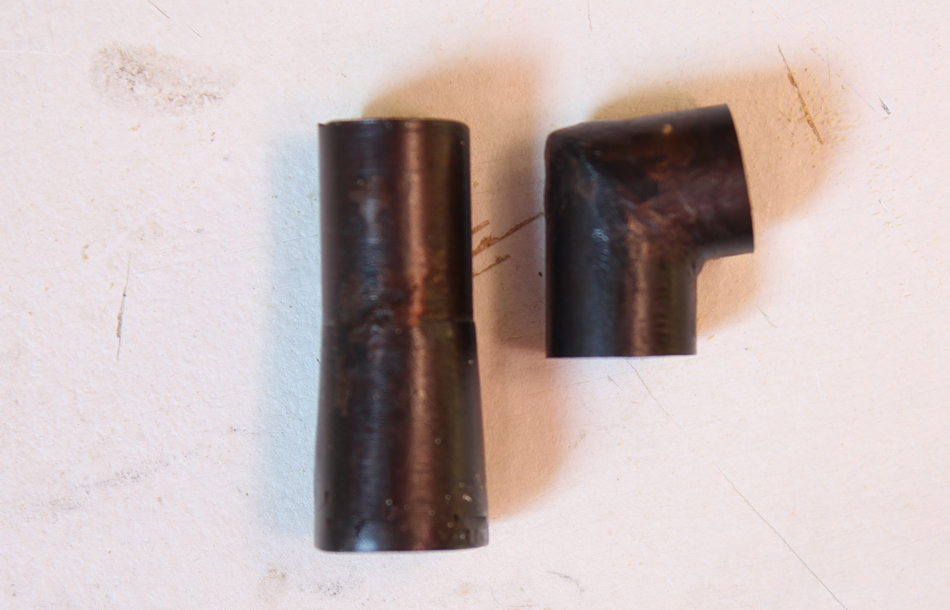
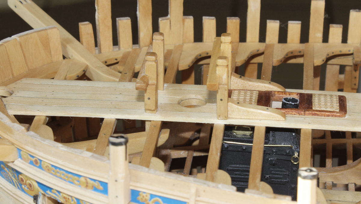
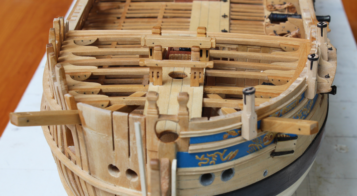
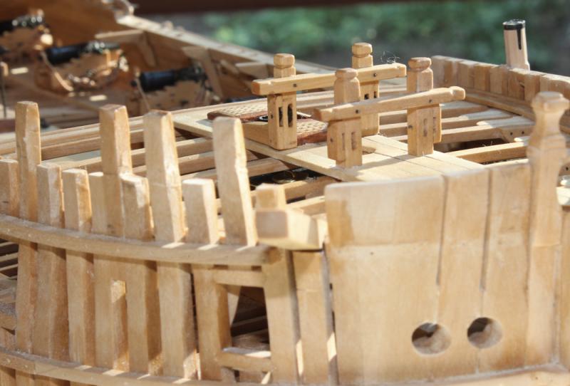
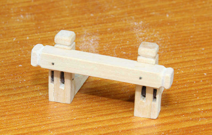
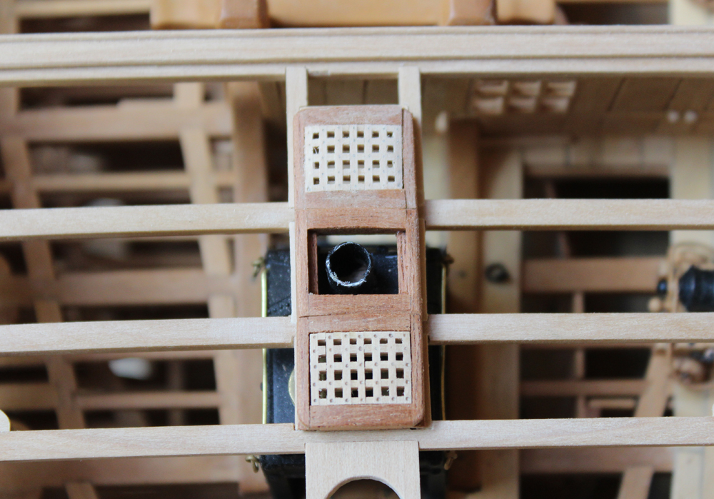
As mentioned above, I rebuilt the jeer bitts and crosspiece. Again, thanks to Dave for pointing it out. The only reason I can think of for the glaring mistake is a total brain shutdown. Forgive the Qtip fuzz on the crosspiece... It's gone now. The stove flue is comprised of two sections. The lower section is conical and the upper is cylindrical. On most of the Swan class ships there is an angled piece with a baffle. On Atalanta and Fly the flue is straight. While I was waiting for Druxey's affirmation, I made up both types of ends for the stove flue, straight and angled. The conical section is made by cutting a v-shaped slit in an oversize brass tube. The tube was heated to remove the temper and slit was closed, resulting in a conical shape. This was then silver soldered and the top and bottom were cut off for the correct length. The upper and lower sections were then soldered together and the piece was blackened and coated with Floquil dull finish. I still need to make a metal plate for the coaming. Druxey, maybe the captain "borrowed" the flue from Pegasus after enough rain ran down into the stove!


-
I am getting ready to construct the flue for the stove. On the plan (kindly provided by Dave 2 posts above) the flue is shown as straight. I checked out several other of the Swan class ships and the only other one I could find with this convention is Fly. My question is did the artist simply not draw the flue correctly since this was provided by an outside vendor or was the flue truly straight? Any guidance would be appreciated. I also rebuilt the jeer bitts and crosspiece. Pictures pending. It looks much better now.
-
Experiment on some scrap to see what brand appeals to you. But since you used a Sharpie, it should be an acrylic finish to prevent bleeding.
-
What are you planning to use as a finish? Any solvent based finish will cause the Sharpie to bleed into the surrounding wood. (I found that lesson out the hard way.) That is why many of us use a pencil lead, paper or paint.
-
Well, sir, I concur with you. It also appears my fore topsail sheet crosspiece may be too small. I guess I have my project for next weekend. Thank you for pointing this out.
-
Thanks everyone for the likes and comments. Dave, I measured the dimensions directly off the Admiralty plans. As I mentioned, Atalanta's fore jeer bitt was different from some of the other Swan class ships. What struck me is how something this large is only bolted onto two flimsy forecastle beams.
-
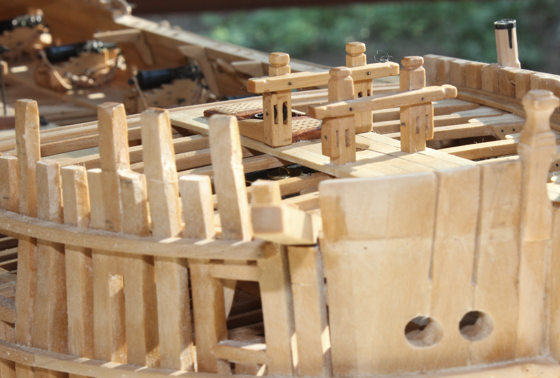
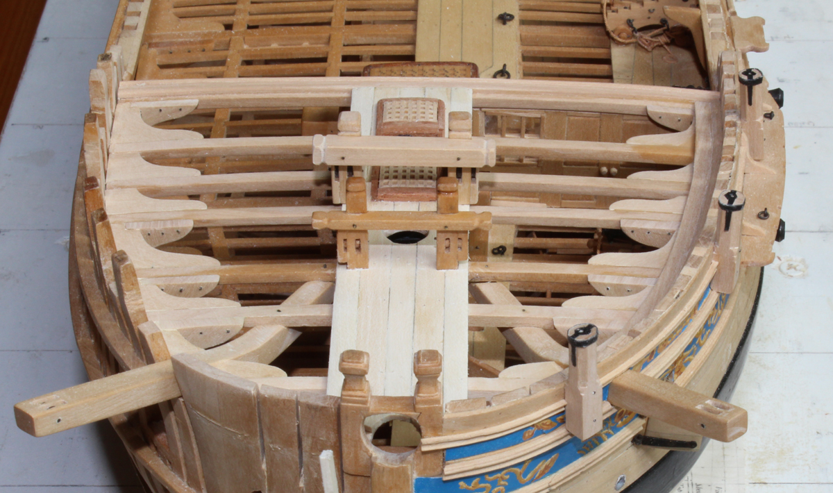
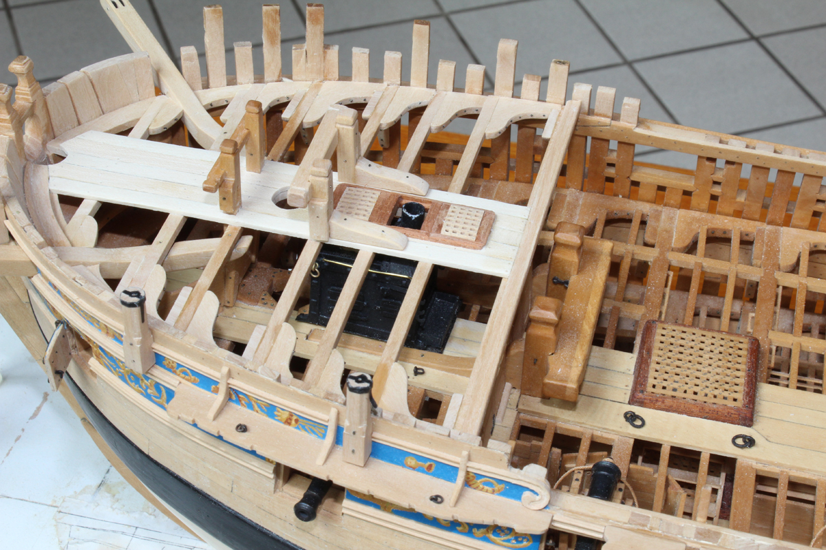
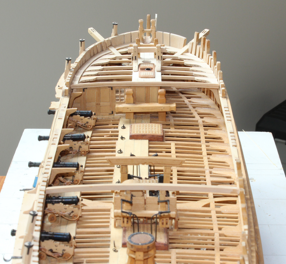
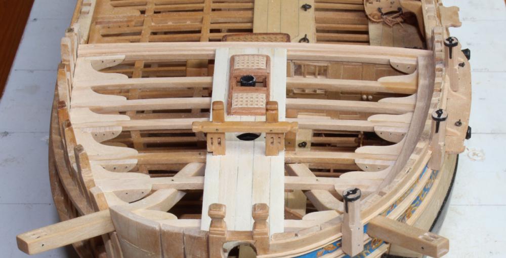
The next decision was how much planking to show on the forecastle. I decided on sufficient planking to support the fore jeer bitts, leaving the rest of the deck unplanked. The planks run the entire length of the forecastle deck, tapering slightly stern to bow. The fore jeer bitts are bolted onto the deck. The location varied among the different Swannies. On Atalanta, the crosspiece is on the fore side of the standards and there is only a 9" gap between it and the foremast. On Fly, the crosspiece is on the aft side of the standard. On Vulture, Dan Vadas states there are no standard because of the width of the hatches. The standards are bored for a 7" diameter sheave. There is also a cheek block with another 7" sheave, similar to the fore topsail sheet. Since the next step is adding the eyebolts at the foot of the foremast, I decided to apply the wood finish to the forecastle structure and fore jeer bitts. It is amazing what a difference that makes.


-
Druxey and Greg, thanks for looking in. Also, thanks for the likes. Geoff, maybe next time. But nothing is stopping you from putting them on your build! Three sets aren't that many Martin. And yes they are cherry. I wanted just a little color contrast on deck.
-
Tools and Supplies for My "Shipyard"
tlevine replied to daveward's topic in Modeling tools and Workshop Equipment
Regarding 11 blades... The brand of scalpel blades is not important. For our purposes, any brand will work fine. They cannot be resharpened. Personally, I prefer free blades that I put onto a "proper" scalpel handle. I hate using the plastic handles in surgery and I hate using them for my models. They do not hold the blade as securely as a metal handle and they flex. I use a long handle (#7) because I can see over my hand while I am using it. Image below borrowed from Havalon tools (I have never used them, it was simply a nice picture). -
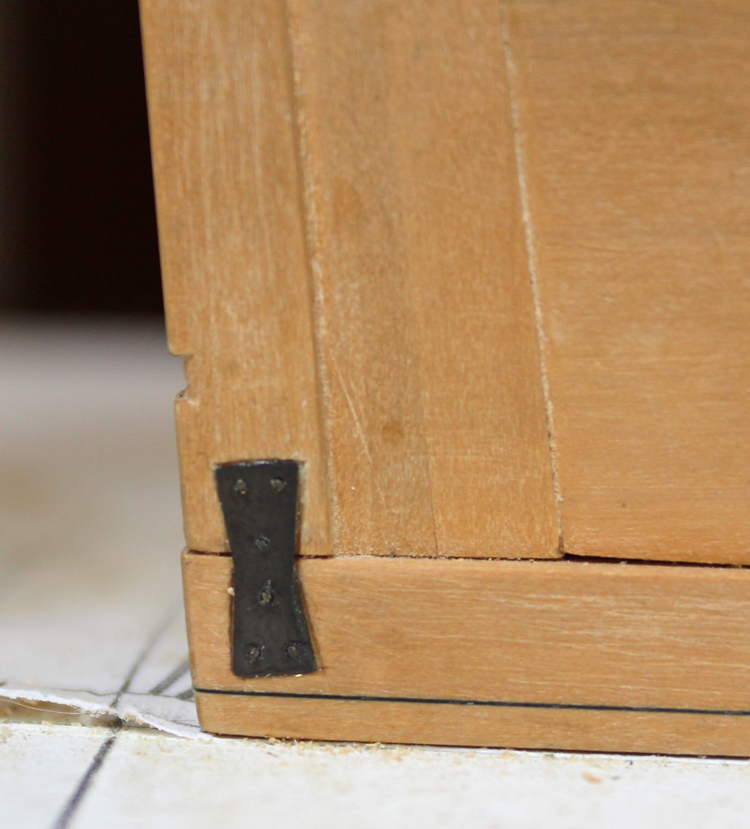
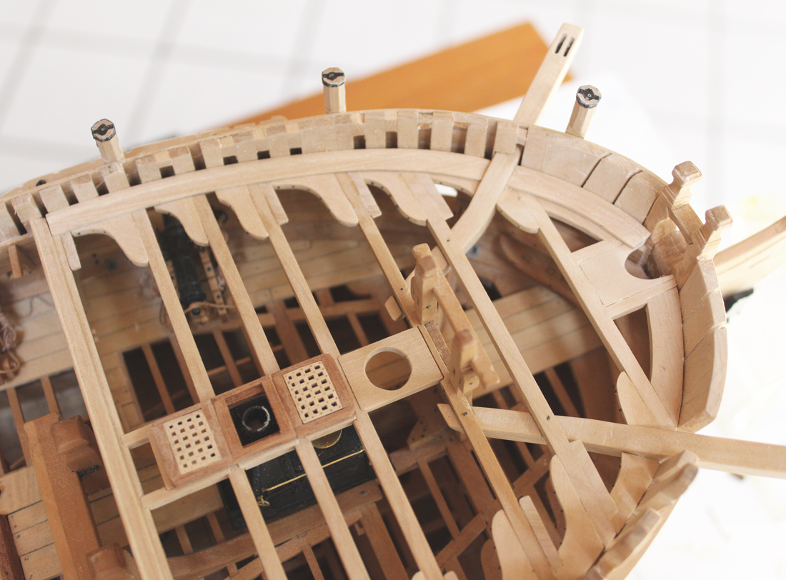
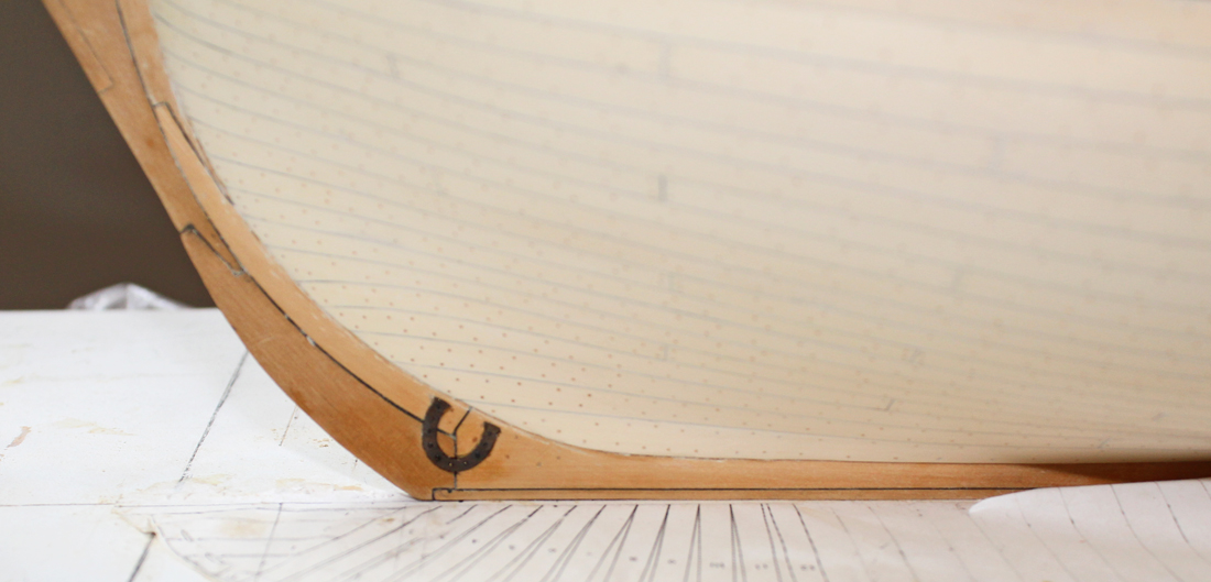
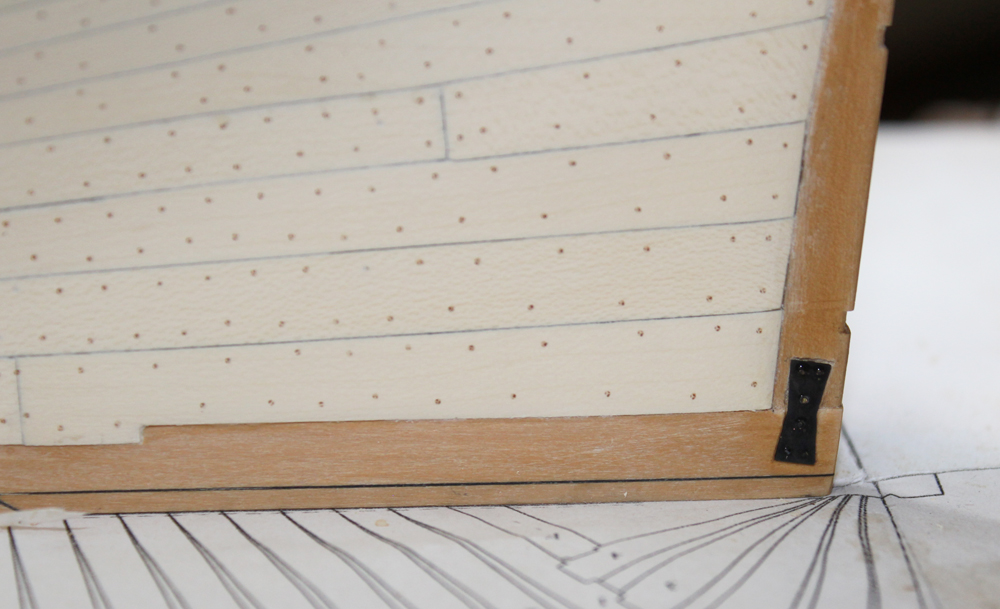
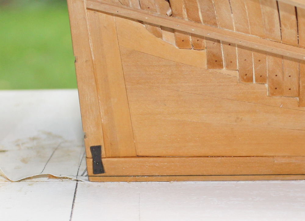
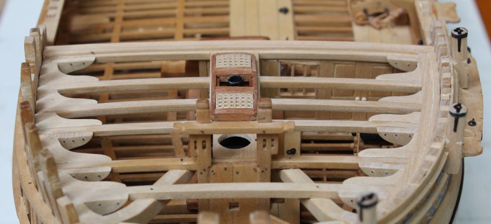
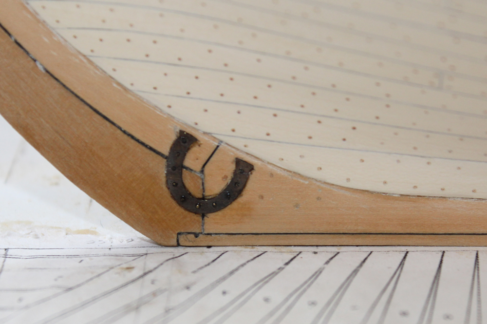
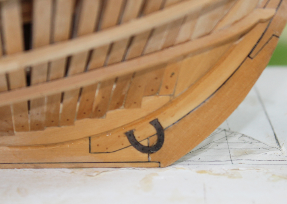
It has been a while since my last postings. Summer is always very busy and leaves little time for modeling. I built the forecastle hatch coamings and gratings. These are made like the ones on the upper deck except the scantlings are all smaller. When making hatch coamings, it it much easier to build the grating first and make the hatch fit the grating. Needless to say I made two sets of hatches. Before there was any more detail to knock loose, I decided to apply the horseshoes and dovetail plates. These are from Greg's photoetch set. They were cut off the sprue and their outline was drawn onto the hull. Using an 11 blade, I make a light impression just inside the pencilled outline. Then I cut away the inner area with a 3mm chisel. The bolts are blackened brass wire. I enlarged the holes in the plates to a 75 drill bit to accomodate the wire. The plates were then epoxied to the hull. I will be applying minimal planking to the forecastle deck. The waterway was made by taking a template of the outline of the bulwark and then cutting out a piece of costello to fit. The rebate was hand cut.


-
Great to see another Washington build. Mike's idea of two blind holes after beveling is great.
-
Consider slitting saw blades. They come in various thicknesses to match the thickness of your grating. Here are two companies I have purchased from in the past. http://www.thurstonmfg.com/and http://www.malcosaw.com/ I think you can also pick them up on EBay. Be sure you specify the correct diameter and center hole size.
- 553 replies
-
- 2
-

-
- sloop of war
- constellation
- (and 3 more)
-
Please remember that this is a recreation of a Spanish galley. It is not meant to represent any single vessel. Considering this ship is built of fiberglass with wood lamination, I would recommend independent validation of any details.
- 962 replies
-
- 5
-
-
- sovereign of the seas
- ship of the line
- (and 1 more)
-
Beautiful hull, Gary. I agree with you 100% on the spacers as I made the same mistake on Atalanta.
-
Let's see Chuck...college four years, medical school four more years. At least when she starts residency, they pay her instead of the other way around!
- 1,051 replies
-
- 7
-
-
- cheerful
- Syren Ship Model Company
- (and 1 more)
-
whats an easier build for a first kit
tlevine replied to rdestefano01's topic in Wood ship model kits
Kurt, I would call it your tradition! As long as the women don't need to wear hula skirts...