


Timmo
-
Posts
609 -
Joined
-
Last visited
Content Type
Profiles
Forums
Gallery
Events
Posts posted by Timmo
-
-
Nice boat Christian. I've been waiting for the return of your Diana. Welcome back.
-
Thanks mike.
Full rudder installation is a long way off so I might revisit it.
I tested one with a bit of pressure and it took quite some force to snap the joint so I figured with the load spread across five pintles it should be ok.
- Omega1234, mtaylor, mikegerber and 1 other
-
 4
4
-
Hi mike. It's soft solder on those joints.
- Omega1234, mtaylor and mikegerber
-
3
-
-
I wanted to sort the rudder mounting before moving much further as I've still got the stern post unattached.
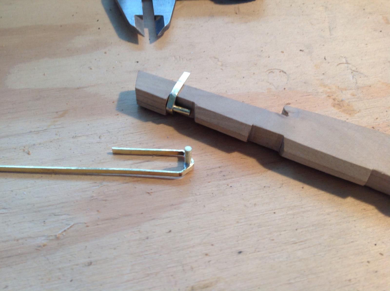
I was thinking of a simplified rudder mounting with a top and bottom rod and tube but after a bit of experimentation I'll try the sort of gudgeon and pintle arrangement on the original and if it doesn't work simplify from there.
The key would seem to be getting the rod and tube making the hinge to sit squarely so a jig was knocked up from timber the same width as the rudder and stern with a just-under 1mm strip glued down the centre to allow a tolerance for the width of the brass strip.
The rudder has also been beveled on the forward edge to allow for a decent 45 degree turn.
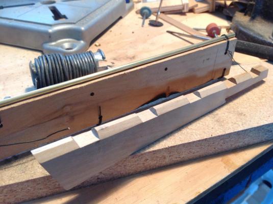
The rod was wired down to the jig and the brass strip bent to shape and laid over top and clamped down nice and square for soldering.
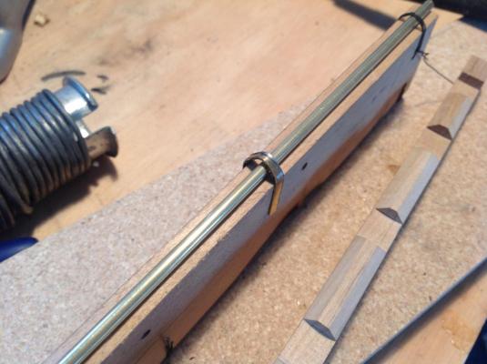
I was quite pleased with my first attempt soldering anything bigger than stereo wiring. A butane torch was used to flow the solder into the joint. The rod/tube was cut free when set and the resulting piece cleaned up with a file.

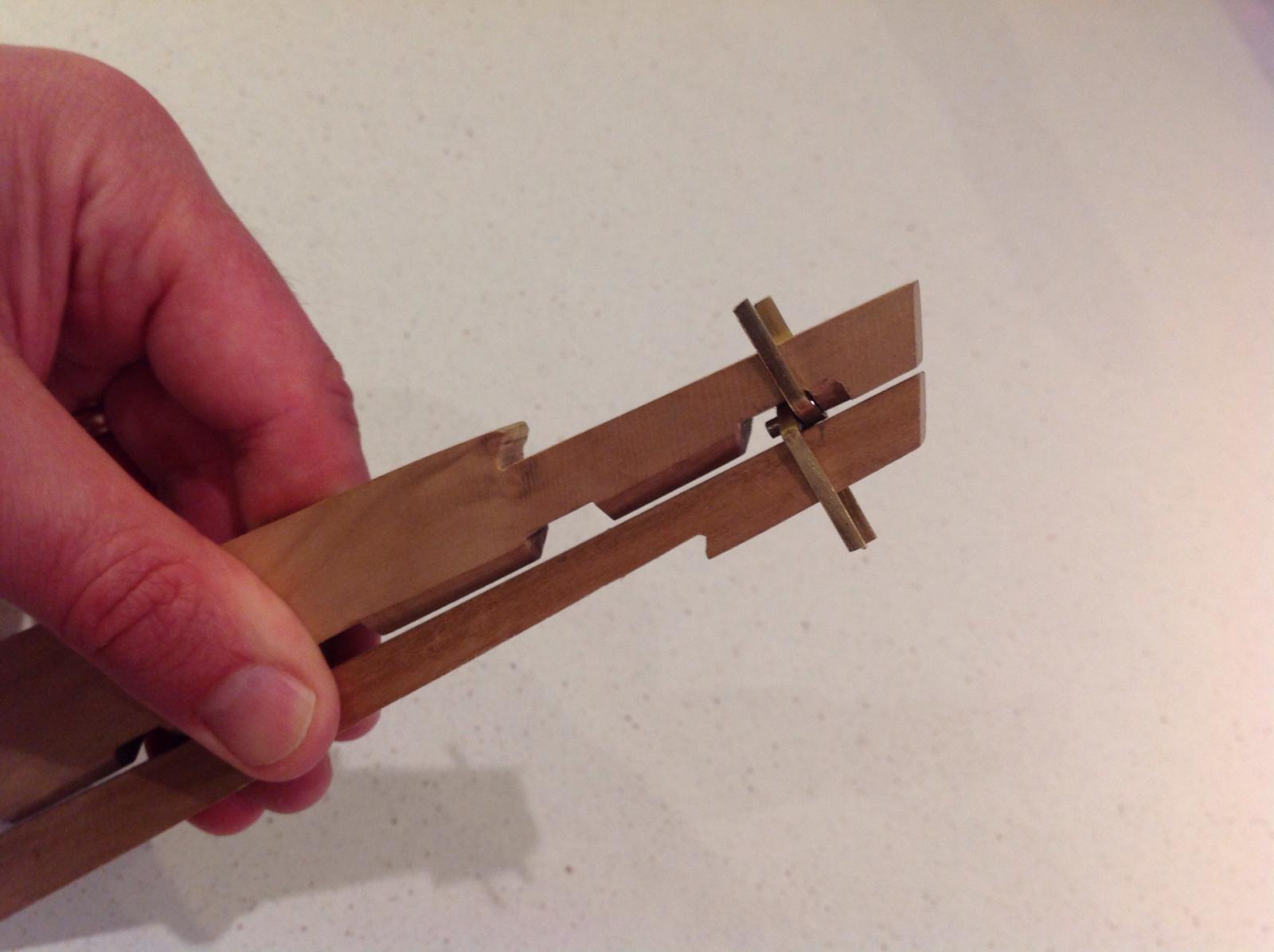
That's a couple done and it provides a nice strong, yet free moving joint.
The only concern is there might be too little tolerance in the tight fitting tube and rod to account for my inaccurate squaring and soldering but I'll keep going and see how it turns out.

- avsjerome2003, Canute, Dubz and 14 others
-
17
-
-
You'll never regret a rework Jason. Nice tidy fix there.
-
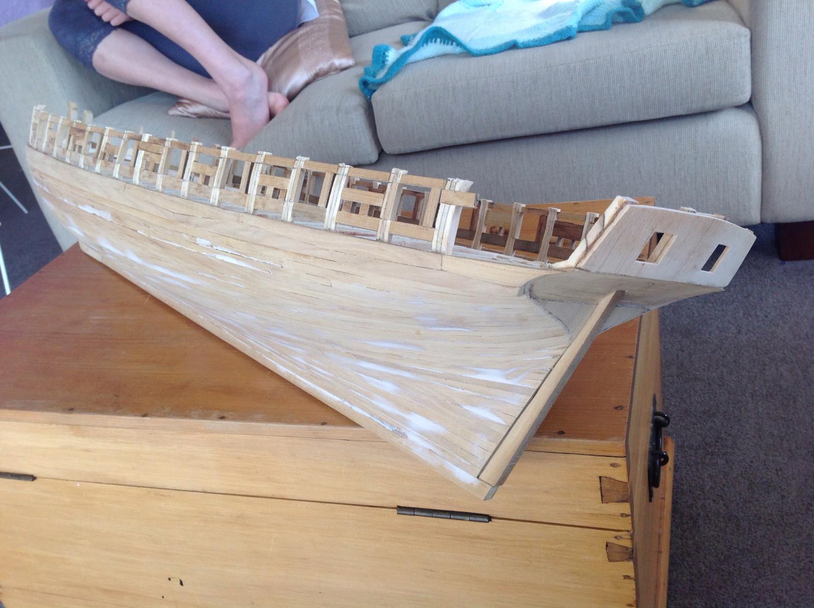
The bow section of the the bulwark framing is complete. It was cut from the deck plan on a bandsaw and sanded to fit. Upright supports were added and the whole lot epoxied in place.
.
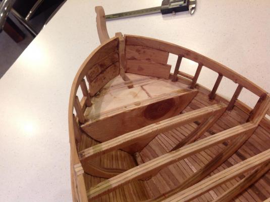
The bulwarks where the hawse holes will be were filled in to provide a solid section to drill through. It's a bit rough on the inside but it'll all be covered with planking. Nice to see the full sheer line now.
The rudder slot is roughed out to test the fit. I'll have to sort out the mounting of the rudder with resulting functional pintles and gudgeons before much further progress. The rudder will likely be mounted with a brass plate and screw/pin from the keel at the foot of the rudder for stability.
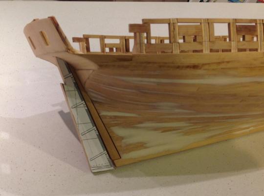
The final piece of bulwark railing at rear will be added once the inside of the stern counter is filled out and tidied.
- _SalD_, PeteB, Mirabell61 and 13 others
-
16
-
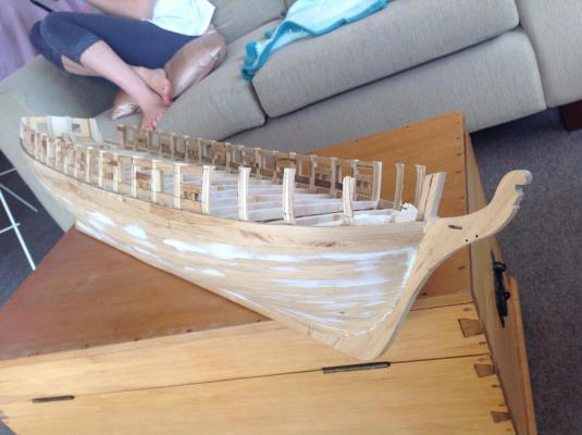
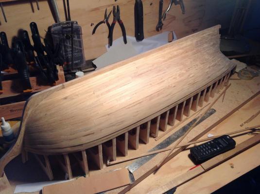
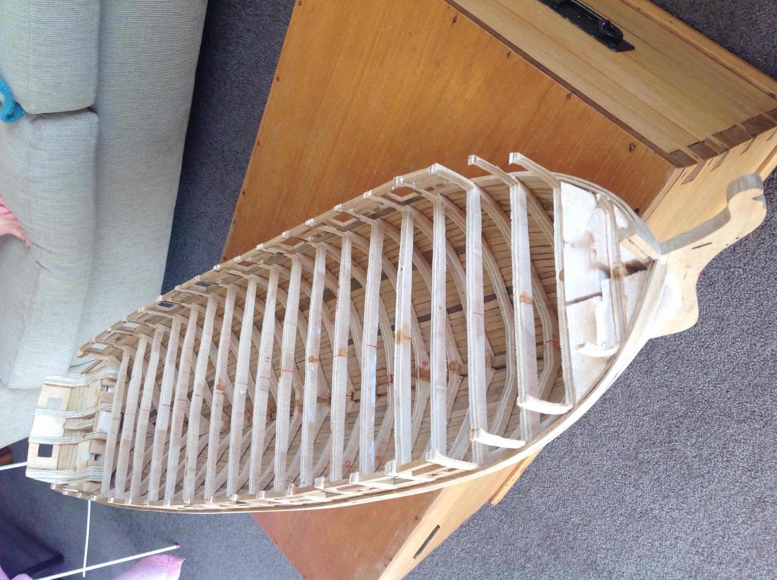
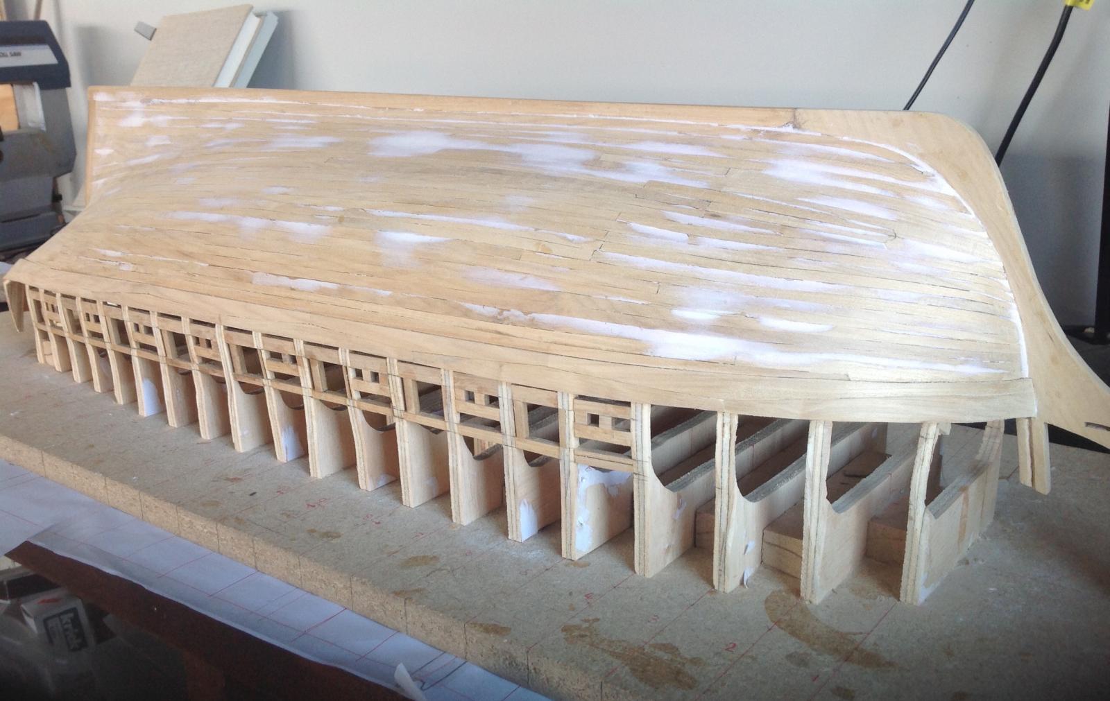
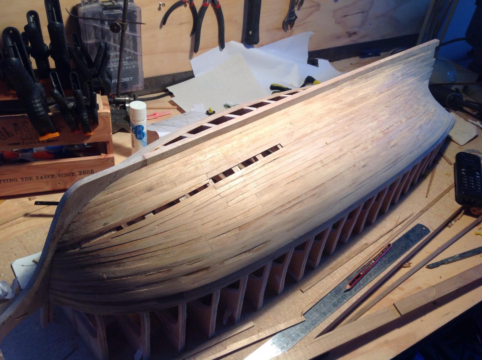
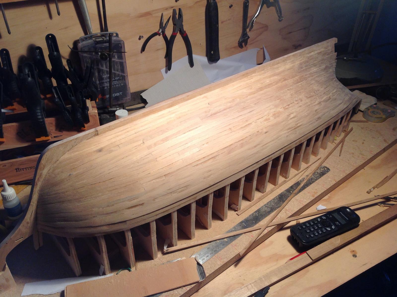
The cruizer has been cut free from its building board. It's surprisingly light but feels fairly strong and fibreglass will still be needed.
Framing for the bow and stern bulwarks next.
I'm liking those lines and think in hindsight I probably should have gone for a slightly larger scale. I'm sure it'll be fine.


-
-
-
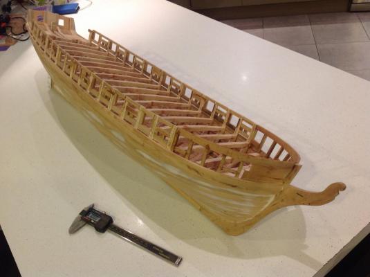
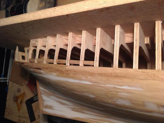
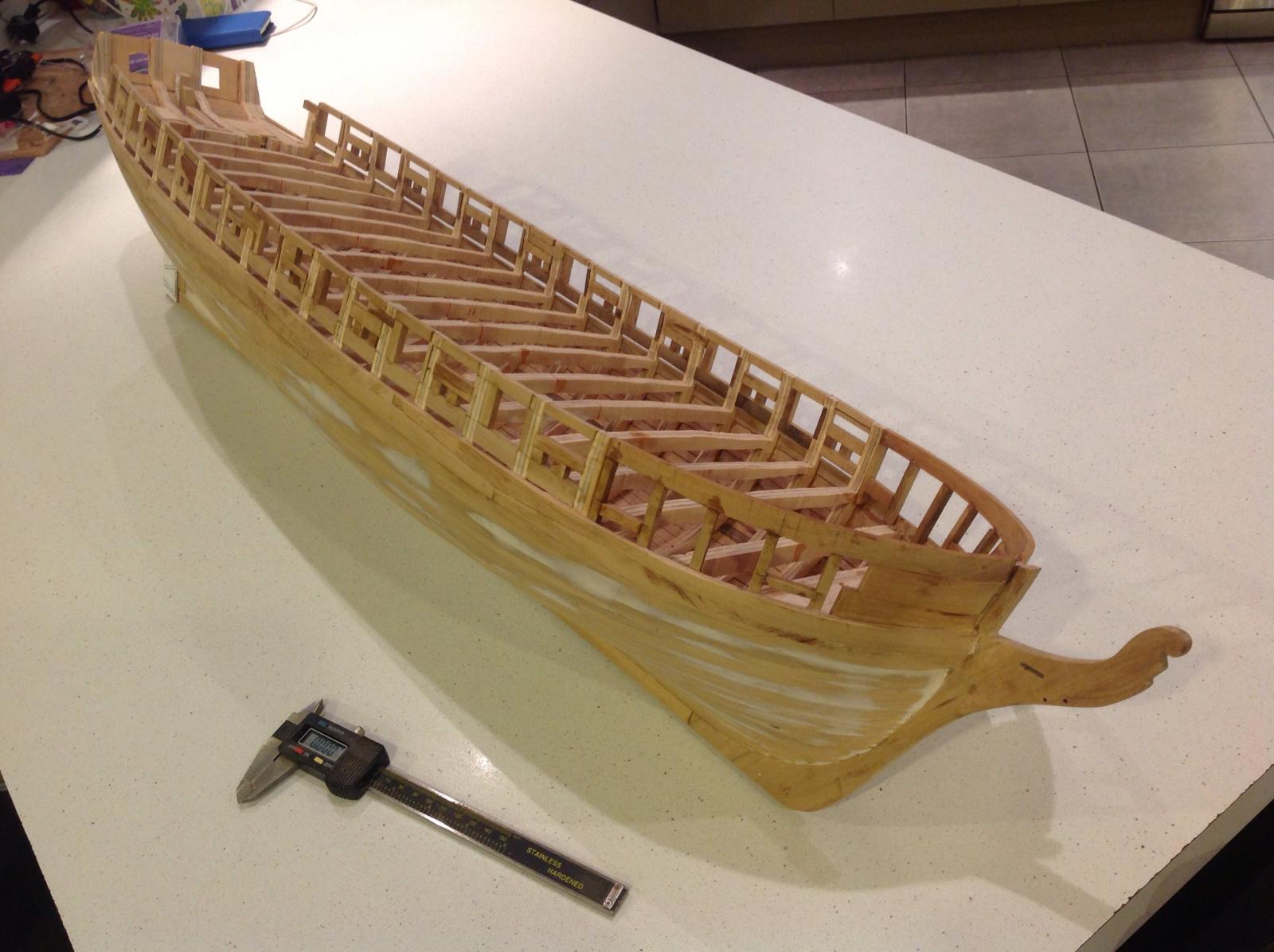
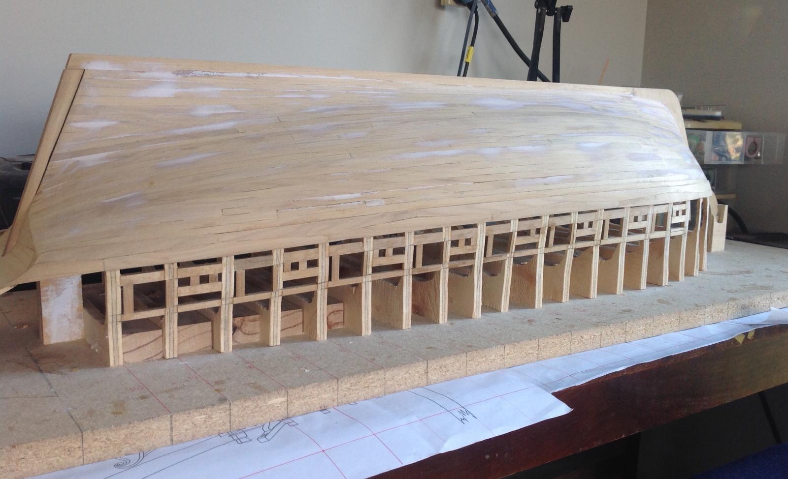
The boxing for the bulwarks and frames outlining gun and sweep ports is underway. The framing is 4.5mm timber which should be fairly strong by the time it is planked on both sides and glassed.

The cruizer will be cut free from its board once the central sections of both sides are framed and rigid. This will give better access to the bow section with its curved bulwark.

- tadheus, _SalD_, avsjerome2003 and 13 others
-
16
-
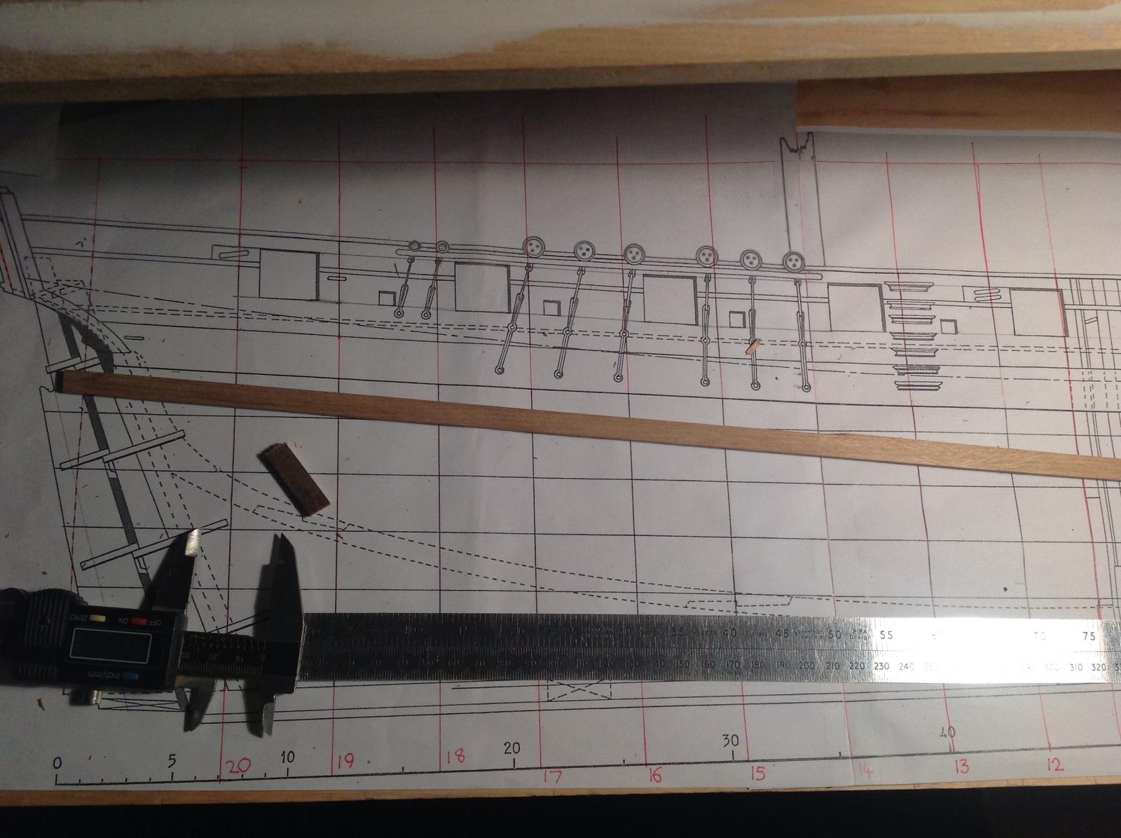
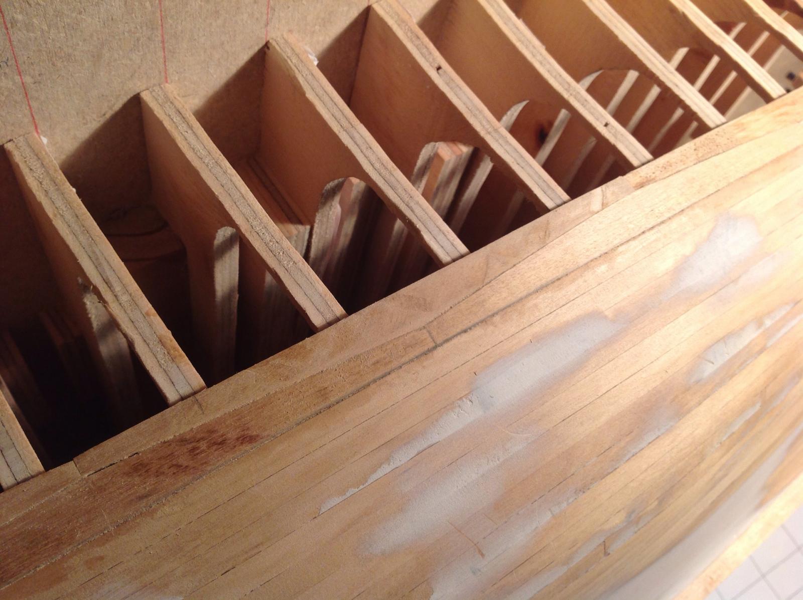
The first gunport sills have been placed. Timber 4mm in width is being used here and will also provide the lower sills for the sweep ports.
You can also see some rough filling here. It'll be tidied up later.
The level of the sills is measured from the red base line at top drawn on the plans which corresponds with the level of the building board. A plank is pushed against the sills and frames from the outer hull to get them flush with where the hull planking above the wales will eventually sit.
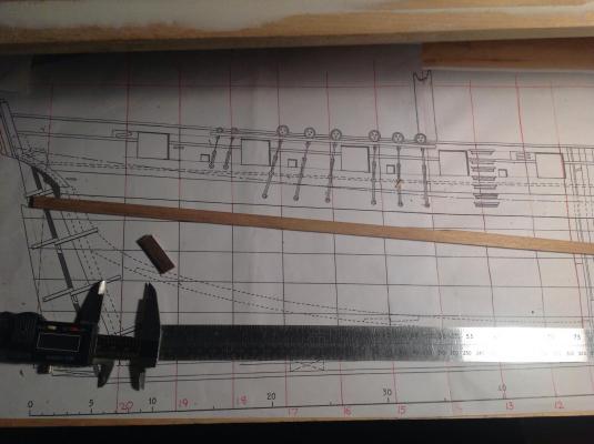
The wales have also been finished using an anchor stock pattern on the final layer to bring them to thickness. They are as yet unsanded.

-
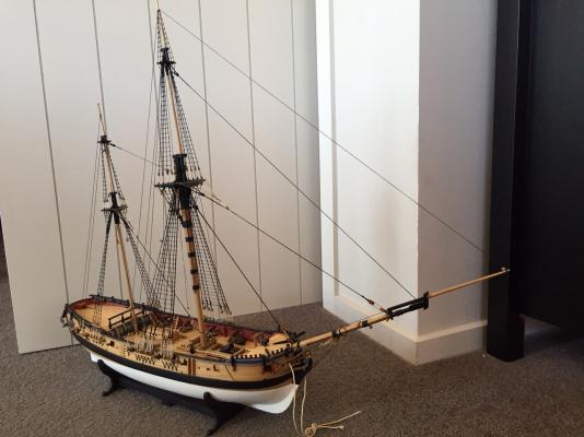
A bit of switching between my cruiser project and back to Granado as it gets too cold to work in the garage has resulted in Granado having her standing rigging finished.
Also the very first of the spars is on with the wingsail gaff fitted.
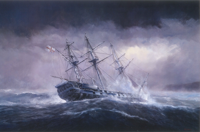
Also, I've posted this elsewhere but those with a bent for nautical history might like a story I've done on a local shipwreck - the demise of HMS Buffalo.

Image: Paul Deacon
- Captain Slog, egkb, Beef Wellington and 5 others
-
8
-
Been a bit busy lately mixing work with pleasure.
Here's the result - A story of shipwreck drama featuring HMS Buffalo

Image: Paul Deacon
- PeteB, aviaamator, Omega1234 and 2 others
-
5
-
-
Hi Eric,
I'm looking forward to following this build. I do like an Agamemnon.
I think you're the closest ship modeller to me I've discovered on MSW.
Wayne
-
Satisfying moment with one side completed. I abandoned the very tidy planking plan and went for speed, hence the strange shape of the last plank.

Finished.
The other side has a few left to finish then a bit of filling and sanding.
-
Top work Bob. Congratulations on a quality build.
-
-
The cast guns were pretty rough but they did clean up with some filling, filing and lots of sanding. I doubt I'd go to such effort again and would likely replace.
-
-
-


Cruizer-class brig by Timmo - FINISHED - 1:36 scale - RADIO
in - Build logs for subjects built 1751 - 1800
Posted
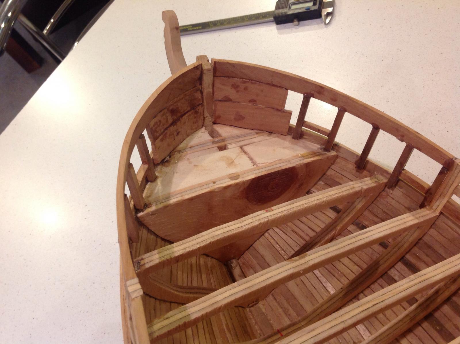
The bulwarks are now fully planked, giving the shape of the completed hull.
The first 'mechanical' piece has also been added in the form of a brass tube to carry the tackle for the spanner boom. It exits through the taffrail and was shaped to fit around the chase ports and flow into the hull cavity.
It's not strictly accurate having the boom belayed to the centre of the taffrail but it's one less hole in the deck where water ingress is more likely and also avoids the potential of fouling the steering gear and lines once the tiller is on the rudder head.
Although it's sanded fairly smooth I'll plank the inside of the rear counter to avoid any texture issues.