shipmodel
-
Posts
941 -
Joined
-
Last visited
8 Followers


About shipmodel

Recent Profile Visitors
5,147 profile views


-
 shipmodel reacted to a post in a topic:
La Créole 1827 by archjofo - Scale 1/48 - French corvette
shipmodel reacted to a post in a topic:
La Créole 1827 by archjofo - Scale 1/48 - French corvette
-
FreekS reacted to a post in a topic:
The Khufu solar barge c. 2566 BCE by shipmodel (Dan Pariser) - scale 1:10 - cross-section
-
FreekS reacted to a post in a topic:
The Khufu solar barge c. 2566 BCE by shipmodel (Dan Pariser) - scale 1:10 - cross-section
-
FreekS reacted to a post in a topic:
USS/SS Leviathan 1914 by shipmodel - FINISHED - 1/200 - troop ship/ocean liner
-
shipmodel reacted to a post in a topic:
Soleil Royal by Hubac's Historian - Heller - An Extensive Modification and Partial Scratch-Build
-
shipmodel reacted to a post in a topic:
Soleil Royal by Hubac's Historian - Heller - An Extensive Modification and Partial Scratch-Build
-
GrandpaPhil reacted to a post in a topic:
Soleil Royal by Hubac's Historian - Heller - An Extensive Modification and Partial Scratch-Build
-
 Hubac's Historian reacted to a post in a topic:
Soleil Royal by Hubac's Historian - Heller - An Extensive Modification and Partial Scratch-Build
Hubac's Historian reacted to a post in a topic:
Soleil Royal by Hubac's Historian - Heller - An Extensive Modification and Partial Scratch-Build
-
shipmodel reacted to a post in a topic:
Soleil Royal by Hubac's Historian - Heller - An Extensive Modification and Partial Scratch-Build
-
 Marc - I agree completely with the sentiments, but would change the terminology a bit. For me, it is not 'patience', which is waiting for something to happen, but 'perseverance', which is working steadily through the ups and downs of the process, and enjoying the journey along the way. Dan
- 2,699 replies
-
- 2
-
-
-
- heller
- soleil royal
- (and 9 more)
-
shipmodel reacted to a post in a topic:
Soleil Royal by Hubac's Historian - Heller - An Extensive Modification and Partial Scratch-Build
-
shipmodel reacted to a post in a topic:
Soleil Royal by Hubac's Historian - Heller - An Extensive Modification and Partial Scratch-Build
-
Ryland Craze reacted to a post in a topic:
Mary Day by jdbondy - 1:64 scale (3/16" to 1 foot) - Schooner
-
Keith Black reacted to a post in a topic:
Mary Day by jdbondy - 1:64 scale (3/16" to 1 foot) - Schooner
-
Beautiful work, JD Dan
-
shipmodel reacted to a post in a topic:
Mary Day by jdbondy - 1:64 scale (3/16" to 1 foot) - Schooner
-
shipmodel reacted to a post in a topic:
Mary Day by jdbondy - 1:64 scale (3/16" to 1 foot) - Schooner
-
EJ_L reacted to a post in a topic:
Soleil Royal by Hubac's Historian - Heller - An Extensive Modification and Partial Scratch-Build
-
druxey reacted to a post in a topic:
Soleil Royal by Hubac's Historian - Heller - An Extensive Modification and Partial Scratch-Build
-
Hubac's Historian reacted to a post in a topic:
Soleil Royal by Hubac's Historian - Heller - An Extensive Modification and Partial Scratch-Build
-
As always, a great illustration of the powers of observation, innovation, and persistence. Bravo. Dan
- 2,699 replies
-
- 3
-
-
-
- heller
- soleil royal
- (and 9 more)
-
shipmodel reacted to a post in a topic:
Soleil Royal by Hubac's Historian - Heller - An Extensive Modification and Partial Scratch-Build
-
At 75 I have survived all of the transformations that I care to. I'll be happy if I can walk around the block at a brisk, non-transformational pace. D
- 2,699 replies
-
- 5
-
-

-
- heller
- soleil royal
- (and 9 more)
-
Hi Marc - I finally got fully caught up with your excellent progress after some time away for life matters. Great work on the decorative details. I can only envy your casting and molding success. These are skills that I have never mastered. I agree with your decision on the capstan. As far as I know it was a transitional time for this element and either style would be appropriate, but the earlier style is more 'stylish', IMO. I am scheduled for surgery of my own - knee replacement - in January, so we can compare crutches. Dan
- 2,699 replies
-
- 3
-
-
-
- heller
- soleil royal
- (and 9 more)
-
shipmodel reacted to a post in a topic:
Soleil Royal by Hubac's Historian - Heller - An Extensive Modification and Partial Scratch-Build
-
Cisco - It was great seeing you and your AVS at the show. Your pics here are excellent, but she is even better in person. Very nice work. Thanks also for the compliments. Glad you found that my talk was a bit entertaining and informative. If you decide to do an Admiralty-style hull, feel free to pick my brain. See you in New London next year. Dan
-
Sorry, the picture did not come out last time. I'm trying again. If it doesn't work this time just put the URL into your browser and you should find it. Dan

- 2,699 replies
-
- 6
-
-
-
- heller
- soleil royal
- (and 9 more)
-
Hi again Marc - I am away from my library, but I did an internet search and found this image of an earlier breech block naval cannon. Note the bucket with two linstocks in it to the right of the picture. Dan https://th.bing.com/th/id/OIP.DCqIP8t7t0Um7Df-krV_egAAAA?rs=1&pid=ImgDetMain
- 2,699 replies
-
- 2
-
-
-
- heller
- soleil royal
- (and 9 more)
-
Hi Marc - I agree with Henry that this is a tub for holding the butt end of the linstock staff during action stations. I believe that I read, perhaps in one of the Hornblower or Aubrey/Maturin books, that the top was open and it was filled with sand. You just had to ram the end of the staff into it and it would be held upright. The upside down conic shape has the wider base to prevent tipping over, like using an upside down paper cup on my workbench. I also agree that they are pretty crude as is. I wouldn't use them unless I was fitting out each gun station in detail. If you do, you could scribe some stave joints and barrel rings into them. Dan
- 2,699 replies
-
- 3
-
-
-
- heller
- soleil royal
- (and 9 more)
-
Cisco - Coming along very nicely. Looking forward to seeing you and her in New London. Dan
-
Hi Vossie - After your comment on my current build I went to yours and read your 8 year odyssey. I have to applaud your perseverance and dedication in working through not only the many puzzles that we all have to solve in building a ship model, but in overcoming all the breakages and injuries, both mechanical and personal. She will be a beautiful lady when you are done, and a source of immense and justified pride. Congratulations. Best wishes for a speedy and complete recovery from your latest challenge. Looking forward to following along in the future. Dan
- 714 replies
-
- 2
-
-
- lady nelson
- victory models
- (and 1 more)
-
Hi Druxey. Thanks for the suggestion. I looked at the photo, but there was no description of the item. Is it a 6" plastic strip with a sandpaper type surface? If so I'm sure I can make up something like it for less than $3 each. LOL Dan
-
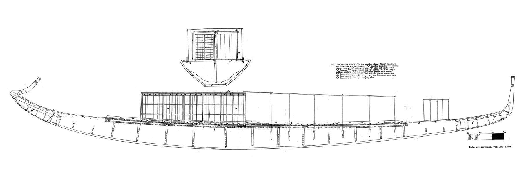
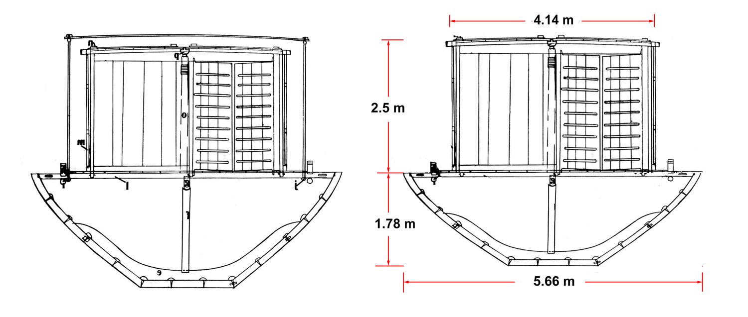
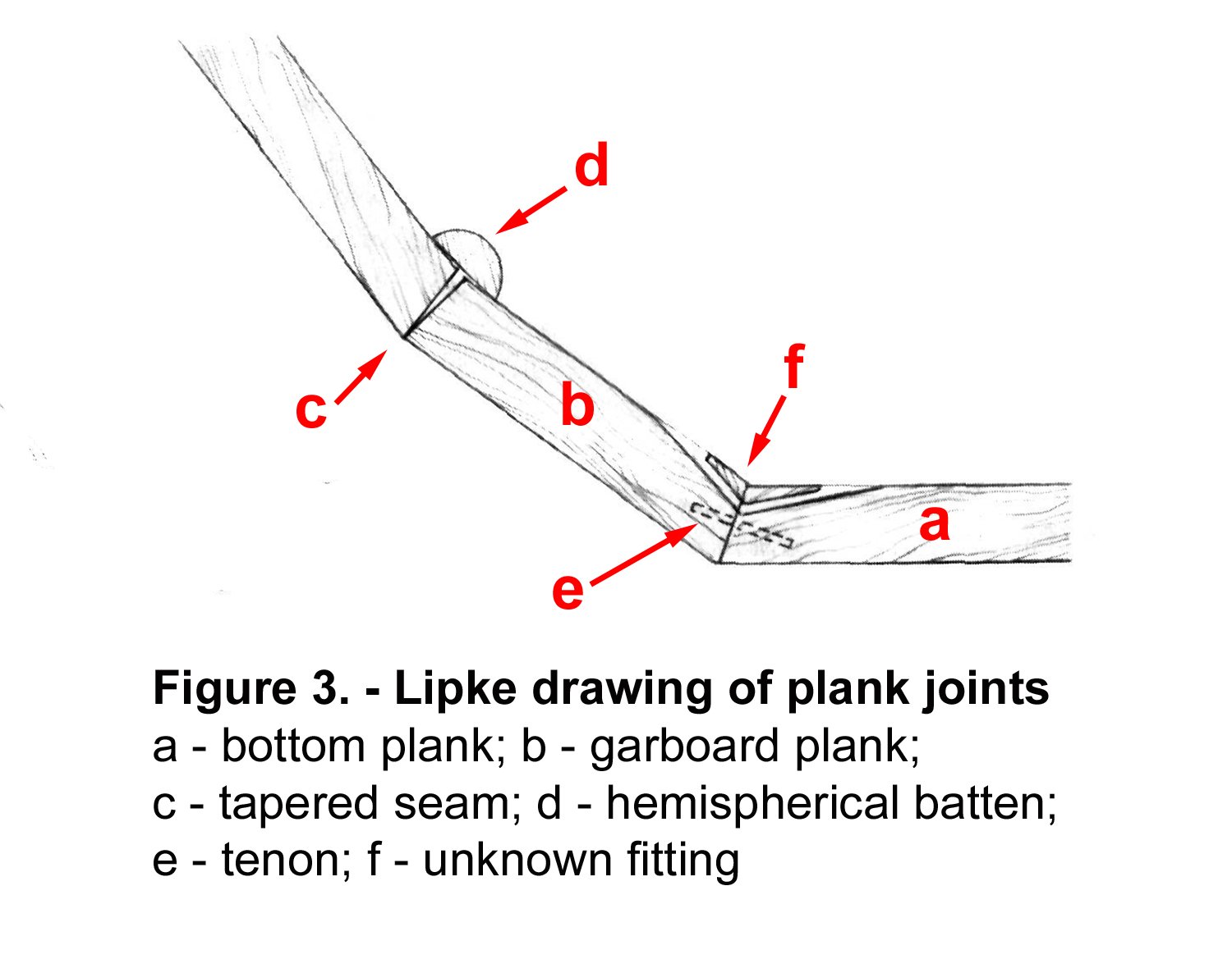
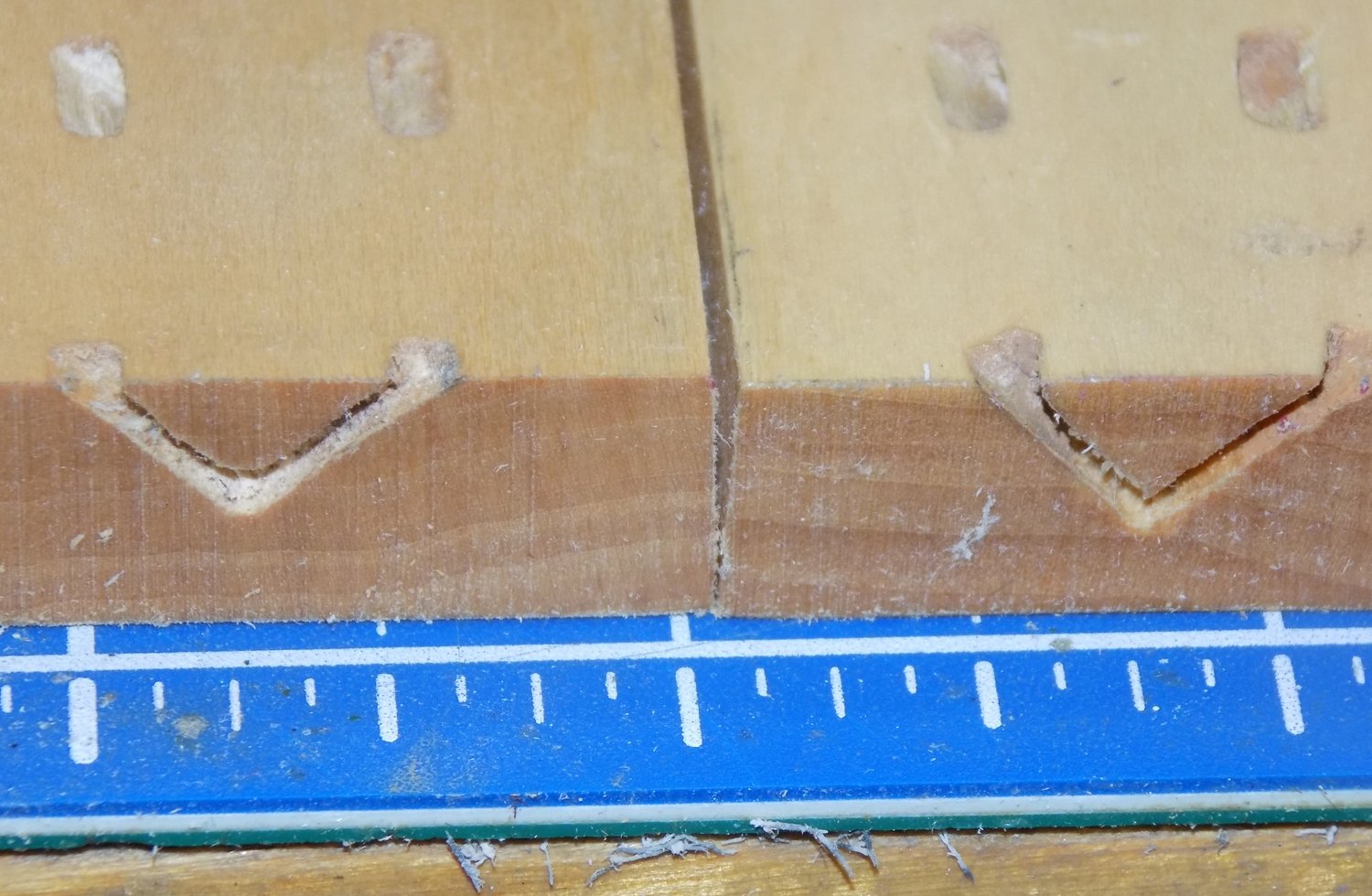
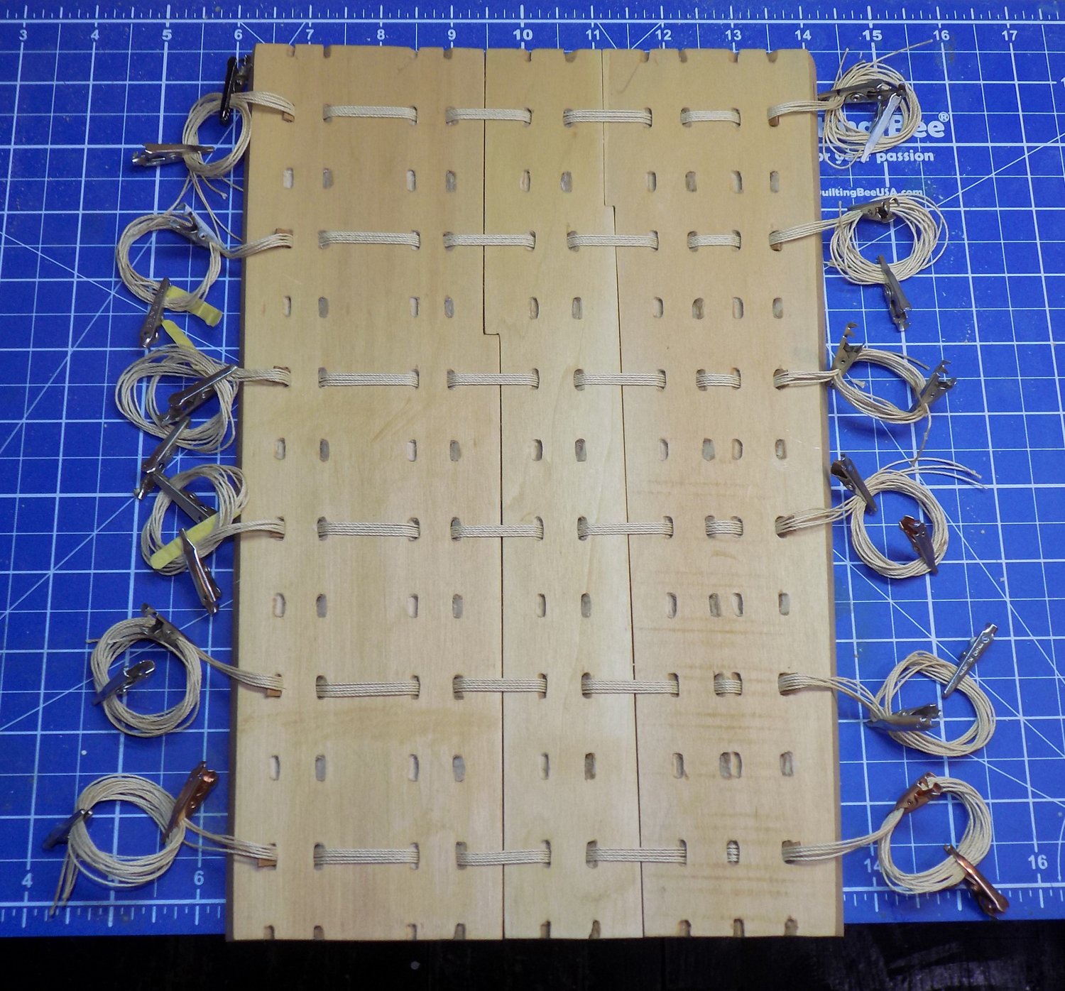
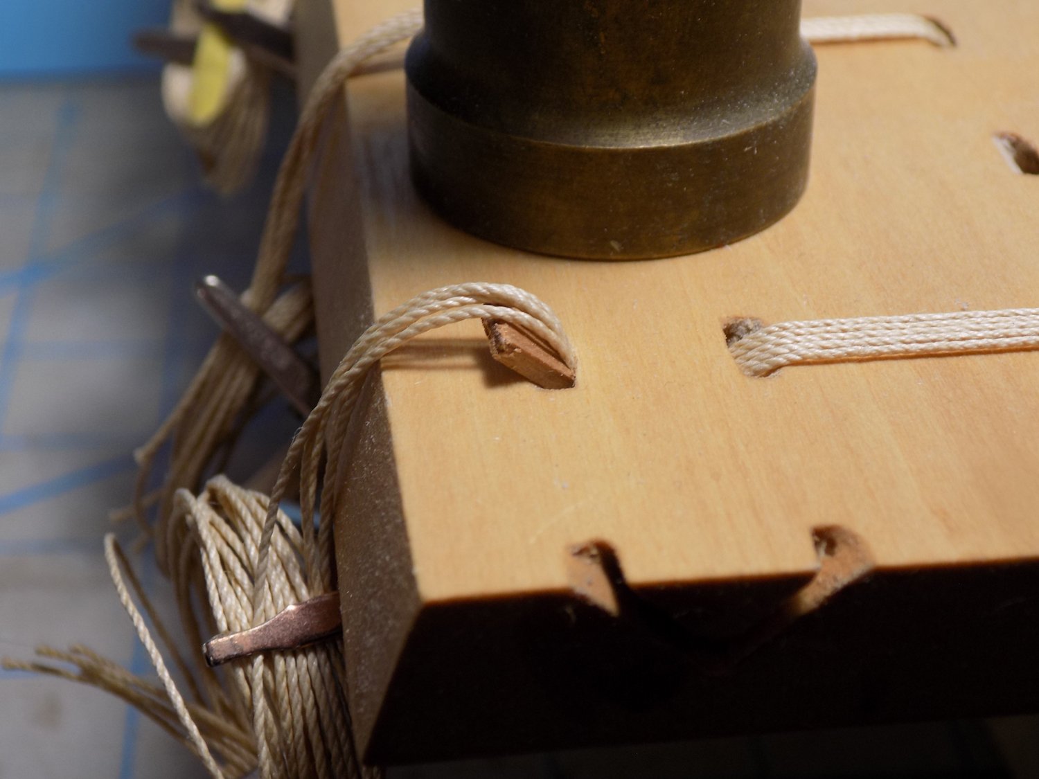
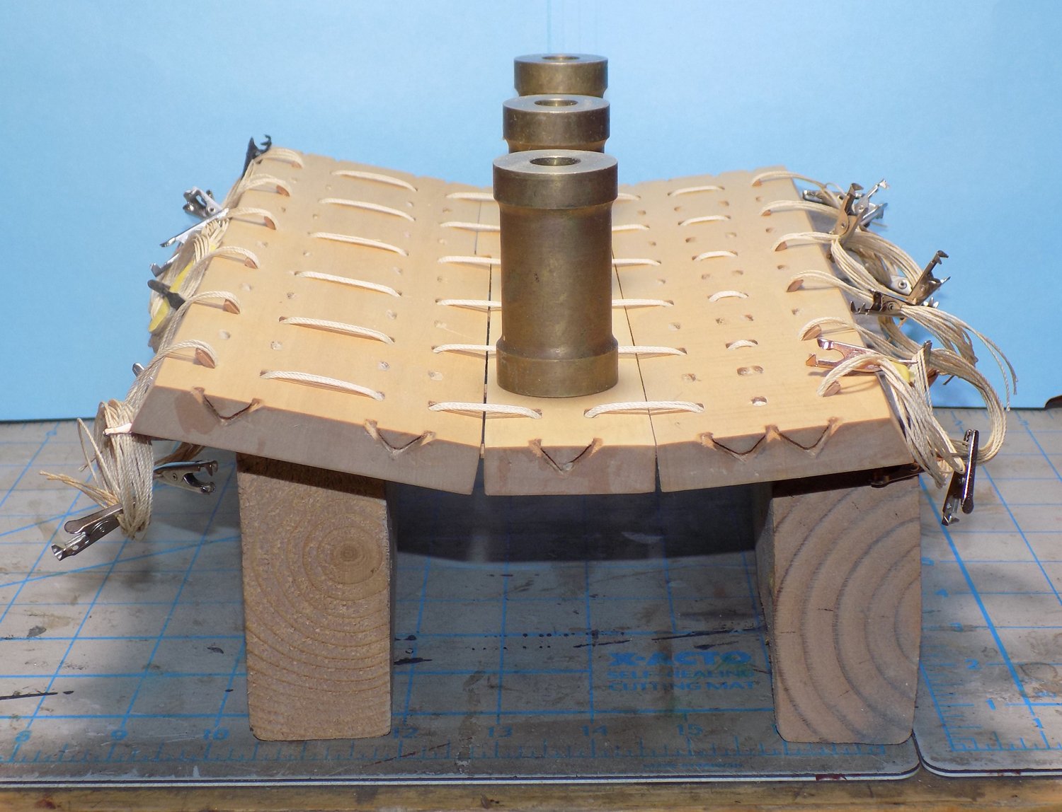
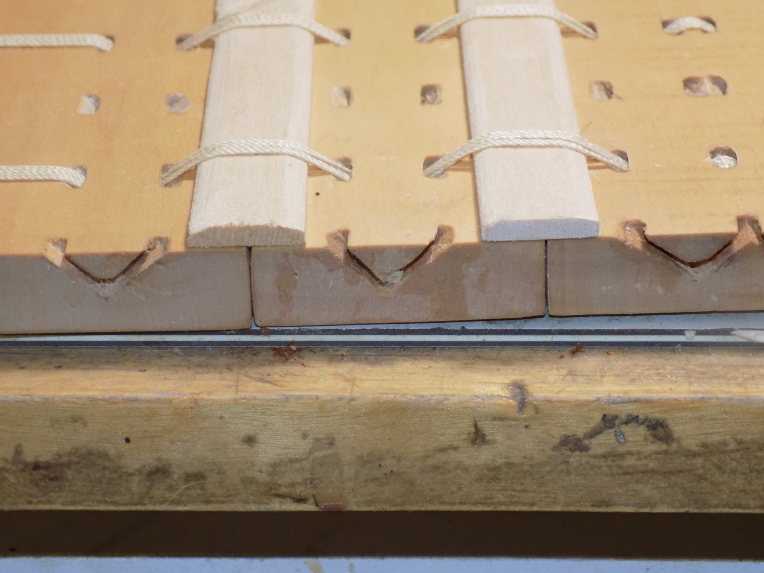
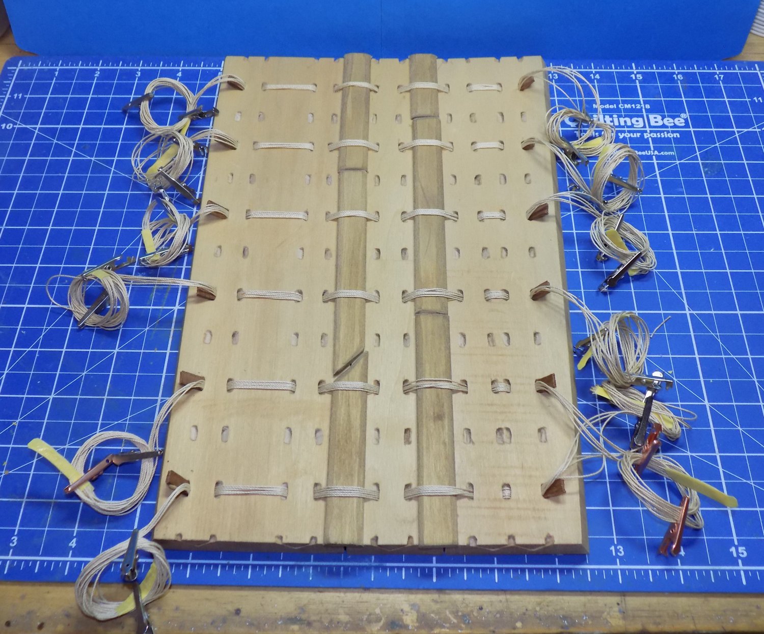
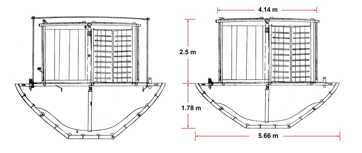
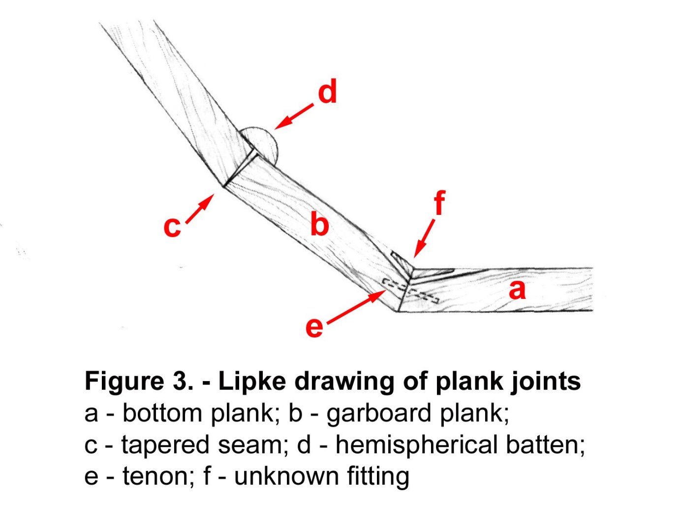
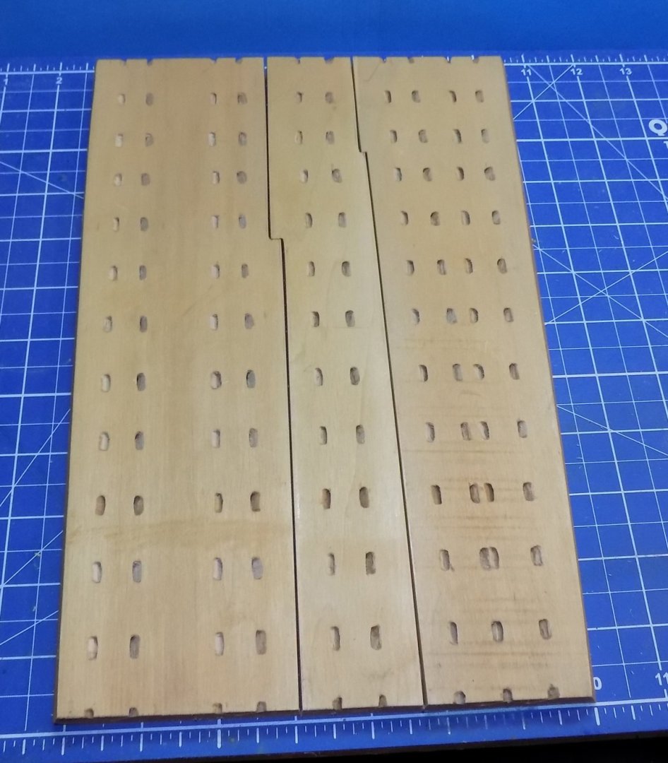
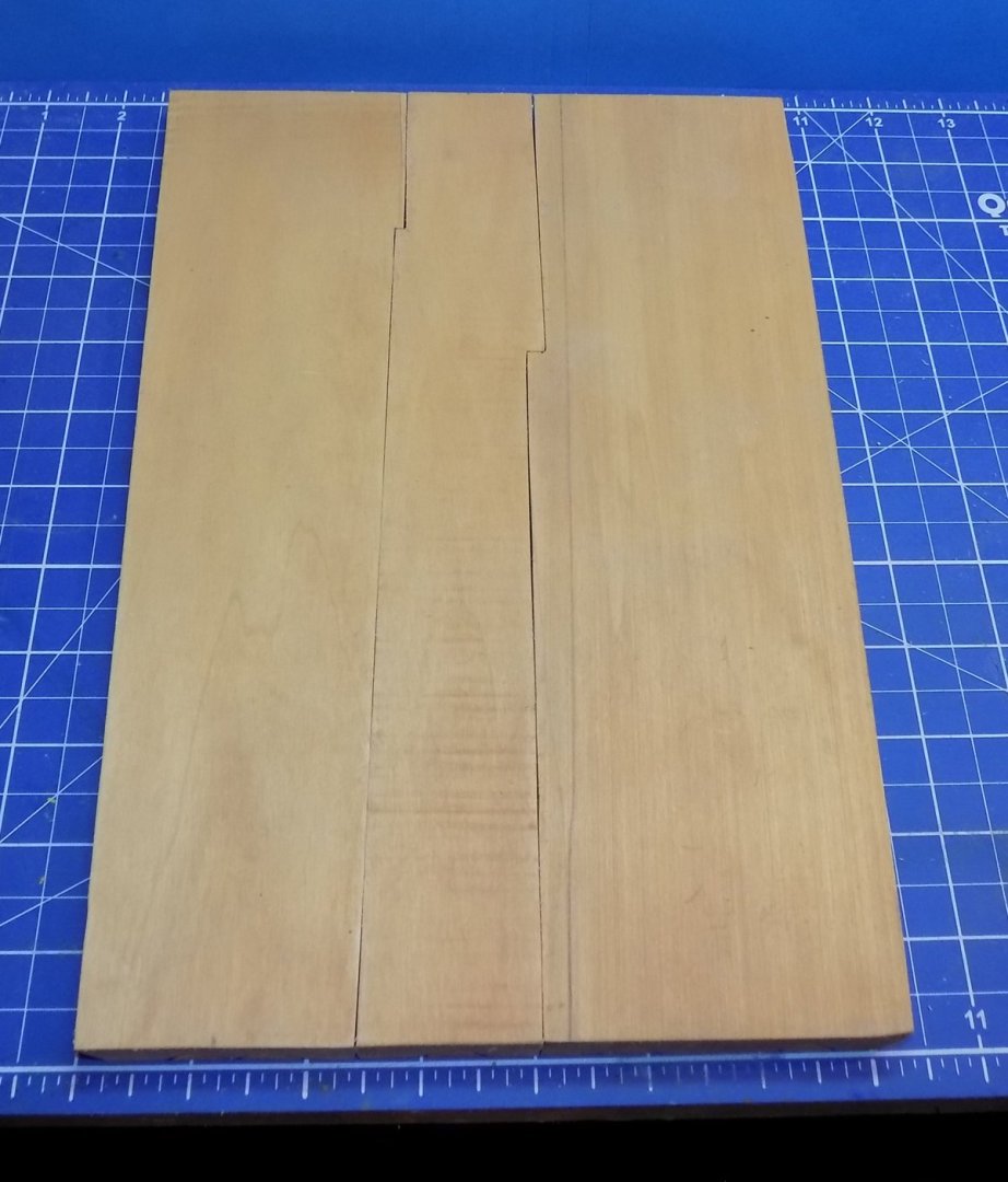
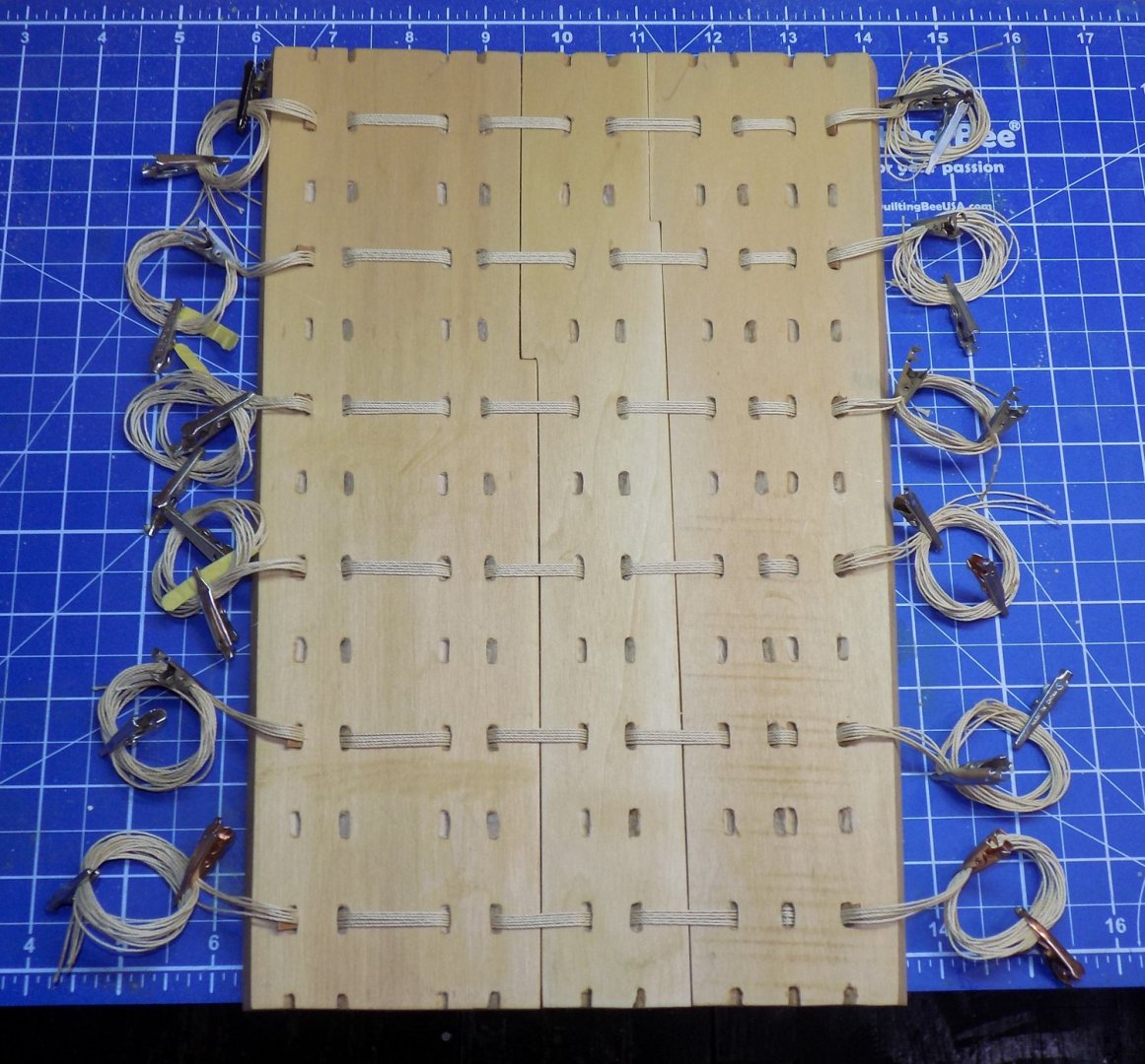
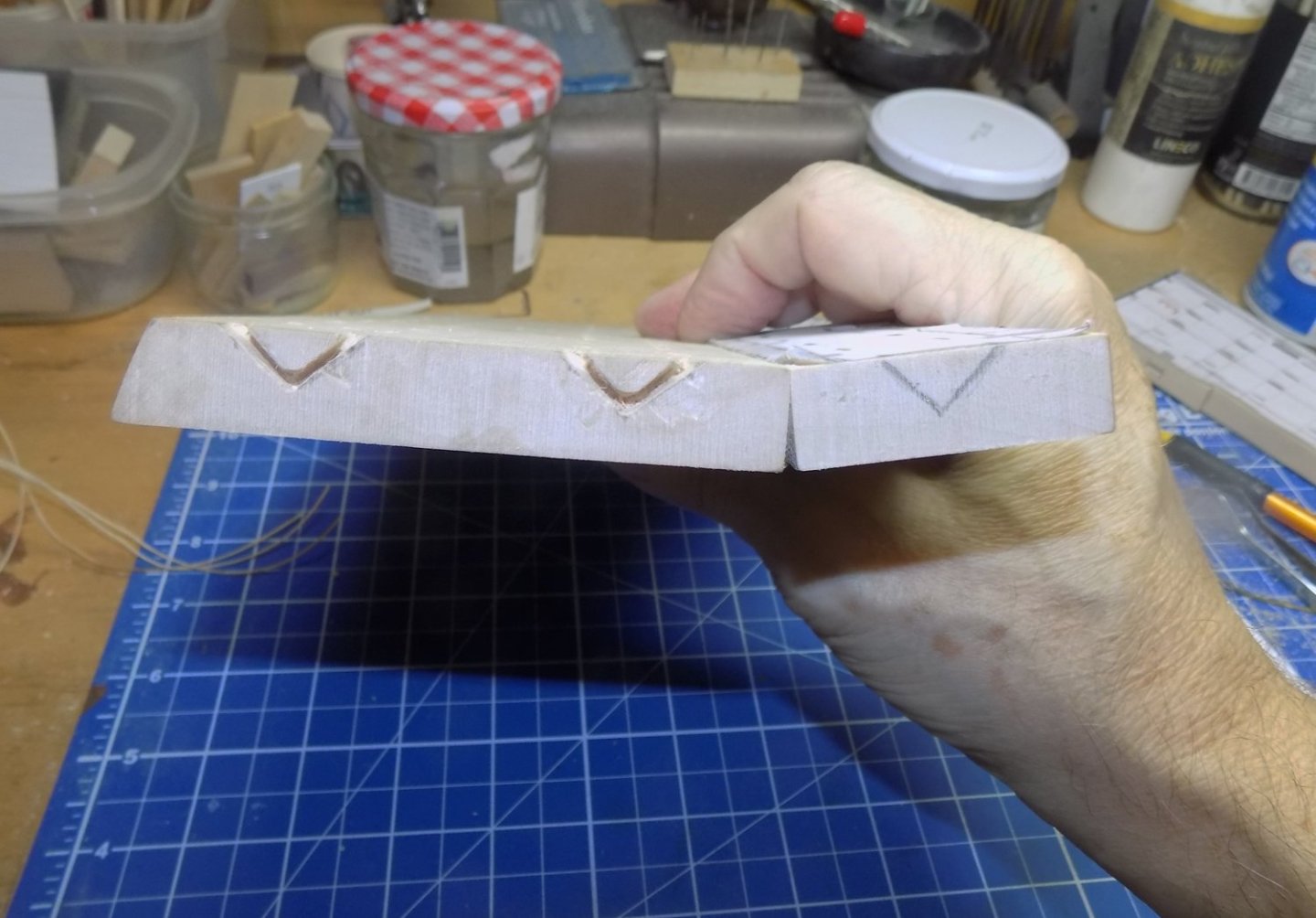
Hello again to all in this strange new year. Fortunately the Wayback Machine in my shop is set for 2500BC along the banks of the Nile, and I use it to escape the madding crowd. In the boatyard we left off with the center bottom planks of the Khufu boat cross section being shaped and laced. But before finalizing them I did some more forward planning for the model. To get to the final measured shape I went back to Paul Lipke’s excellent drawings of the vessel as printed in his monograph. Figure 52 has both a longitudinal cross section as well as a horizontal cross section drawn at the midships point looking aft towards the deckhouse. (Figure 1) I separated out the horizontal cross section drawing and compared its dimensions against those recorded by Dr. Mustafa (Lipke pp. 97, 103). When the beam at the sheer line was set to the recorded dimension I found that the draft was too deep and the deckhouse was drawn slightly too small. I’m sure that this was caused, in large part, from Lipke not having the actual boat to measure, rather than just Mustafa’s 1:20 scale model. Whatever the cause, in PhotoShop I adjusted the drawing to the dimensions and ended up with a plan that seems to match the shape of the hull and deckhouse as seen in the photographs. The flattening of the hull curve will be especially significant for the model’s final look. I’m sure that there will be a few additional tweaks, but this is my starting point. (Figure 2). In discussing the reconstruction of the boat Mr. Lipke provides further detailed information on the plank shapes. He notes that the joints between the planks are slightly open to the inside of the hull, but fit tightly at the hull’s outer surface. He speculates that this was so that “as the rail lashings shrank and the wood swelled (when wet) the hull would be drawn in on itself. With the inboard part of the seams cut away, the outer edges would be free to be crushed together all the more tightly.” (Lipke, p.105). These seams are all covered on the inside by over 300 battens which Lipke describes as “hemispherical.” It is unknown if the seams were filled with any type of caulking or packing material held in place by the battens, though that is certainly a reasonable possibility. For the model the edges of the planks were beveled at approximately 2 degrees, making an open top of about 1mm while the outer seams of the planks are as tight as I could make them. With the planks shaped and all the lacing tunnels cut, I turned to the lacing itself. Dr. Mustafa tried several types of rope and ultimately settled on linen line as being the most resistant to stretching. Fortunately, I have a large supply of laid up linen line with a diameter of .75mm (0.03”). This scales out to just over ¼ inch (for us American types) which may be a little skinny, but certainly in the right range. I laced every other set of tunnels across all three planks, doing six for the model. Each consists of five 36” lengths of line with the ends held together by layers of tape. Excess line was coiled to each side until additional planks are fitted. The lacing lines are held tightly in place with wedges in each outer tunnel mouth. Although they are not mentioned in any of my sources, such a simple solution is, I believe, very likely to have been used in this manner. Looking ahead I think that securing the lacing like this will allow me to ‘hang’ subsequent planks without having to rely on an internal framework or external shoring. But that is an experiment for another time. Now I could do some testing with this planking and lacing setup. The planks are joined with only the four small tenons sitting in vertically snug mortices along each of the two plank seams. Without any lacing the planks can flex up or down quite a bit before the planks start to separate. This would not be a good thing for a boat on the water to do. With the lacing in place the downward flex is substantially reduced. Here the center plank is supported on a 2”x4” while the outer planks carry two pounds of brass weights each. To increase the flex the lacings would either have to stretch, which the linen line resists, or slide through the tunnels, which the wedges prevent. However, the lacing does not interfere with an upward flex. Here the outer planks are supported while the center plank carries 3 pounds of brass. The lacings have simply loosened as the planks flex upward. Dr. Mustafa ran into the same problem. According to Lipke, even using linen line he could not get the planking to set up as firmly as seemed necessary. Ultimately he fashioned a few battens from scrap wood and worked them under the lashings over the plank seams. Lipke recorded Mustafa as saying: “Immediately that section of planking was much stronger and more stable. And then I laughed. I realized that I’d come up with precisely the ancient Egyptians’ technique in an independent way. . . Even skipping every other set of lashing holes, with these battens we got the hull much more rigid than before.” (Lipke p. 79) But these are not the narrow hemispherical battens shown in earlier drawings and models. As seen in the Primary Photograph they are considerably wider than would be needed to secure packing in the seam or otherwise reduce leakage. As measured in that photo they are approximately 16cm (6 inches) wide and appear to be no more than 3 or 4cm thick. Similarly, in this color photo of Dr. Mustafa in the fully reconstructed and laced hull, the battens appear to have about those same dimensions, or perhaps in places are even wider. So how do these battens stiffen the seams? To test this on the model I made up some wood pieces 16mm wide and 3mm thick. The lacings over the plank seams were loosened and the battens slid under them. The lacings were hauled tight again and secured with the wedges. Now, when the planks try to flex upwards the increased angle between them presses up on the edges of the batten and tries to lift it off the top of the planks. But this is prevented or reduced by the tight lacing. So here, with the same setup and weight as in the earlier photo, the amount of upward flex has been substantially reduced by the battens. Yes, this is a simple experiment done under not-so-controlled conditions. Nonetheless, the various pieces are all to scale and the principles, I believe, are sound. The conclusion that I draw here is that wide battens are important to the structural integrity of the hull and that this is their primary purpose rather than the prevention of leakage. Having investigated how the parts of the structure work together, I removed the test battens and replaced them with final stained ones that match the shape and sizes of those seen in the Primary Photograph. Next time I move on to the two garboards that will sit to the sides of the center bottom planks. Since the drawings of these planks are somewhat questionable they will take a good deal of photographic analysis to get them right. Till then, be well.


- 22 replies
-
- 18
-
-

-
Hi Johann - First, I love your work. I learn something new with every one of your posts, especially with the rigging. For these bowlines, could they simply lead through smooth holes, much like the holes in the mast caps in French practice where the yard halyards run over the rounded cap and then down to the deck? I also remember a multiple cleat block shown by Budriot on deck where the lines run through horizontal holes under the block before belaying on the cleats on top. Just another thought. Dan