shipmodel
-
Posts
941 -
Joined
-
Last visited
Content Type
Profiles
Forums
Gallery
Events
Everything posted by shipmodel
-
 Gary - If I am reading the photos correctly, some of the blowers seem to be set up to move the air into the ship, rather than being an exhaust. Would they have been done that way? It matters to the way I build the ductwork. Thanks Dan
- 238 replies
-
- 3
-

-
- leviathan
- troop ship
- (and 2 more)
-
Well, shut my mouth. . . I should have known that a builder as skilled as you was way ahead of me. Dan
-
Hi Michael - Sweet work, and done with a hand saw. Impressive. It's probably an artifact of the photo, but my eye says that the space between your 5th and 6th bulkheads may be too large to support the arc that the planks will need to take. As usual, I could be dead wrong.😉 Dan
-
Hi Gary - Thanks for the quite relevant information. I was hoping someone would know the actual name of those things. Now that I know how they work it will improve my construction of the rest a bit. Dan
- 238 replies
-
- 5
-
-
- leviathan
- troop ship
- (and 2 more)
-
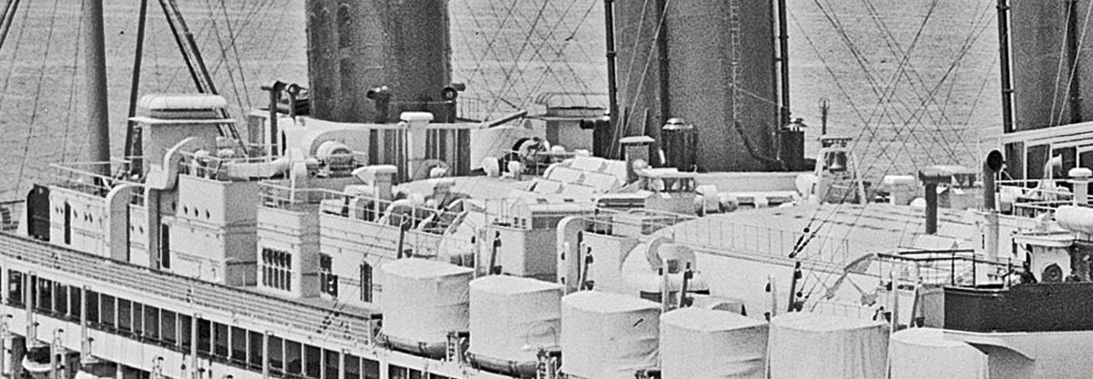
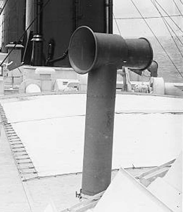
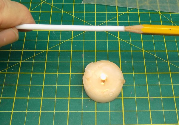
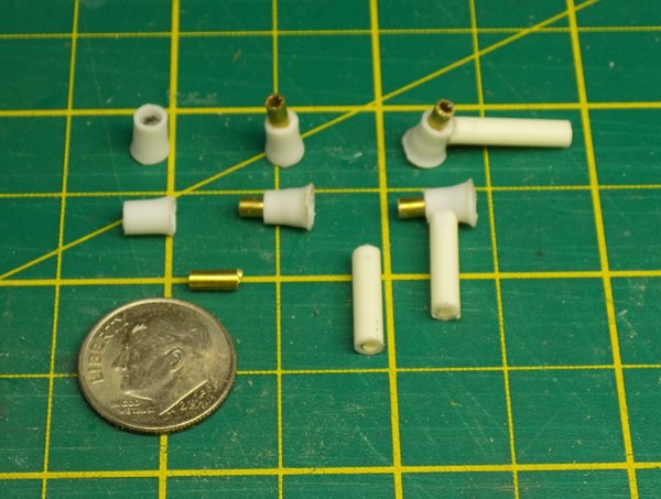
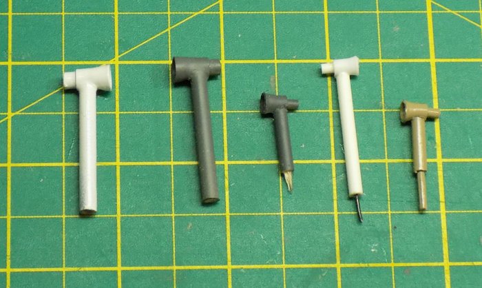
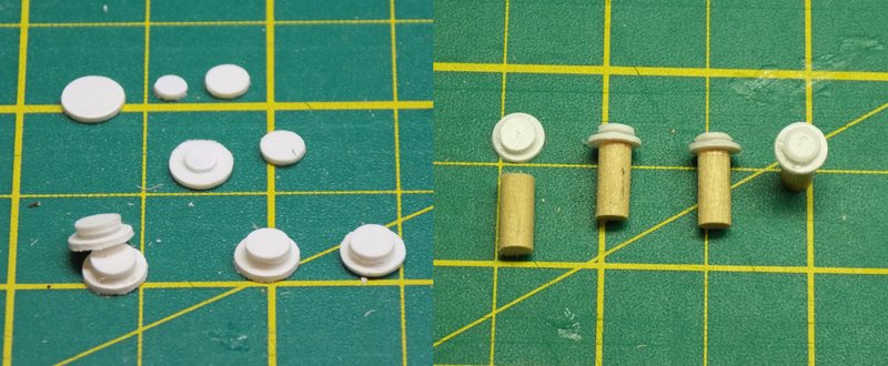
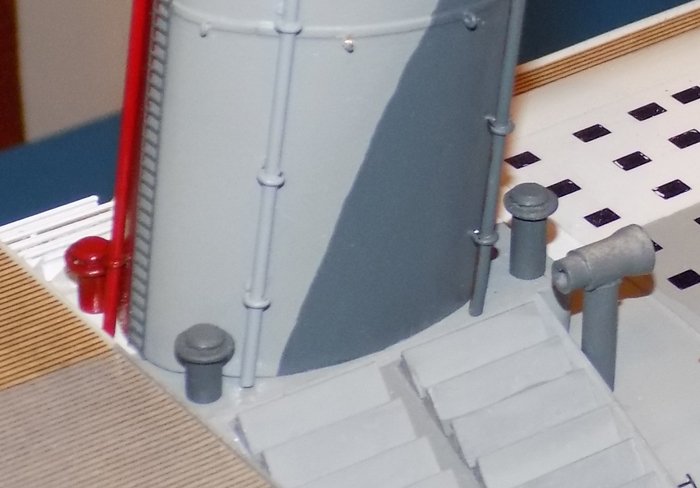
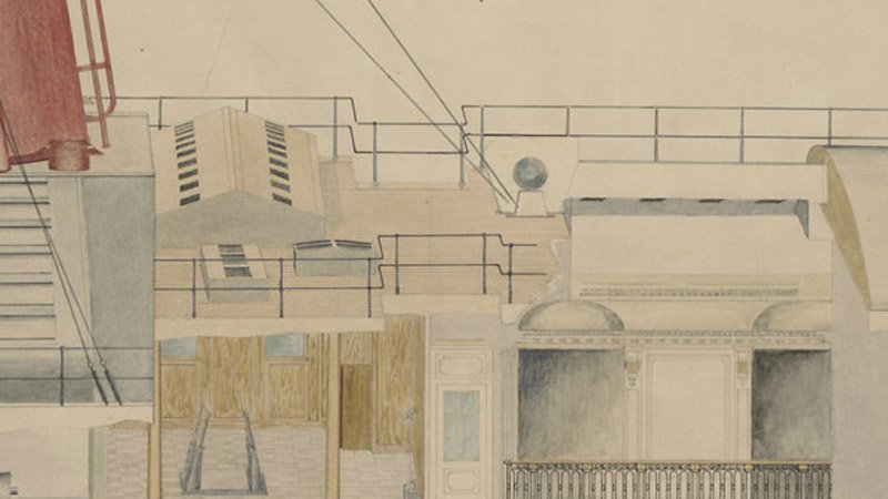
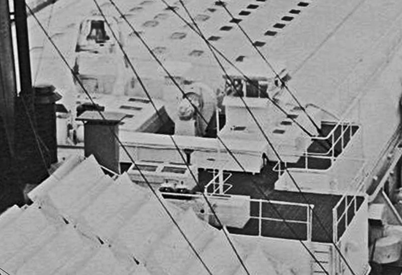
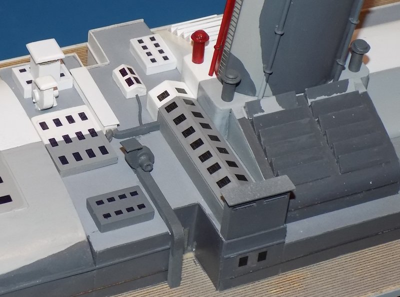
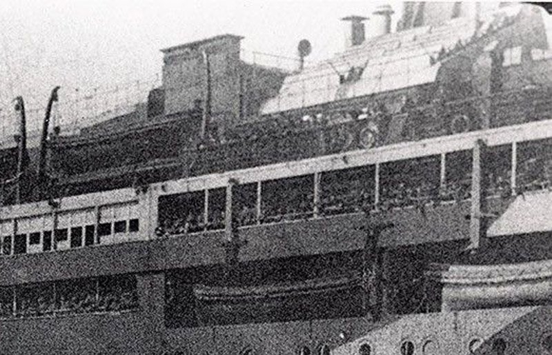
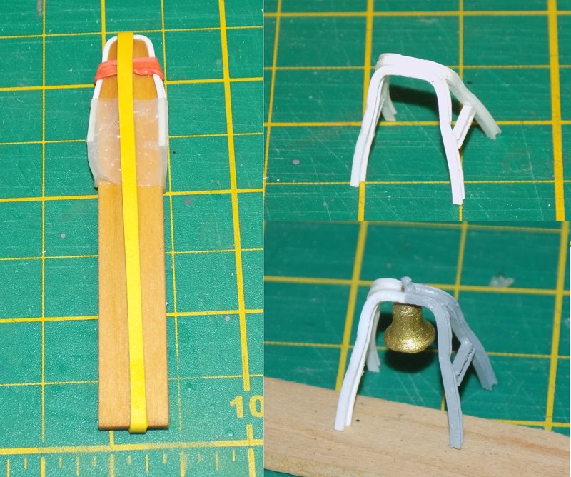
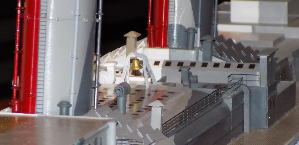
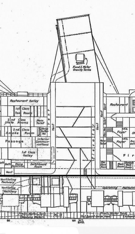
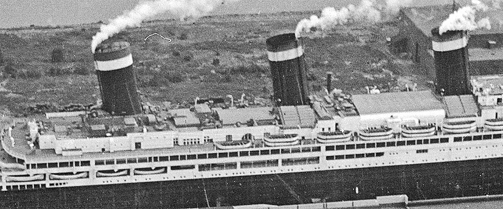
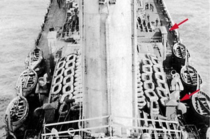
Hi all - Another Sunday – well, Monday – another building installment, after a nice diversion into engineering. Working now from the middle funnel down, I began with area between the middle and forward funnels. Here is the relevant section of the plans. Photo analysis provided the rest of the information needed. I started with the bases of the funnels themselves. Here are shots of the middle funnel and the forward one. The colors changed from the troop ship to the liner, but the fittings were the same. There are two types of small vents that had to be made, one with two tapering round plates, the other with a flared cross-head. Of the two, the flared head of the second made it harder to make, so I started with it. After a bunch of failed experiments, I found that I could make a flare in a tube with a pencil. A tea light gave me enough heat to soften, but not melt, the plastic. I held the pencil steady about two inches above the flame and rotated the plastic for even heating. The picture is a bit off, since I found that heating more of the pencil gave me a flare just on the very end of the tube. The flare was cleaned up a bit with sandpaper, then cut to the desired length on the Preac. A short length of brass tube was cut and glued into the flared tube, then a shaft was dished at the top and attached. There are two sizes for these vents and lots of different heights. After measuring and cutting the shafts to length the open ends were filled with toothpicks which also acted as handles for painting. Then the wood was cut off flush and drilled for a soft iron wire that will secure it to the model along with white glue. The round top plates of the other vent were made by punching out three sizes of plastic disc and stacking them so it looks like there is a gap between the top and bottom plates. This was attached to a length of dowel, which was used as a handle to sand down the top plates to a flat angle. Here are those fittings at the base of the forward funnel. I am a bit unhappy with the slightly crude look of the round vents. I could not get that edge as sharp as I wanted, since thin plastic will not take the same detail as metal. But to worry about that level of detail I would have to have 9 years to finish the model, not 9 months. All of life and art is a series of tradeoffs. Next was the area of deck just forward of the middle funnel. Here is the plan. There are a number of structures, but they are all too short to show up on any profile plan that I have, although an artist’s rendering of the cross-section of the ship gives some idea of their shapes. Photos of the area were studied closely to make out the shapes that fit the plans. But most of them are from the liner period, and some seriously creative interpretation had to be done to fit what was seen in the few troop ship photos showing this area. For the most part, the structures here are rectangular, though of different heights and a few with sloped roofs. Most have rectangular or square skylights which will be represented with dark decals. However, in the center of this photo there is a ducted fan that I call, for obvious reasons, a snail. This and other photos show this type of machinery in lots of other locations around the upper deck. They come in several sizes, with varying details, but they all follow a similar pattern. There is a round flat body with a motor on one side sitting on a motor mount. There are intake and exhaust ducts coming off at various angles, with various end caps or fittings. I experimented with styrene and resin, but I am basically a woodworker. Each body was sliced from a hardwood dowel, as was the motor. I did not try to do any detailing of the motor except in the largest sizes. When lying down the disc has its grain running vertically, so it is easy to line up a knife blade and press down vertically. The wood splits cleanly away. Ductwork the width of the body is glued to the cut face and rounded to curve into the disc. It is topped, in this case, by a rounded square cap. After priming, sanding and painting these snails were located, secured and attached to the ductwork shown on the plans or photos. There are two here, along with my best interpretations of the houses, skylights and vents. More than most other areas of the ship, this one shows the changes from the troop ship to the liner. I try to check my progress regularly against photos to be sure that I am not getting too far away from reality. Here is the developing troop ship from a low angle. I think I am on the right track. Just forward of this area there is a large belfry. This houses the largest of five bells on the ship, and the one left over from the SS Vaterland. It was built up from 1/16” scale I-beams. The pieces were gently bent around a form and rubber banded there. A dip in simmering water and a dunk in cold set the U-shapes which were joined at the top at an angle. Cross supports were added and welded in place with liquid plastic cement. After painting the bronze cast bell was mounted. Forward of the belfry is the curved roof skylight over the Social Hall with the individual lights represented by a custom decal. The camouflage scheme was carried up and over since it could be seen from the side. Photoetched railings and ladders were fitted in place as seen in the photos. From the angle of the port bridge wing the model closely resembles the ship and is starting to get the busy look that she had. Nothing draws my eye as being off and, as they say, “If it looks right, it must be right. . . “ Another segment next Sunday, god willing and the creek don't rise. Till then, be well. Dan


- 238 replies
-
- 23
-
-
- leviathan
- troop ship
- (and 2 more)
-
Hi JD - The rigging is coming along beautifully. The baggywrinkle is delightful. Dan
-
Hi Roger, Lou - If you send me your email addresses I can send the file with the entire cross section plans. Reproducing it here will not have the kind of resolution that you want. Dan
- 238 replies
-
- 2
-
-
- leviathan
- troop ship
- (and 2 more)
-
Hi Roger - Thanks for the info. I may never use it, but it is interesting nevertheless. Lou - Don't worry about hijacking my build log. I find these little diversions, whether in my log or another's, to be one of the better features of this site. Nils - Thanks so much. I only wish that I was on the final lap. There is a huge amount of detailing to be done, even before I get to the 70 boats with their davits and pulleys, plus over 100 life rafts on the troop ship side. Then there are the masts, and the cargo cranes, and and and . . . Dan
- 238 replies
-
- 6
-
-
- leviathan
- troop ship
- (and 2 more)
-
Hi Michael - Thanks for the warning. I haven't had that problem yet, and maybe the boiling and cooling will limit it. I will think twice before using the technique again. Dan
- 238 replies
-
- 2
-
-
- leviathan
- troop ship
- (and 2 more)
-
Hi Lou - I looked at the plans again and found two large drinking water tanks all the way aft and down near the propeller shafts. Near them are several washing water tanks, while the bilges aft of midships are all labeled as tanks for either washing or boiler feed water. These would have to be pumped up for use, so the small tanks in the funnel would probably only be called on when the power went down. If they used salt water for anything, it might have been pumped in directly from the sea, but salt deposition would be a major problem in pipes, I would think, so I am not sure that it was used. I am anything but an expert on ship design or maintenance. I mostly concern myself with outward appearance only, so I could be completely wrong here. Dan
- 238 replies
-
- 2
-
-
- leviathan
- troop ship
- (and 2 more)
-
Lou - Your question got me wondering just what was inside. According to the refit plans there is a large vent pipe that runs up along the aft side and reaches all the way to the engineering decks near the bilges. It services the restaurant galley, among other spaces. Other vents at the forward end do not have a separate pipe, they just open into the funnel at its base. That's why the Vaterland had the openings, I believe, During the war there must have been other arrangements made, but the plans don't show them.
- 238 replies
-
- 5
-
-
- leviathan
- troop ship
- (and 2 more)
-
Hi Lou - I probably agree with you, because I know that the last funnel on the Titanic was a dummy, as you say. However, although the plans indicate that there were water tanks inside the third funnel, they also indicate a smoke or steam pipe in it. In the absence of anything definitive I opted to make the top of the funnel pretty much match the other two. Dan
- 238 replies
-
- 3
-
-
- leviathan
- troop ship
- (and 2 more)
-
Keith, Druxey - thanks for the compliments. Carl - it turned out to be less difficult than I expected. The funnels were pretty smooth at that point and the Frog tape that I used is very good at masking a straight edge. I also aimed the paint spray from the masked areas over the edge of the tape, and not against it. There were only a few spots that had to be touched up. Any curved edges, and all of the pipes and details, were painted freehand without masking. Thanks for asking. Dan
- 238 replies
-
- 6
-
-
- leviathan
- troop ship
- (and 2 more)
-
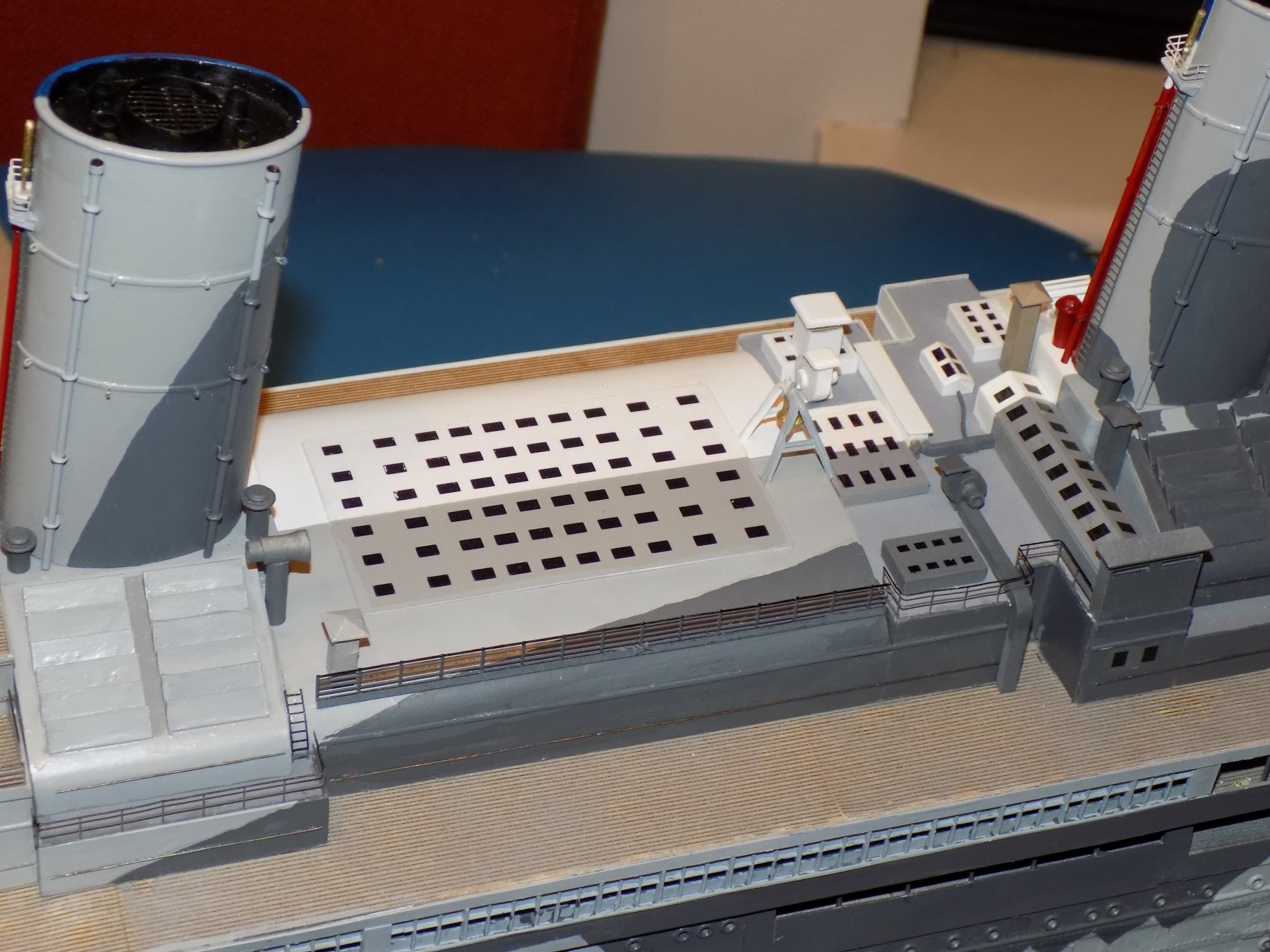
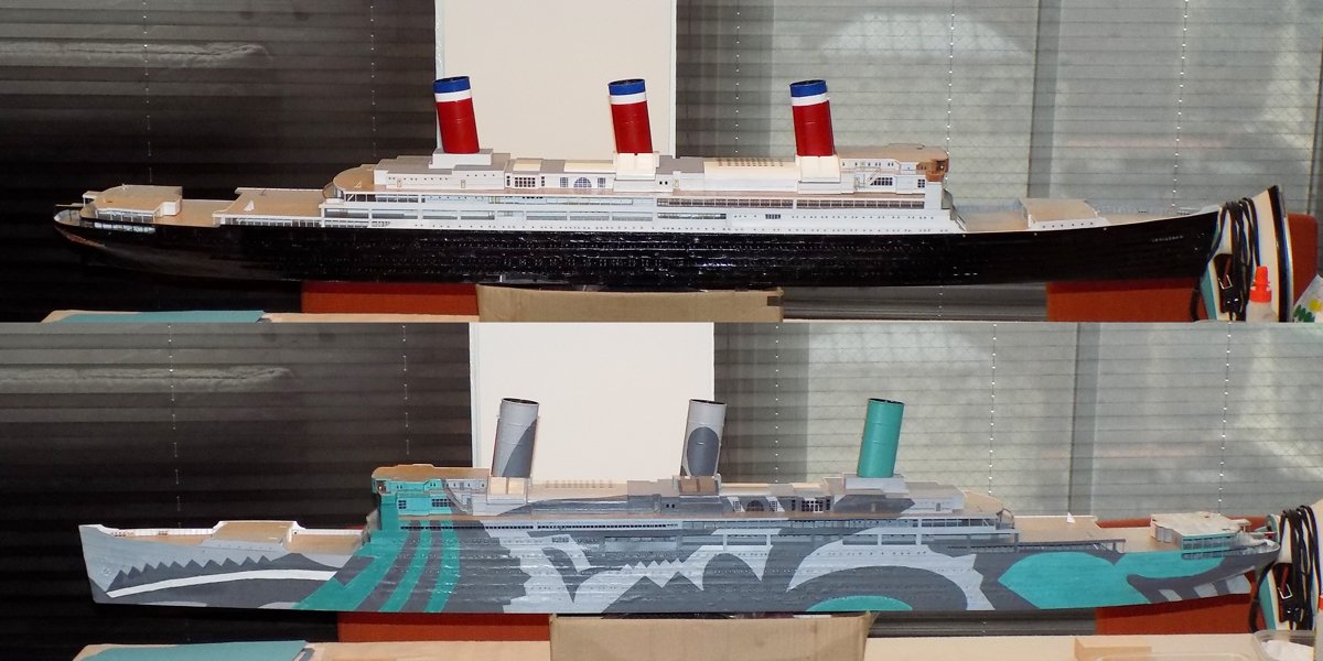
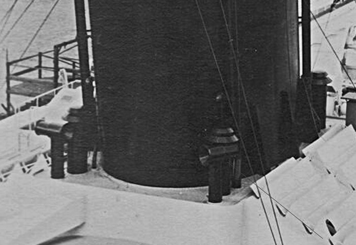
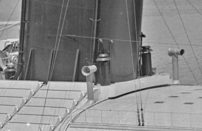
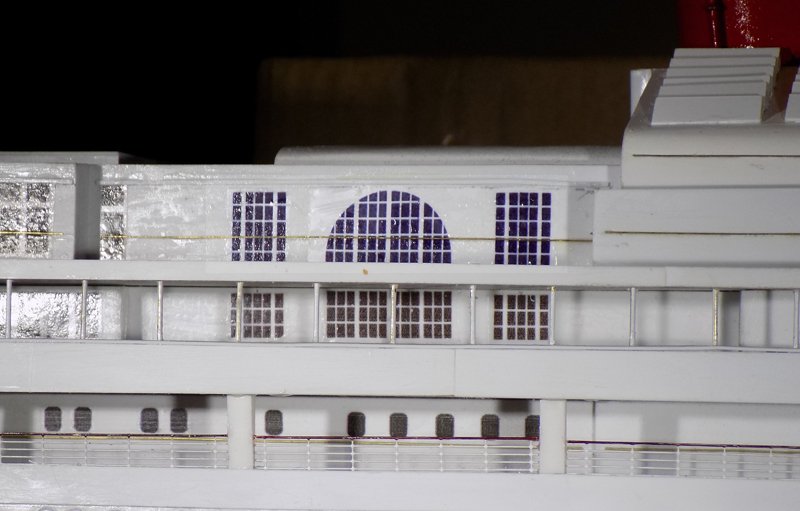
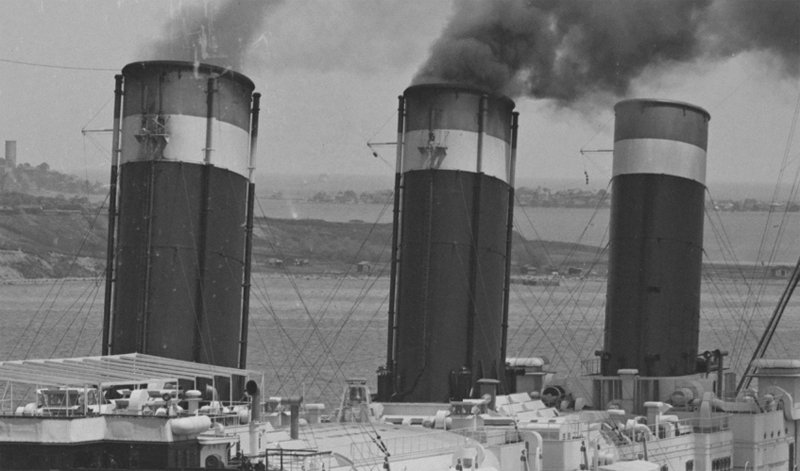
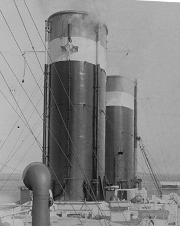
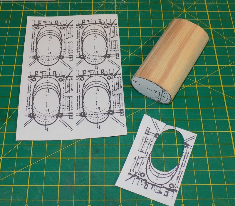
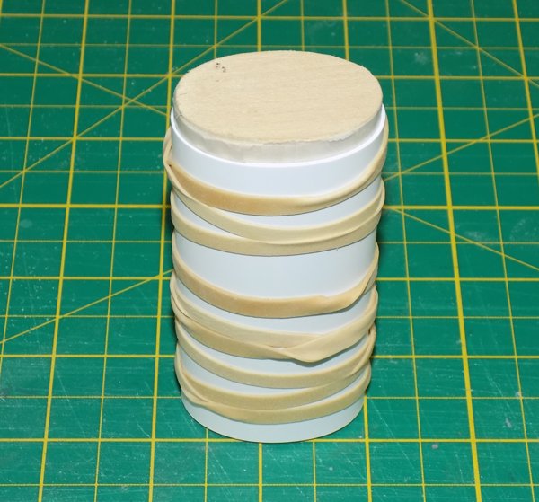
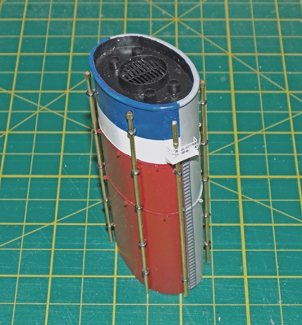
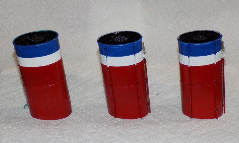
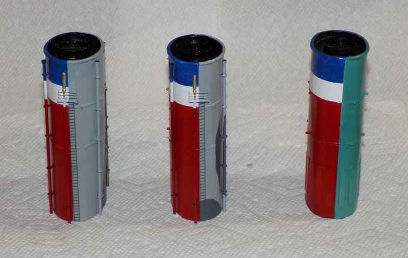
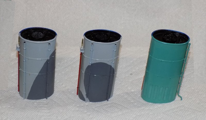
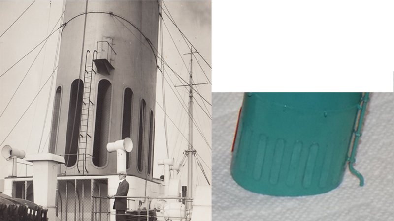
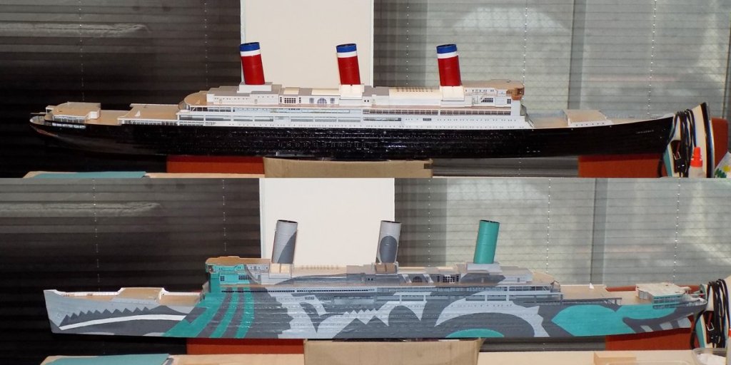
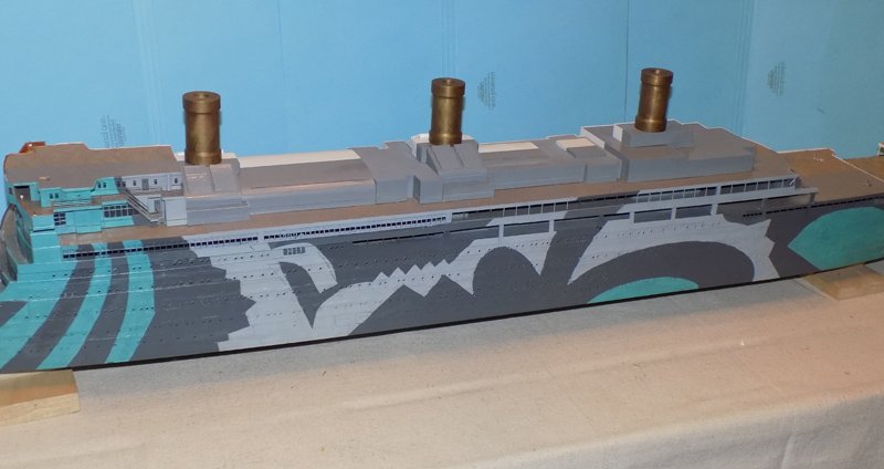
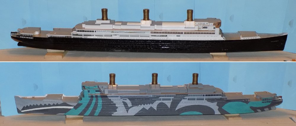
Hi again, and thanks as always for the likes and compliments. Druxey, those are stealth funnels. . . Continuing with the build, now that the uppermost deckhouses were framed out their sides were detailed. First the camouflage scheme on the troop ship was carried up and over the sides, even over the angled louvers and the rounded cover over the large salon. Doors, windows, portholes, moldings and handrails were added with their locations taken from the plans and photos. All of the large structures on the ocean liner side were left or painted white with brass handrails. The decals for the double-deck height windows of the Winter Garden were carefully lined up, even though it is difficult to see the lower windows unless the light is just right since they are deep under the overhanging deck. Railings were added to three of the open spaces that house boats on the troop ship. The next elements to tackle were the three funnels. Size and location were taken from the plans, but they are not very detailed, and what they show is confusing. I work better from photos so here they are. They are oval cylinders with no taper and rake back at 8 degrees. The liner funnels were painted red up three quarters of their height, with the top quarter divided equally between a lower white band and an upper blue one. The forward two have four ancillary pipes spaced equally around them, though the third funnel does not have them. Other photos show that the last funnel has one pipe that runs up the back just to port of the centerline. In this close-up you can see that there are two reinforcing bands for the attachment points of the guy wires. One is halfway up, the other just below the white band. There is a rounded lip at the top of each. A steam pipe runs up the front of the second funnel to a platform where a foghorn is mounted. This does not appear on the last funnel. Other photos are a bit unclear, but seem to show a double foghorn on the front of the first funnel and ladders leading up. Construction began by carving a mold out of pine. The best image of the plan view of a funnel was cut from the plans, then resized to be 1mm smaller than full size in both width and length. I copied it six times and printed them on one page. Two were cut out and glued to the top and bottom of a rectangular billet that was a bit taller than needed. Care was taken to be sure that they lined up with each other. The excess wood was removed with a coarse sanding drum in the Dremel, then a medium grit belt sander, and finished with a fine sanding block. The resulting cylinder was sealed with several coats of clear finish and sanded smooth. I wrapped it with waxed paper, then two layers of 0.010” sheet styrene. The four total thicknesses of the plastic add up to 0.040”, or 1mm, bringing the outer dimensions back to full size. To make the plastic to permanently take on the right shape I tried a technique I read in FineScale Modeler magazine. I wrapped it all around with several rubber bands, then dunked it in simmering water for 20 seconds, then cooled it in cold water. With the rubber bands removed I could open the outer layer slightly without taking it off the mold to feed in some thin Tamiya plastic cement, which had enough working time that I could close it back together and secure with rubber bands until the glue dried. The exposed edge was ground and sanded smooth and flush. After sliding the plastic off the waxed paper, and despite the boiling and cooling, the funnel returned to a much too tubular a shape. I was a bit disappointed but I always planned to use the mold to shape and stiffen the funnel. However, it had been quite a long process to shape the mold, and I would have to do two more. Then I had the idea to cut the mold into nine pieces. For each funnel I slid one piece into the middle of the tube and glued it there. Pieces were secured in the top and bottom, the top one set down a little. A half-round strip made up the lip at the top and narrow strips were added for the eyebolt reinforcements. The bottoms of the funnels were shaped to the 8 degree angle on a disc sander. All three were primed with dark grey before being tested in place for angle, lean, and symmetry. Once their overall shapes were acceptable a set of tiny eyebolts were twisted up and installed. There are eight evenly spaced along each of the reinforcing strips, a total of 48 on the three funnels. Then the troop ship sides of the first two funnels were sprayed light grey and the camouflage pattern hand painted according to the plans in dark grey. The third funnel was painted with the blue-green color. Then the centerlines were located and masked with the Frog tape. The top of the liner side was painted white, then masked so the lower area could be sprayed with a medium red and the top brush painted Navy blue. The outside pipes were made up from 1/16” brass rod with small sections of brass tube fitted to the top. They are secured to the funnel with five eyebolts. I found some commercially produced ones in my spares drawer that fit perfectly. To line them up I laid on a narrow strip of tape and drew a straight line on it. Eyebolt locations were marked and holes drilled. After removing the tape and gluing in the eyebolts the pipes slid in without a hitch where they were secured with dots of epoxy. On the front face of the first two funnels I added a dark painted PE ladder on the troop ship side and a thinner steam pipe on the liner side of center leading up to a small railed platform to service the foghorn. The top of the funnels does not appear clearly in any photo that I have, so I took some guidance from the interior structures seen in the cross-section plan and gave them a large central ring protected by a PE grating. On the forward two funnels there are also four smaller pipes epoxied to the wood plug, while the last funnel only has one. Then the tops were painted flat black. The external pipes were brush painted to match the background colors. Here are the liner sides. The forward faces. And the troop ship sides. There was one final detail. At the base of the third funnel the photos show a series of flat plates rounded top and bottom. I did not know what these were until I located a photo of the original funnel on the SS Vaterland. There they are open holes, probably for air circulation. They were closed off during the war and left that way later during the liner incarnation. I thought that they made a nice detail, so I made them up out of 0.005” strip. They were painted off the model before installation and the different tones make them stand out just enough to see if you look for them. So here is my usual final double photo. All of the structural elements have been built up from the waterline and in from the bow and stern, finishing with the center funnel. Now begins the fun work of detailing the ship from the top down and the center out. More soon. Be well Dan
- 238 replies
-
- 19
-
-
- leviathan
- troop ship
- (and 2 more)
-
Hi Gaetan - A tip of the hat to you and to Vossiewulf for clearing up my questions as to why some of the knives on "Forged in Fire" will not cut. Your dedication to sharpness reminded me of Terry Pratchett's character Death, who hones his scythe on leather, then wool, cotton, silk, and even the wind. He finally gets the edge that he wants with sunlight itself. If you are going to sever the soul from the body you should have the sharpest blade possible. I guess every job has its need for its own kind of edged tool. Dan
-
I'll be following along as well. I have used it sparingly, but I am more and more fascinated with the possibilities of this new technology. Dan
- 133 replies
-
- 4
-
-
- alert class
- tugboat
- (and 1 more)
-
Pulling up a chair myself. Dan
-
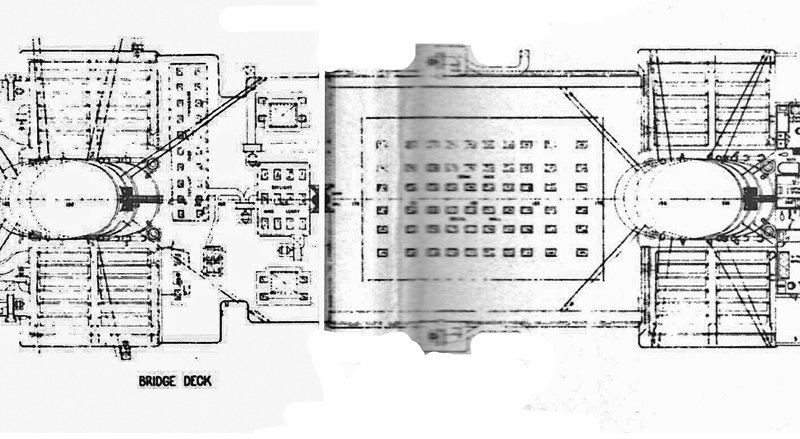
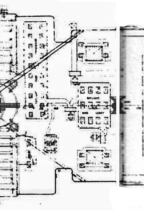
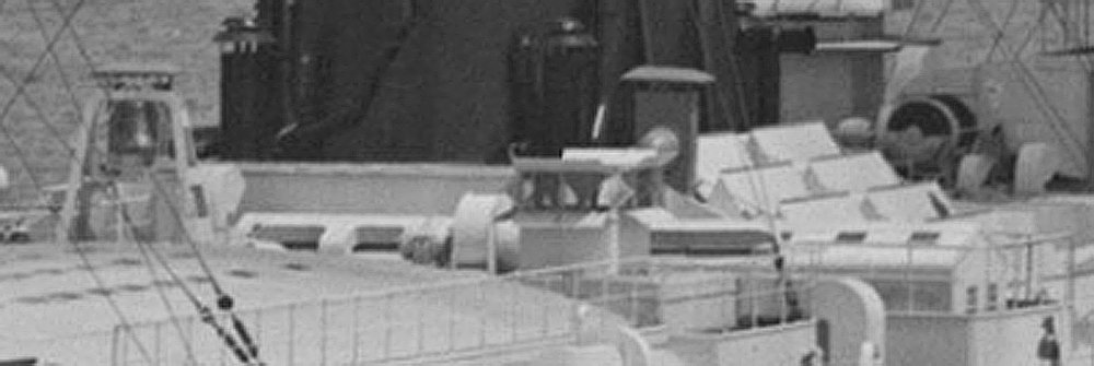
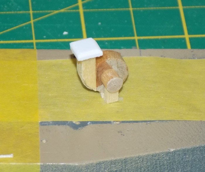
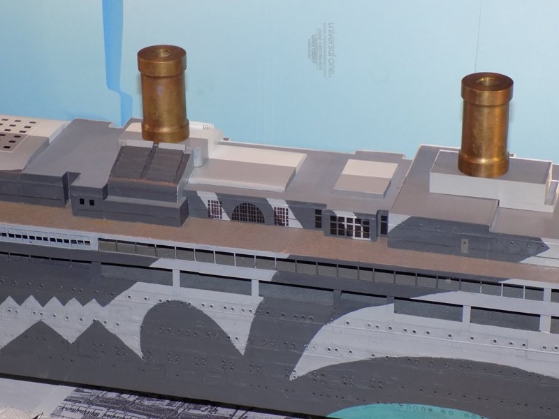
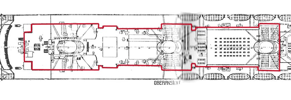
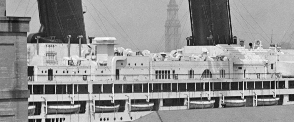
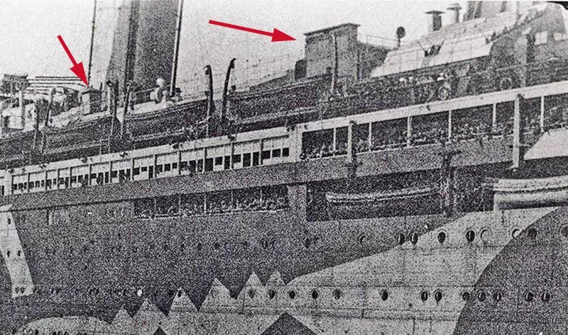
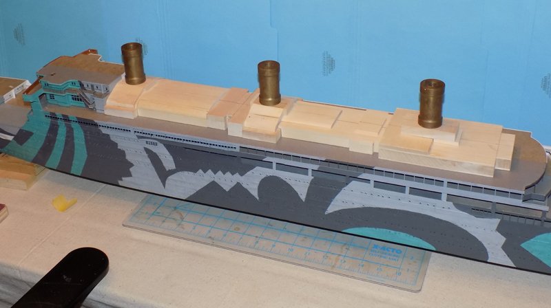
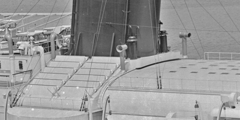
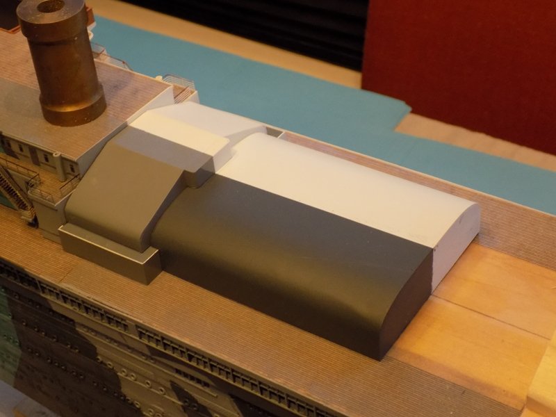
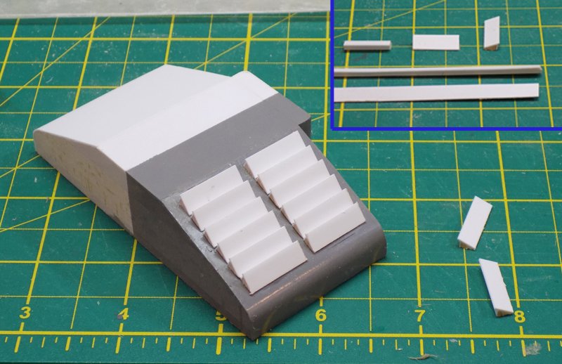
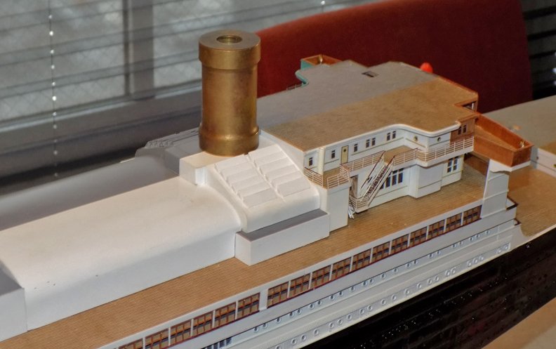
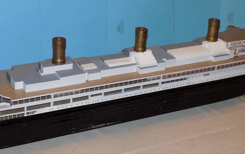
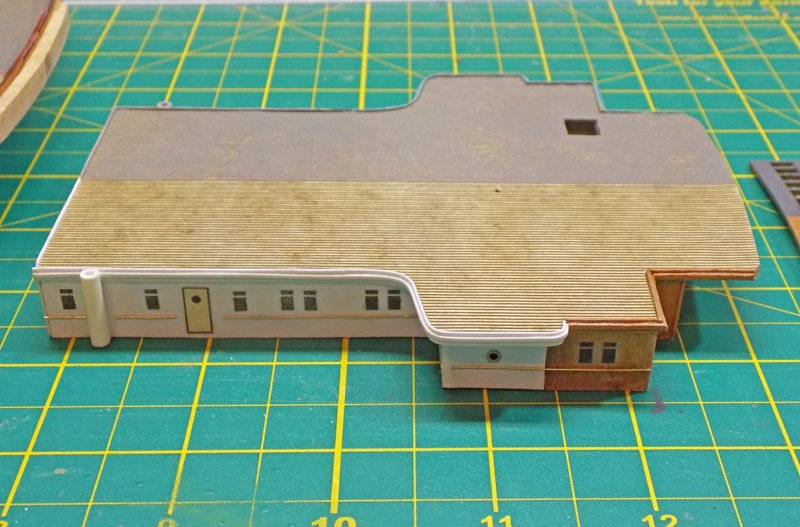
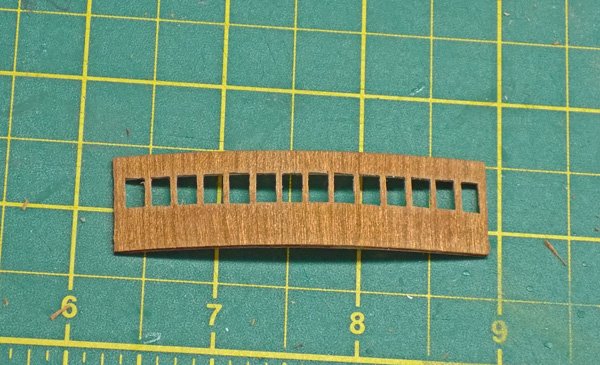
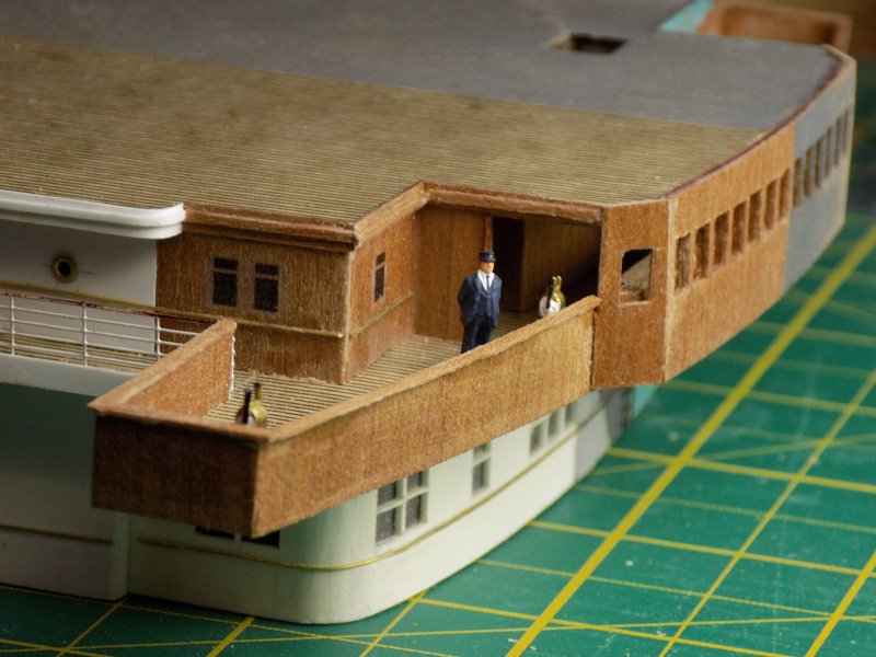
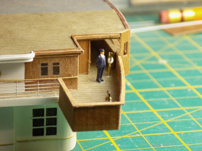
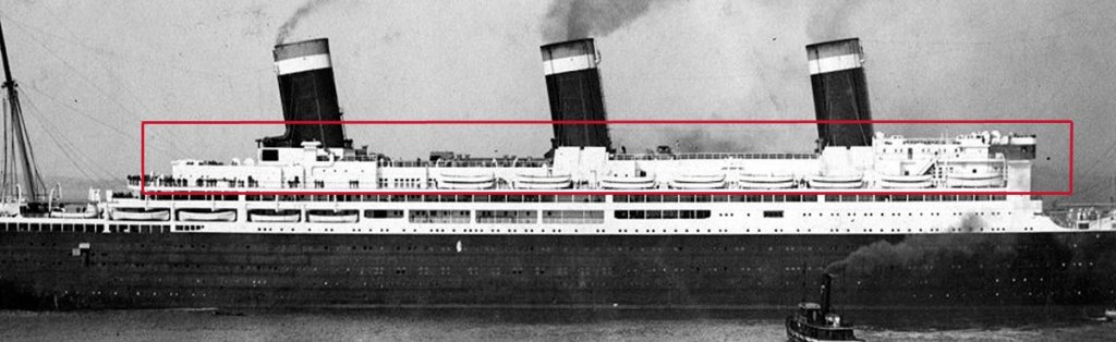
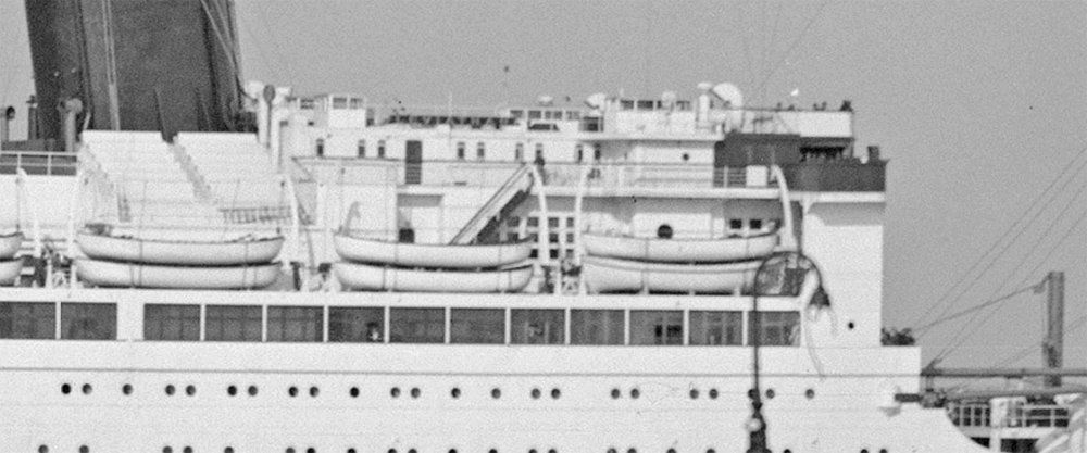
Hello again to everyone. I am trying to have the log catch up to the build, but I keep getting distracted by reading the excellent build logs from Michael, Rick, Gaetan, Keith, and all the others who are sharing their tribulations and triumphs. Thank you all. Meanwhile, in the Brooklyn dry dock the Leviathan is closing in on the last structural elements. The A Deck house aft of the forward superstructure will complete the major constructions. In the photo this area does not look that complex, but this is deceiving. The plan view shows how irregular the outline is, with more nooks and crannies than an English muffin. For some reason this deck plan is rarely reproduced. This is the best one that I could put together. It was taken from the end papers of Frank Braynard’s book and, from the label of “OBERANS. . . .” it is clearly the plans of the Vaterland and not the Leviathan. It also suffers from crossing the gutter between the pages of the book, and a section just ahead of the middle funnel is blurry. Photographs show that the area is even more complex than appears on the plans. Deck house heights go up and down and the roof is busy with all sorts of machinery and small structures. Higher resolution photos confirm this complexity, but since they are taken of the ocean liner, the overall white color scheme makes teasing out the details difficult. Ventilators, ductwork, machinery and even a belfry can be made out, but exact sizes, placements, and relationships between them are an ongoing challenge. Then there is the problem that the troop ship varies quite a bit from the ocean liner, and not just because of the camouflage. Here, for example, two large structures can be seen that do not appear on the liner. Ventilators? Lookout positions? Range finders? Their size and locations have to be accounted for even while the basic structures are built. Combining all of the available information, I came up with a series of shapes that were roughed out in basswood. The three brass weights stood in for the funnels so I could get an idea of relative heights and placements. Starting at the forward end I did some basic detailing of the support areas under the funnels. Both the forward and middle funnels stand on bases with angled sides and curved ends. 12 louvers sit on each side. Here is the forward one after sheathing and painting, with the next section aft, the rounded top of the main salon. The paint on the salon camouflage is just the primer, which is too dark and was corrected later. Neither piece is permanently attached at this point. Louver pieces were made of wood and styrene. They are flat triangles which were made up as a long strip, then parted off to the correct length (see insert). The 48 louver sections were made up and installed on the two bases. After final sheathing and painting of the forward base and the salon cover they were carefully positioned and secured. You can see how they interlock with some areas of the base overlapping the salon, while other areas of the salon overlap the funnel base. Fitting together this bit of jigsaw took some time and care. Continuing aft the rest of the interlocking sections of the deck house were fitted, sheathed and painted. Despite the care that I took there were still one or two small gaps that had to be filled with slivers of sheathing. All of the flat roofs were painted uniform grey on the theory that there would have been no reason in 1917 during WW I to camouflage areas that could only be seen from the air. The troop ship side was primed in a medium grey which was a start for the final camouflage colors. And here is the double photo with all of the basic structures complete. This was taken on February 1, so I am now only a month behind the build. Hopefully I will catch up soon. Till then, be well. Dan


- 238 replies
-
- 19
-
-
- leviathan
- troop ship
- (and 2 more)
-
Hi Mark - From what I can see you should get a good set of molds for your castings. One trick that I picked up from some forgotten article is to vibrate the mold as the rubber is setting, which will help any small bubbles rise to the surface and disappear. If you do not have access to a vibrating table (the article was in a scientific journal which assumed that your laboratory had one) then tape a powered toothbrush to the side of the mold and let it run while the rubber is setting. Best of success to you. I look forward to seeing how things work out. Dan
-
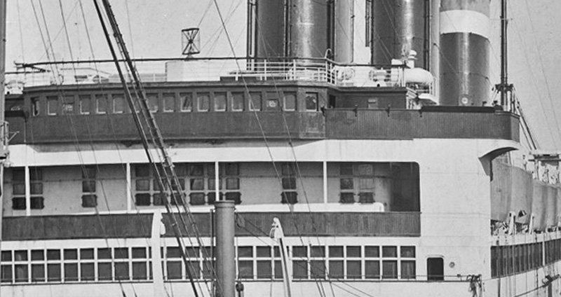
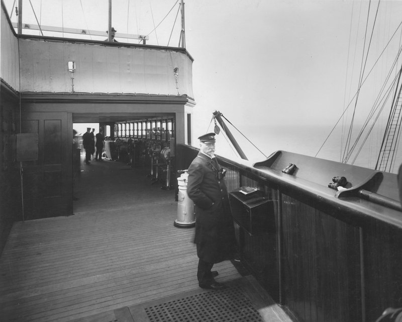
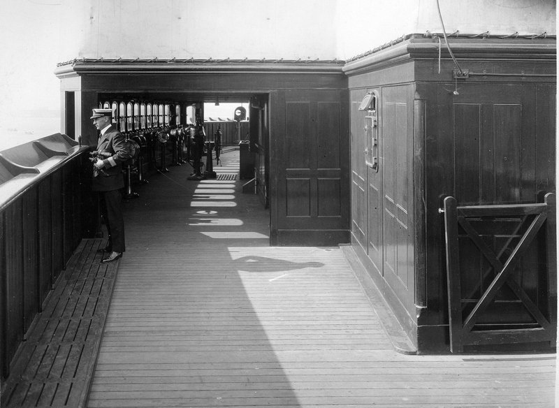
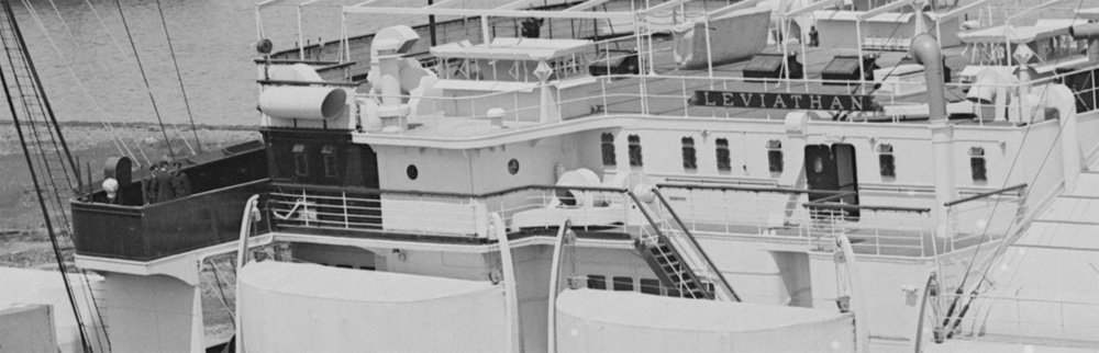
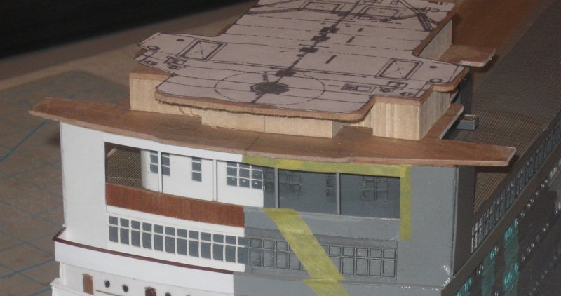
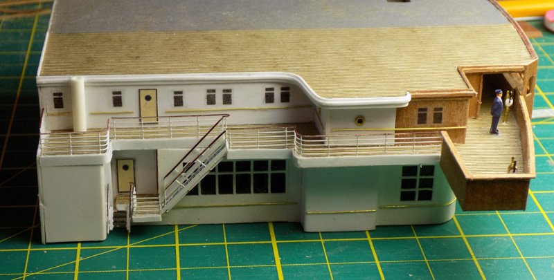
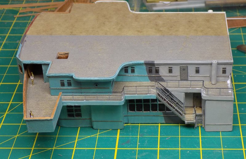
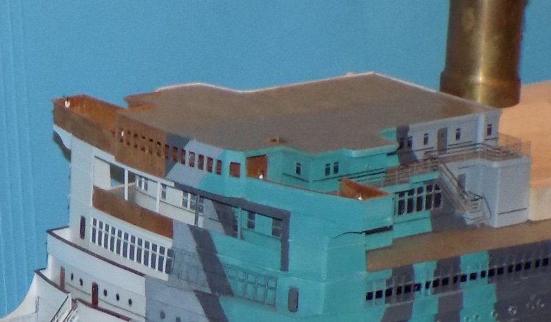
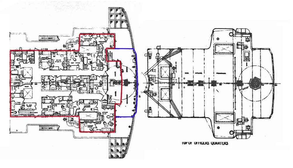
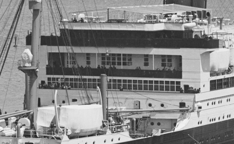
Hello to all. Thanks, as always, for the likes and compliments. I had a touch of insomnia last night, so here is the next segment. A brief one this time, and mostly pictures. On top the A Deck house is the Bridge Deck with the bridge and the officers’ quarters in its deck house. To show its elegance, the Vaterland was built with many touches of dark, luxurious hardwoods, including the bridge and the rail around the bridge wings. The bridge itself, with its many windows, juts out from the line of the bridge rail and is cantilevered over A Deck. You can see the fine woodworking in this photo of Captain Hans Ruser on the starboard bridge wing of the Vaterland. Inside the bridge are several telegraphs and other ship handling equipment including a steering wheel. Note that the wind deflector where the captain has stashed his binoculars only protects the outer part of the bridge wing. The SS Leviathan boasted the same fine finishes, restored after war duty. Captain Herbert Hartley gazes over the bow behind a wind deflector that now goes all the way to the bridge. Aft of the bridge the walls of the officers’ quarters are metal again, with a door, two portholes, several windows and some ventilation equipment. The plans are good in this area. The deck house is outlined in red. Note that it is not symmetrical. There is a stairway up to the roof only on the port side. The area of the bridge is in blue. The top of the officers’ quarters is a bit complex, but not too big a challenge. I left some extra meat on the front edge so I could refine it to exactly match the curve below. Here are the two pieces from a bit earlier in the build when their shapes were still being refined. I got caught up in the building process and forgot to take photos for a bit. Using my usual techniques I sheathed and decked the pieces, then added a paper door, brass portholes and handrails, and my homemade window decals. At the front the underlying basswood structure is sheathed in cherry veneer, rather than styrene, with fine cut strips as moldings. For the front face of the bridge I dipped a piece of veneer in wood hardener. When it dried it had enough strength to survive having the windows drilled, carved out, and finished with a square profile needle file. I curved it to make sure that it fit in the space that it had to fill before doing the final trimming. The Bridge Deck was carefully positioned on top of the A Deck house and glued down. The bridge face was installed, along with two angled single window panels. Caprails along the bridge wings were fashioned and installed, along with two cast pewter telegraphs from Bluejacket. A steering wheel was put inside the bridge, but it is almost impossible to see. For some reason Captain Hartley is dressed as a railroad conductor, but he does add a sense of scale to the area. Photoetched railings were added to the Bridge Deck at this point. I do not think that I will be working much in this area any more, and it would be more difficult to put them on once the subassembly was added to the model. The troop ship side was done the same way, with the camouflage paint laid on before detailing. After double and triple checking that everything was done the assembly was installed on the model. Supports were added under the outer ends of the bridge wings as seen in the photos, and it is now ready for final detailing. Thanks for following along. More soon. Dan
- 238 replies
-
- 19
-
-
- leviathan
- troop ship
- (and 2 more)
-
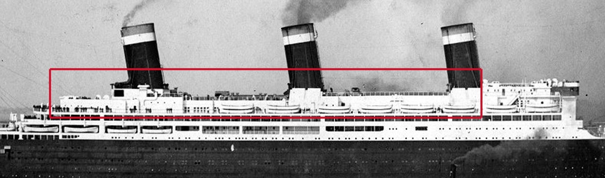
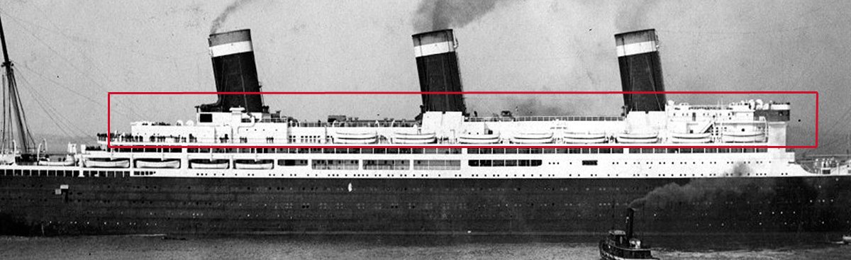
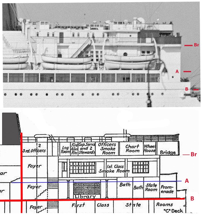
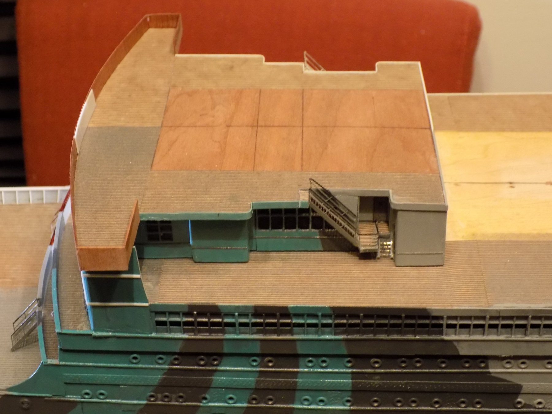
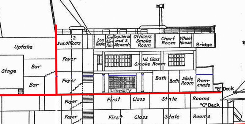
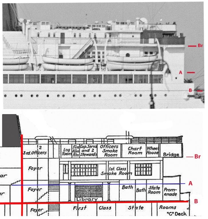
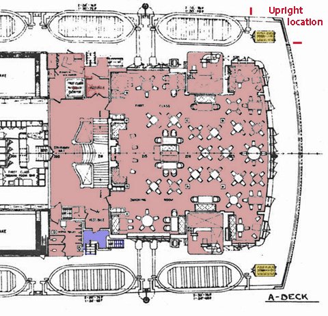
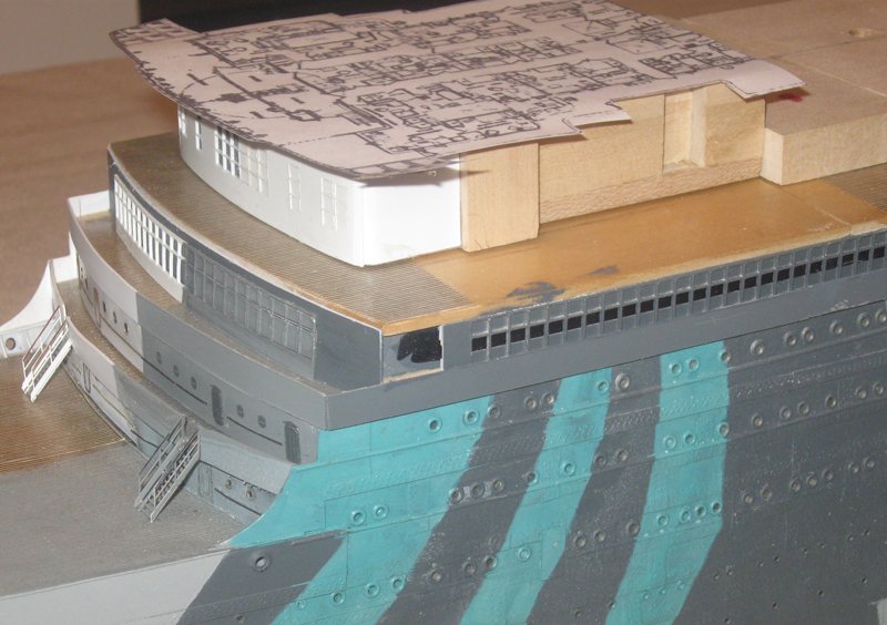
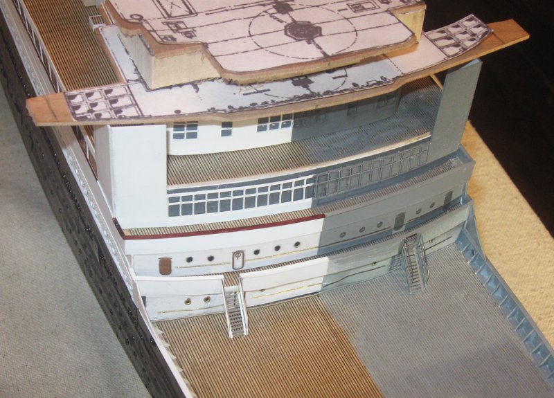
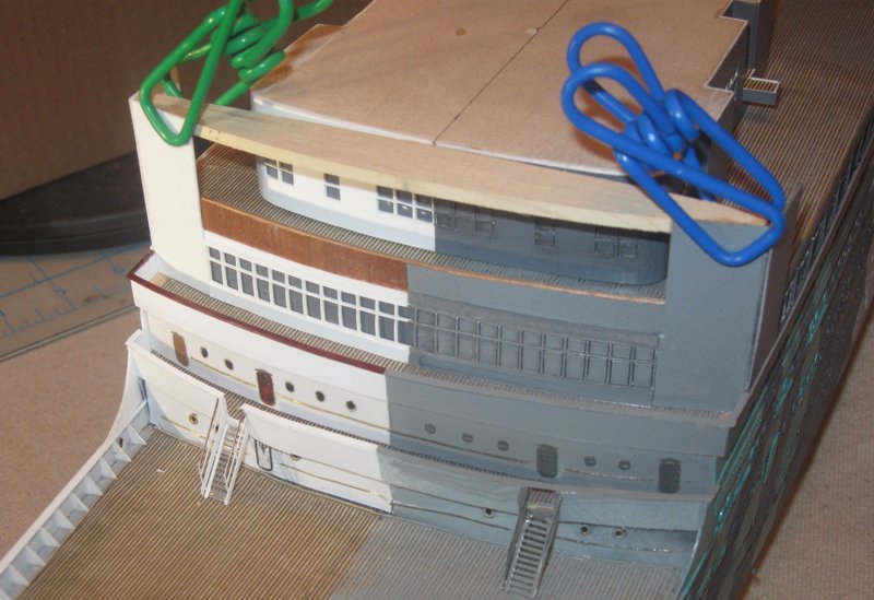
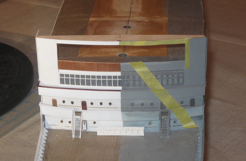
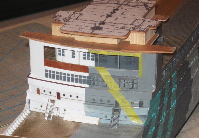
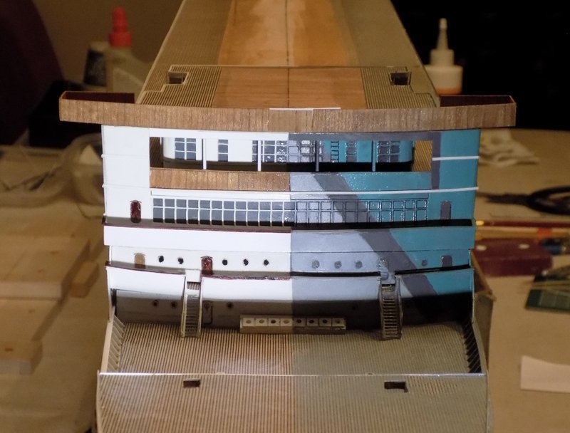
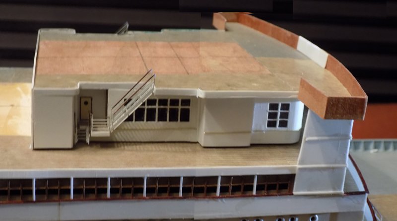
Hi Nils - and all who are following and liking what I have been posting. Sorry I have been tied up for a bit with personal matters and my writing time has mostly been taken up with the QAR articles for the Journal. Anyway, here is the next segment. Continuing the build up from where I left off, the next level to be addressed was A Deck, highlighted in the photo. As can be seen, this is a highly complicated and multi-level construction which is visually very important to the model since there is no covering deck above it. The tall superstructure forward of the first funnel is the most intricate and its position is the most critical since it has to match exactly the structures already in place. The aft end of the deck house aft of the third funnel could be off by a small amount without anyone the wiser, but not this area. So although I would have preferred to start with a simpler area, the forward superstructure had to be tackled at this point. This turned out to be one of the trickier parts of the build. At the forward face there is a large opening in front of the recessed A Deck house with a dark solid railing, which turned out to be made of wood. Four round pillars support the Bridge Deck, with large boxy uprights to either side that support the bridge wings. Judging from the heights of the people, the A Deck house is much taller than the B Deck house, but exactly how tall is difficult to determine. The plans gave me good news and bad news. In the cross section view I realized that the entire unit could be built separately from the rest of the ship. There was a natural separation above the B Deck line and forward of the first funnel. But within this area both the Library and the 1st Class Smoke Room are taller than the rest of the decks. I had a lot of difficulty in figuring out how this would work with what had already been built. Using one of these rooms as the height of the deckhouse would not be tall enough, and using both would be much too tall. Using Photoshop I compared the plans to the photo of the ship. The top of the B Deck windows that had been already constructed gave me the level for A Deck, as indicated. But on the plans there was no corresponding deck line, so I drew it in blue. Now it was clear that the Library room actually extended up through A deck and this extra height was added to the height of the Smoke Room to make up the full height of the deck house. With the height of the deck house determined I could fit the rest of the features to it. The shape of the deck house is highlighted in red, although I later determined that the area in blue is actually a landing that is outside of the main structure of the deck house. The uprights at the front are revealed to be hollow, that is, they do not have any supporting structures within them, just a stairway leading down to B deck. Combining all of this information with examination of more photos I made final plans and started cutting wood. To the basic ½” deckhouse height I added 3/16” on top to make up the added height of the Smoke Room and an additional 3/16 below for the top of the Library. This was cut and assembled before the forward face was sheathed with a set of laser-cut windows. The paper pattern for the Bridge Deck was cut and used to test its relationship to the shape of the deckhouse. Now the side uprights could be cut and installed so they matched the height of the deckhouse. This was tested against the Bridge Deck plate and the initial shapes of the upper works. You can also see how the windows were taken out on the liner side and mounted on a grey background. On the troop ship side the windows were left in, since photos of the time show that they were covered like the lower windows to prevent light giving away the ship’s position. To stabilize the uprights I fashioned a piece that would be hidden under the Bridge Deck and by the overhang in front. The solid railing was made from cherry veneer with the grain oriented vertically to simulate wainscoting. A narrow wooden caprail was cut from veneer, curved, and installed on top. The deck house was still removable and by doing so I could judge how this front face compared to the various photographs. With some minor quibbles I was satisfied. Holes were drilled through the upright support piece and the four pillars made up from bass rod and installed. The Bridge Deck plate was trimmed to final shape to match the finished structures below and the rough structures above. It was secured to the top of the deckhouse, but not yet to the uprights and their support. On the troop ship side the masking for the camouflage paint was laid on according to the photos. The camouflage was hand-painted across all the deck levels up to the Bridge Deck. I did forget to add the horizontal moldings before painting, but they will be colored later. The Bridge Deck plate has had the deck paper laid on and has been edged using my usual techniques. Across the front and around the bridge wings a solid wooden railing has been installed. The sides of the deck house were sheathed and laser cut windows installed as seen in the photos. A stairway was installed from the Bridge Deck to a landing which sits at the height of the top of the Library with a short stairway down to A Deck. Handrails were fashioned and installed since it will be hard to get to this area once the piece is installed permanently. On the troop ship side the painting was continued around as indicated in the camouflage plan, the painting and the photos. At the front of the railing is a white plastic reinforcement, but this will be hidden inside the bridge in the finished model. My next post, which I hope to get to soon, will cover the bridge and the deckhouse which contains the officers’ quarters. Until then, be well. Dan

- 238 replies
-
- 19
-
-
- leviathan
- troop ship
- (and 2 more)
-
Hi Johann - Beautiful work on the servings and turning in the thimbles in the pendants. Are you going to tar (blacken) them or leave them the tan color? One suggestion, if I may - I found that when I seized the head of the pendants and shrouds too closely to the masthead, the total bulk of the seizings of all of the shrouds would not go through the lubber's hole in the tops. I had to redo them so the seizing was below the top so I had some flexibility. I do not know if this problem will arise for you, but you should be aware of it early. Best of success on the project. I will continue to follow along with interest. Dan
-
Hi Siggi, Druxey and Mark - I am greatly enjoying your discussion. To add my two cents - The one consideration that has not been mentioned yet is how the gun would act during recoil. If the rope is fixed around the cascabel, either by a loop and a seizing or by a cont splice, then if the gun is anything but exactly perpendicular to the bulwark, the shock of the recoil will be taken up unevenly, leading to a torque on the rear of the barrel, which could not be good for the gun or the gunners. In extreme cases I guess it could overturn the carriage. Leaving the breaching rope to run free, whether with a loop or without, would even up those stresses. Dan
-
Hi Marc - Very realistic wood effects. I have used similar techniques, but your method gets very close to perfect. Druxey - would the lower deck be where the discharges for the bilge pumps would be? No need to pump water any higher than needed. Dan
- 2,699 replies
-
- 3
-
-
- heller
- soleil royal
- (and 9 more)