HOLIDAY DONATION DRIVE - SUPPORT MSW - DO YOUR PART TO KEEP THIS GREAT FORUM GOING! (89 donations so far out of 49,000 members - C'mon guys!)
×


Dr PR
-
Posts
2,446 -
Joined
-
Last visited
Content Type
Profiles
Forums
Gallery
Events
Everything posted by Dr PR
-
 Elia, The .heic photo you posted didn't open. It is best to include the photos directly in your posts. JPEG format is good for this. And welcome back. I like schooners so I will be watching.
 -
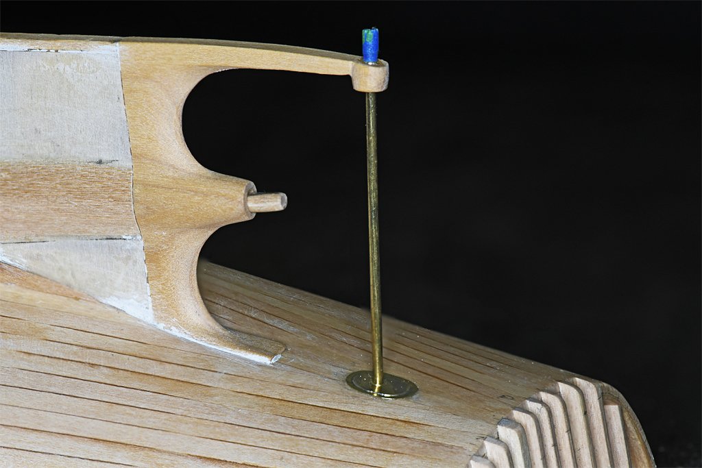
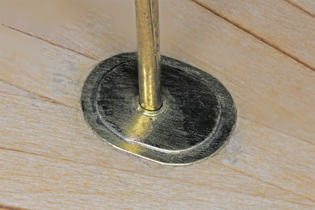
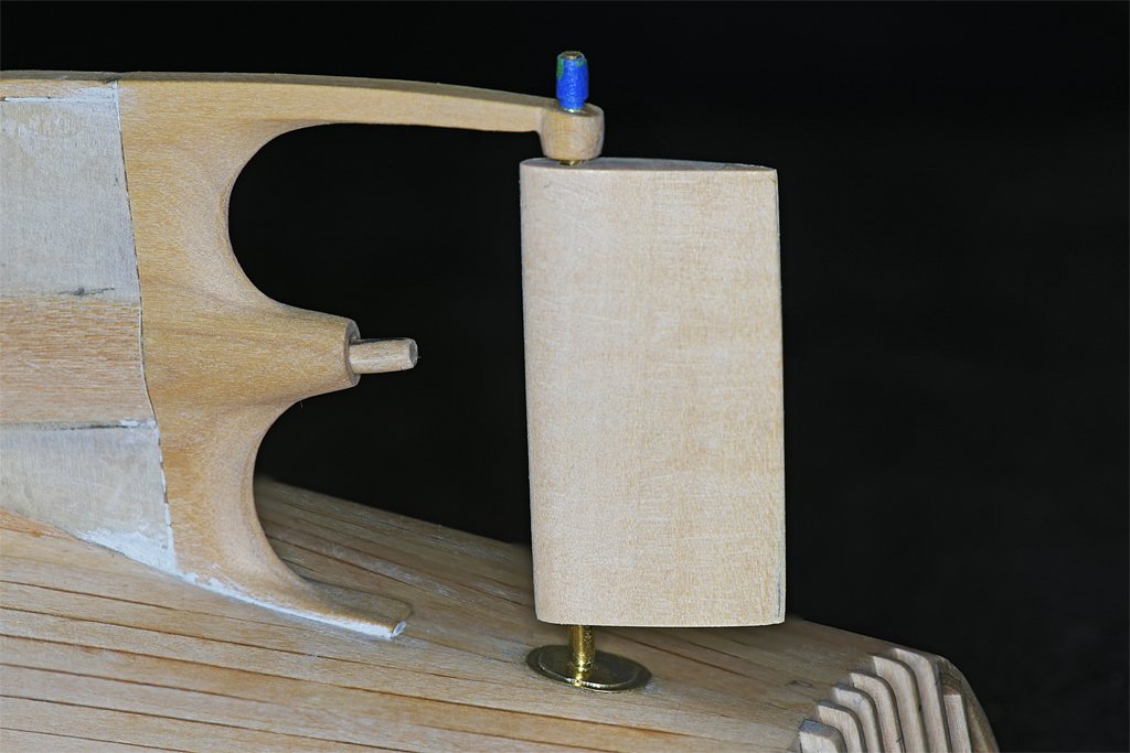
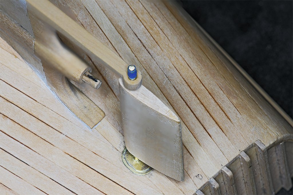
I have been working on the rudder. It is pretty simple but did require some careful work. First I cut and glued short pieces of 3/32 inch (2.38 mm) brass tubing into the hole in the hull planks and the hole in the end of the stern frame arm. These serve as bushings for the rudder shaft, and also as reinforcement for the wood in the stern frame arm. The 1/16 inch (1.59 mm) brass rod slip fits into the brass tubing. The rod is the shaft for the rudder to rotate on. After all the work is finished the part at the end that is wrapped in blue tape will be cut off. The rudder shaft passed through two concentric fairing plates where the shaft opening entered the hull. I cut the two pieces from 0.005 inch (0.127 mm) brass sheet. These were soldered together to make the assembly. The hole in the fairing slipped over the 3/32 inch brass tube and was glued in place with Duco Cement. A thin stainless sheet with a hole slightly larger than the tubing was slipped over the tube. This served as a shield to protect the fairing and hull as the tube was sawed off and the end filed smooth. The rudder was next. Two pieces of 3/32 inch basswood were cut and a groove was filed into each where the rudder shaft should be. They were glued together (Duco Cement) and the glue allowed to harden. Then a series of successively larger drill bits were used to drill out a 3/32 inch hole through the piece. I used a template with the outline of the cross section of the rudder on it to guide sanding the wood into the proper hydrodynamic shape. Then a longer piece of 3/32 inch brass tubing was cut to length to slip fit between the brass bushings in the hull and stern frame. This tube fits through the hole in the rudder and serves as the rudder shaft. But actually the tube just rotates around the 1/16 inch brass rod. The tube through the rudder also serves another purpose. It is a tight fit between the bushings in the hull and on the stern frame arm. It will prevent the arm from being bent up and breaking off if it is bumped. Just a bit of insurance! The 3/32 (0.094) inch diameter tube is actually a bit undersized for the scale rudder shaft. It really should be about 0.110 inch (2.79 mm) diameter. The next larger size brass tubing is 1/8 inch (3.18 mm) and that is a bit oversize. But I think I will cut a short piece to fit over the top end of the rudder shaft and fill the space between the wood and the fairings on the hull.
- 469 replies
-
- 15
-

-

-
- minesweeper
- Cape
- (and 1 more)
-
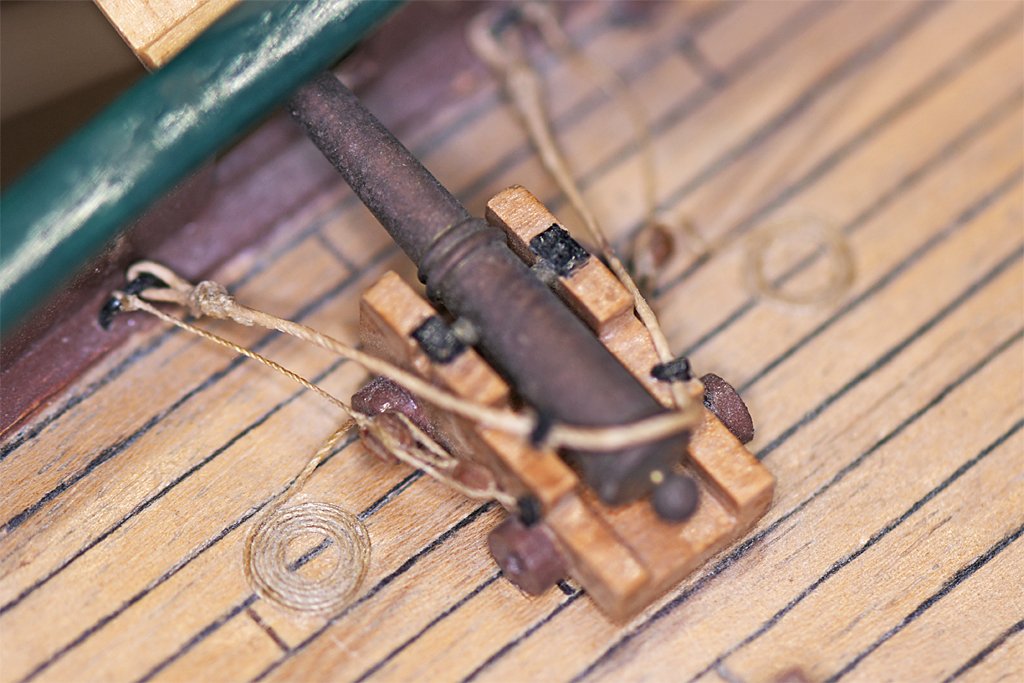
This gun was shiny brass in 1969. It hasn't been polished since. It is on a Billings Santa Maria kit - my first kit build. That is about 55 years of tarnish. If you want the guns to stay shiny spray them with clear lacquer or varnish.
-
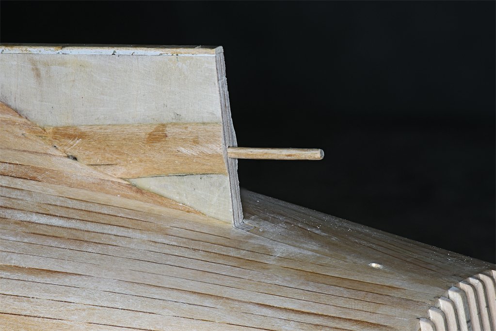
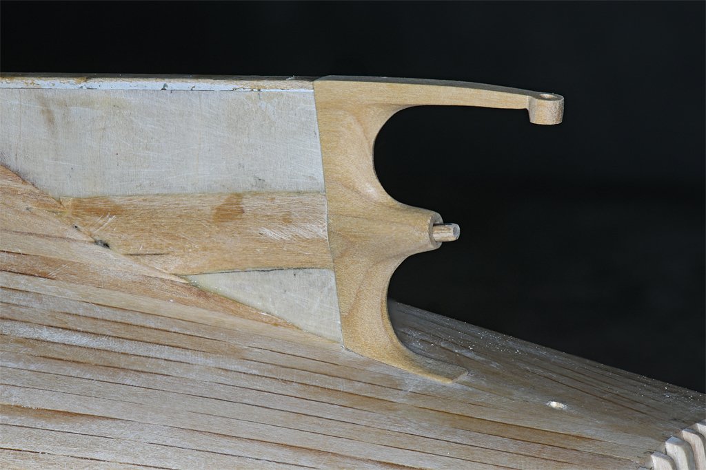
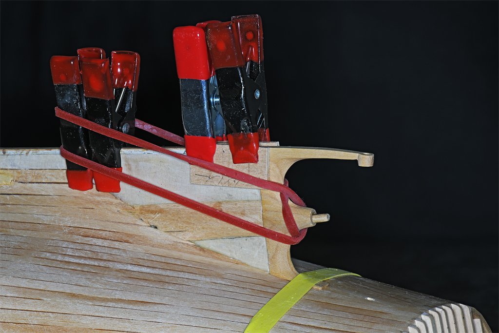
Thanks John! But here is something lovelier ... I have been test fitting the stern frame and I drilled the hole for the prop shaft. I started with a small diameter drill and carefully made the hole through the piece. Then I used successively larger drills to expand the hole to 1/8 inch (3.175 mm). Then I clamped the frame onto the hull and drilled the hole for the prop shaft into the keel/piece. To do this I made short pieces of 0.0925 inch (2.34 mm) and 0.125 inch (3.175 mm) diameter brass tubing. The one slips inside the other, and they fit inside the 1/8 inch diameter hole for the prop shaft in the stern frame. Then I used a 1/16 inch (1.59 mm) drill to start the hole - it just fits inside the smaller diameter brass tube. This produced a pilot hole in the keel piece aligned with the prop shaft axis. Then I removed the smaller piece of brass tubing and used a used 3/32 inch (2.38 mm) drill to enlarge the hole. Then the larger piece of brass tube was removed and the hole in the stern frame guided a 1/8 inch drill to finish the hole for the prop shaft. The photo on the right above shows the stern frame fitted over the prop shaft. The prop shaft is a 1/8 inch wood dowel, and it will serve as a peg to align the stern frame to the keel piece and strengthen the bond between the two. The hole in the hull below the arm on the stern frame is for the rudder shaft. The lower end of the rudder shaft will pivot on the arm of the stern frame. This is what is worth celebrating! I have glued the stern frame onto the hull. I have been dreading this because there are so many opportunities for screwing up! But actually it hasn't been all that bad. The Castello boxwood carved easily and it didn't take as long as I thought it would. And drilling the properly aligned hole for the prop shaft was fairly easy. The biggest hassle was filing down the "foot" of the stern frame that rests on the hull planks. I made it about double thickness and spent a couple hours filing it down to get the right fit on the hull. I guess that was the "worst" part of it all. The boxwood is pretty strong, but I worry about that long arm of the stern frame hanging out there just waiting for me to drop the hull or bang it against something to break that part. After I have finished shaping the stern frame piece I will clamp some strong pieces of wood along the sides to protect it. Brass would have been a better material for the stern frame but I just don't have the tools to do it correctly and in a reasonable amount of time.
- 469 replies
-
- 11
-
-
- minesweeper
- Cape
- (and 1 more)
-
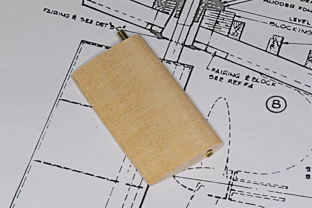
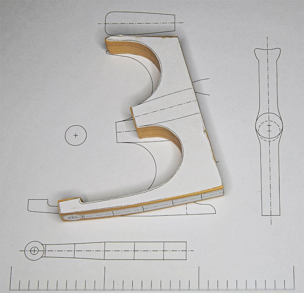
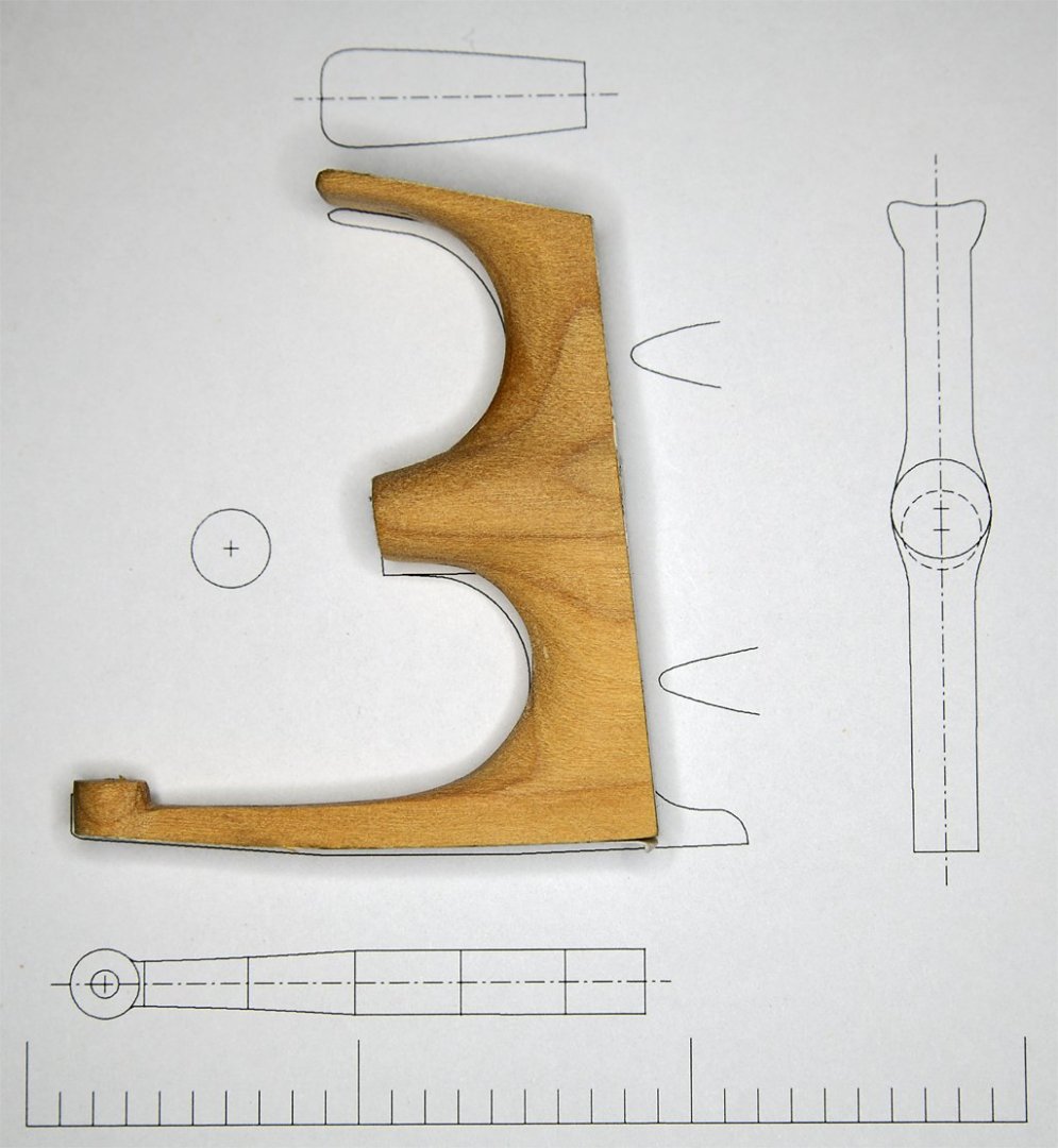
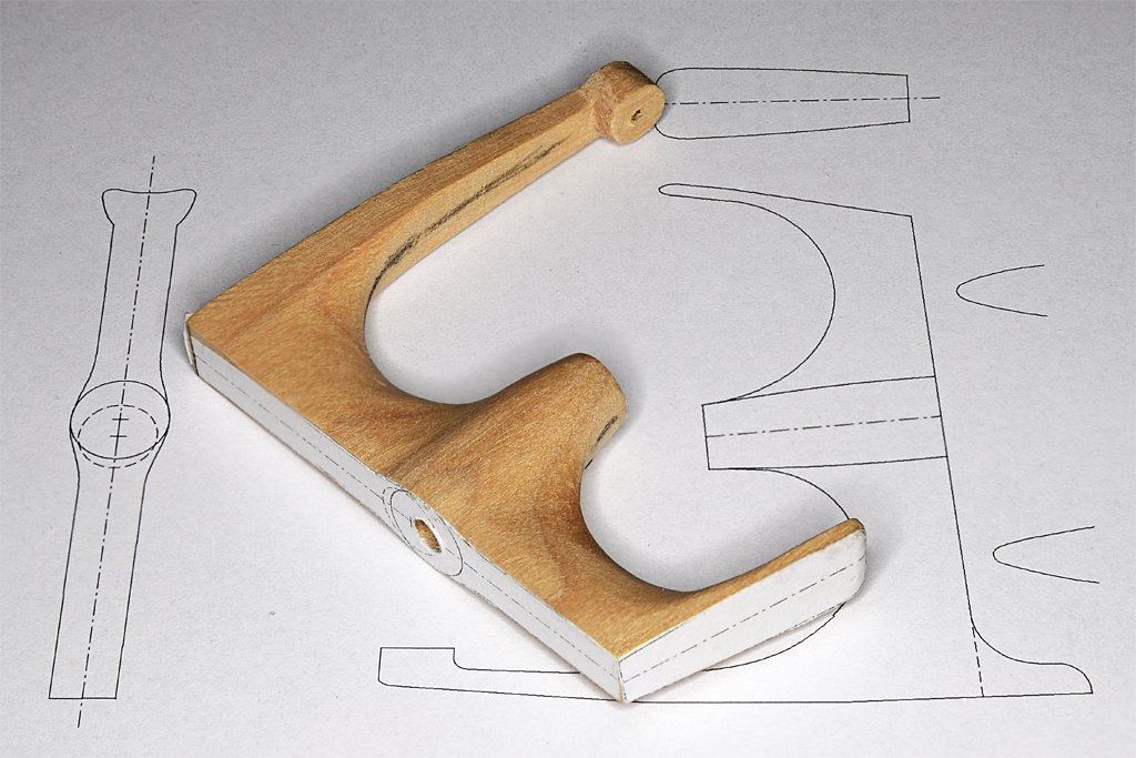
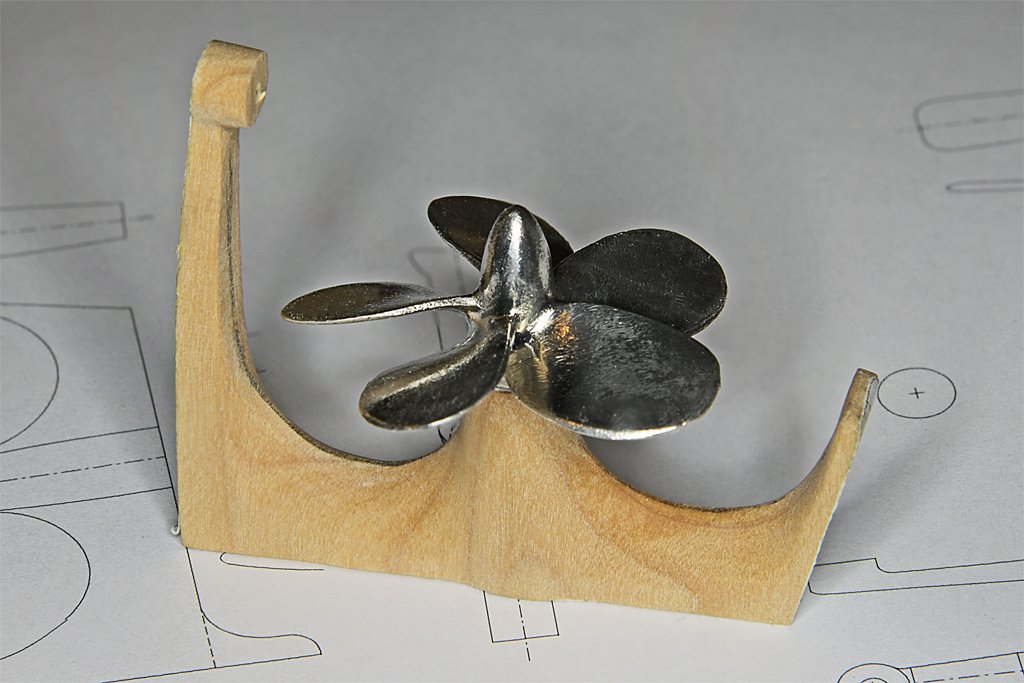
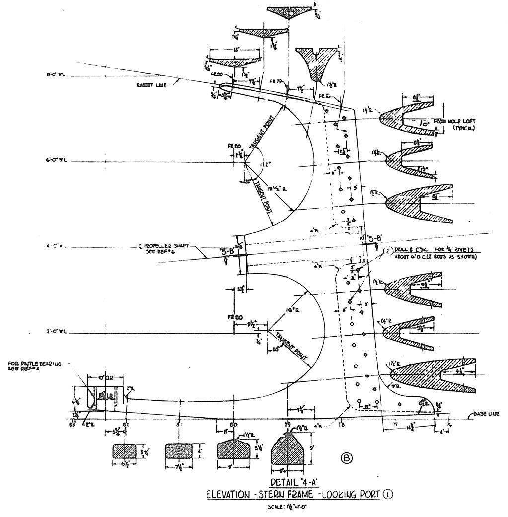
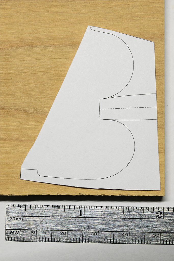
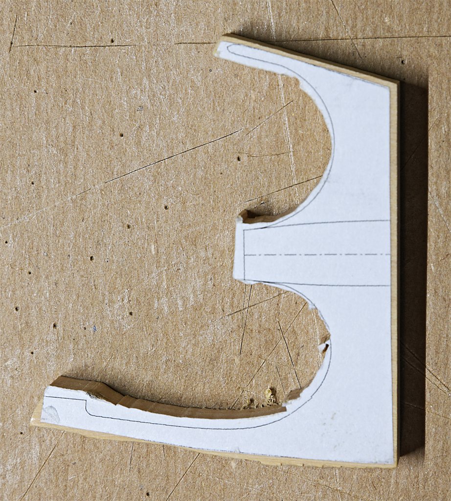
This is part of the blueprint for the stern frame. The original piece was an aluminum bronze casting. I would have liked to make it of brass, but I don't have the tools to do a good job. I have the tools and a fair amount of experience carving wood so I decided to give that a try. The nice thing about this drawing is it shows a lot of the cross sections, and that tells how to remove material from the piece. The casting had a "foot" projecting forward of the base that fit into a cutout in the keel. I have omitted this foot and cut the piece straight on the forward edge. I have never worked with Castello boxwood before so this was a learning experience. It is a relatively hard wood with fine grain. Growth rings are evident, but there was no noticeable difference in carving the darker and lighter parts. It carved easily with no chipping or splinters, and holds a fine edge. The first thing to do was clean up the rough cut piece and trim to near the lines. I also glued paper outlines of the top, bottom and ends to show where wood needed to be removed. Then I used rasps and files to cut away the unwanted wood until I had a piece of the approximate shape. I completed most of the work in an afternoon. The part shown here is still a bit oversized on all surfaces. I will wait until it is installed on the hull to file and sand the part down to be flush with surfaces on the keel/deadwood. The rudder pivots on the cylindrical part at the end of the long arm. The wide upper part will be shaped to fit flush with the hull planking. I took the advice of bdgiantman2 and got the five blade propeller from Bluejacket Shipcrafters. It is slightly oversized but fits easily in the opening formed by the stern frame. That was a LOT easier than designing a propeller in CAD and then 3D printing it! I plan to use a 1/8 inch (3.175 mm) wooden dowel as the propeller shaft. Epoxy will glue the prop to the shaft. I will use the hole in the stern frame as a template to drill a hole into the keel/deadwood of the hull. The wooden prop shaft will also serve as a pin to help hold the stern frame in place. Now I need to fit the piece to he hull.
- 469 replies
-
- 13
-
-
-

-
- minesweeper
- Cape
- (and 1 more)
-
Steve, What you are planning looks good to me. There are a couple of things I have done differently: 1. How springy is the fly tying line? I used a fine silk thread to seize lines. When it gets wet it is totally limp and doesn't try to unwind. 2. I used the white glue (Elmer's) to glue the ropes around the blocks. You want the glue to soak into the ropes. I dilute it 1:1 with water. However, the diluted glue does not make a really strong connection with the ropes. One other thing I did was make a "tumbler" and rounded off the edges of the blocks to get a more realistic look. https://modelshipworld.com/topic/19611-albatros-by-dr-pr-mantua-scale-148-revenue-cutter-kitbash-about-1815/?do=findComment&comment=981060
-
I have received the boxwood sheet that I needed for the stern frame. Here are the first steps for creating this piece. The piece cut from the 5/16 inch (7.9 mm) boxwood sheet nicely with the scroll saw. Now I will finish the carving with knives and files. This will take a while!
- 469 replies
-
- 9
-
-
- minesweeper
- Cape
- (and 1 more)
-
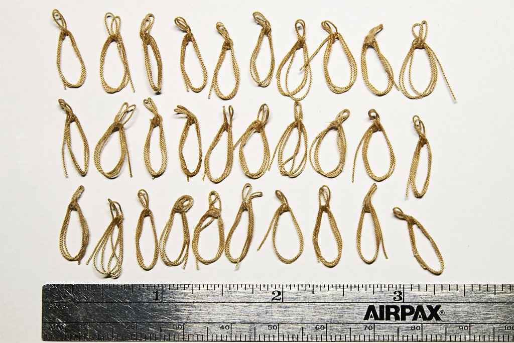
Mass production has started. Here are 37 coils of 0.012 inch (0.3 mm) rope - 30 finished and 7 in progress. The method I described above works pretty good. So far I have had 6 failures out of 36 attempts - a 16% failure rate. All of these occurred because I got into a rush and failed to follow the steps correctly. Operator error. Actually, on a few I thought I found a better way to loop the rope, and it turned out not to work. Also, the dilute white glue is a VERY weak glue and if the lines are not wrapped correctly the thing falls apart as it is being removed from the pins. However, the rope is still useable and already cut to length, so I just wrapped it again When I am on a roll I can complete wrapping a coil in about 45 seconds. But occasionally I lose control and the rope springs off the pins and I have to start over. Patience is a virtue ... I have found one slight modification that improves success. The last step before applying the white glue is to pull the long end around the pin on the right, to the opposite side of the pin from where the coils would normally wrap. This puts a bit of pull on the rope as it passes the two middle pins. I apply white glue to the side of the loop to the left of the center pins where the long end lays along the other strands to hold it in place after the loop is removed from the pins. With a bit of luck I am about half through this phase of the build. I had an "OH!" moment when I wondered if I had accounted for the 6 inches (152 mm) of rope I was using for these coils when I ordered the rope from Syren? I checked my rigging spreadsheet and I had allowed 7" (178 mm) for most of the rope coils, but only 3.5 inches (89 mm) for those that wouldn't need as many loops. So I was planning ahead. I should have over 100 inches (2.5 meters) excess rope for all the ropes used on the model! Whew!!
-
Thanks to everyone for the information.
-
Congratulations on finishing another excellent ship model!
-
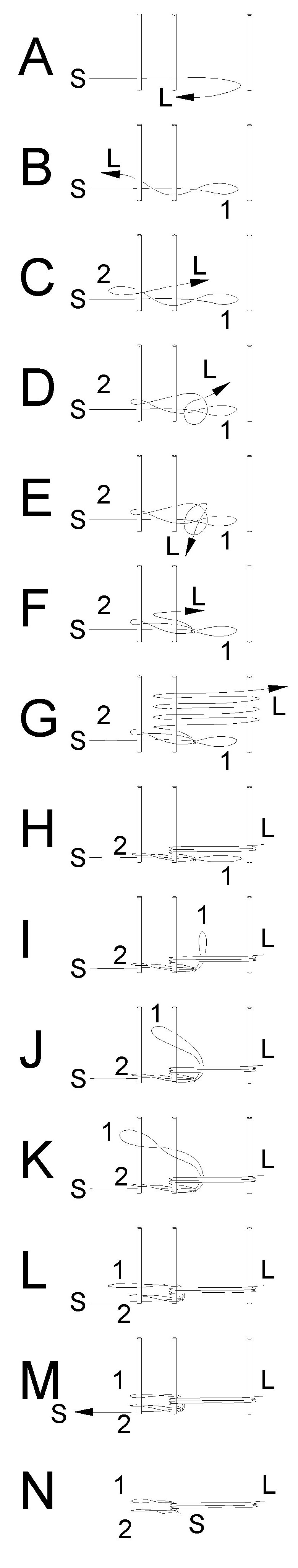
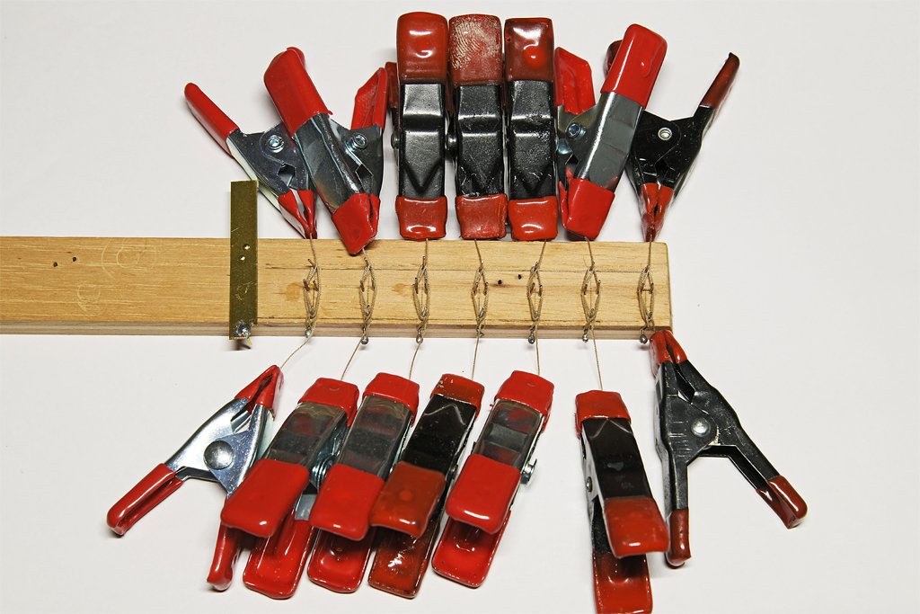
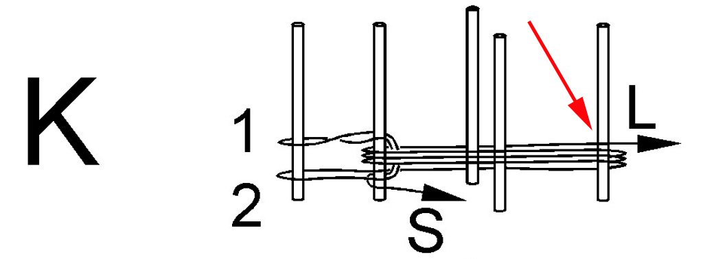
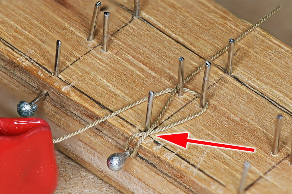
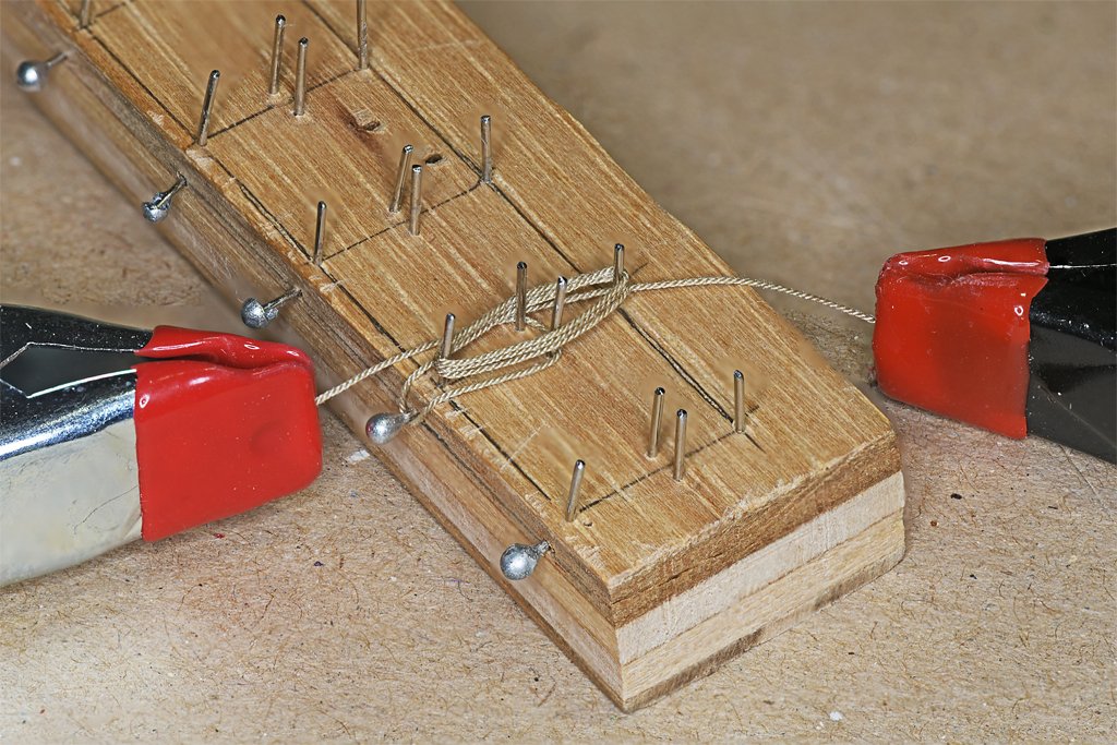
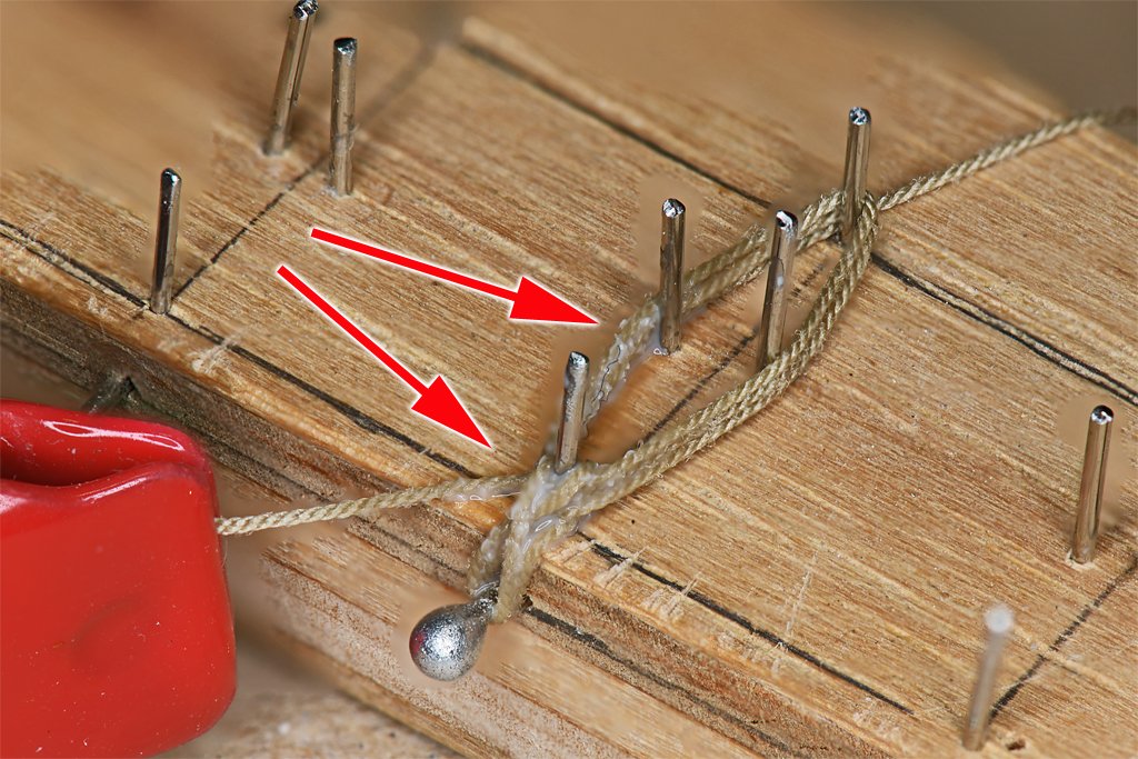
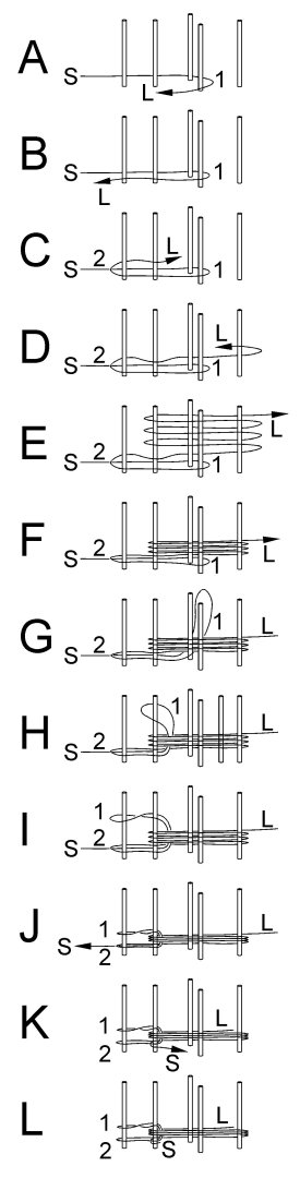
Try again, and again, ..., until you get it right! I think I am getting somewhere. I improved the technique described above, eliminating the knots. As before I have an initial loop to fit over the belaying pin and provide a fixed end to pull on, and a final loop that fits over the belaying pin to hold the rope coils in place. Here you see two coils made with the new method. They look pretty good! No bulging knots and they hang reasonably "naturally." These are test pieces made with carpet thread. I made a new tool, lengthening the distance between posts so the coils would hang almost to the deck. With the new tool I start with a 6 inch (150 mm) piece of rope and have only about an inch (25 mm) of scrap cut off the ends after the coil is finished. Here is the step by step procedure. S = the short, unmoving end of the rope, L = the long end that is wrapped around the posts. 1 and 2 are the two loops that fit over the belaying pin in the pin/fife rail. The arrows show when the ends of the rope are pulled. Be careful to not cut the short end too short! The new fixture has four pins for the rope coils to wind around, placed in an elongated "diamond" or parallelogram pattern (see photos farther down in the post). The fifth pin on the left serves as a pseudo belaying pin. A. I attach a small clamp on to the short end (S) to keep it from moving. Then the long end (L) is pulled around the two pins in the middle of the diamond pattern. This forms the start of loop 1. B. The long end is pulled to the pseudo-belaying pin (left most in picture). C. Now the long end curves back around this pin to start loop 2. It must curve back around the second pin to the left in the picture on the same side as the first leg of the loop. This ensures that loop 2 will be formed correctly to loop around the base of the belaying pin under the rope coils. D. The long end runs all the way to the right around the right most pin and curves around to start making the rope coils. E. The long end continues to wind around the four pins that form the coils until enough turns have been made for the piece that is appropriate for the rigging at a particular belaying point. Some may have fewer turns, and some may have many. F. After all the coils have been made they should be pressed down to make easy access to the end of loop 1. G. Pull the end of loop 1 up through the center between the coils. It was initially looped around the outside of the two central pins. Now it must be lifted over these pins so the "legs" of the loop are free to move inside the coils. This will pull in the short end of the rope. Be sure it doesn't pull in past the left most pin! H. Continue pulling the end of loop 1 back over the second pin from the right. This is where it hooks over the coils. I. Hook the end of loop 1 over the top of the left most pin. Put a twist in the loop as you hook it over the pin. J. Now pull on the short end (S) of the rope to tighten loops 1 and 2 around the left most pin. K. Place a drop of thin white glue on the cluster of ropes around the pin second from the left. The glue must soak into all the ropes at this point so the assembly doesn't become unwound after it is lifted from the pins. Pull the short end (S) back along the side of the coils so it will be glued in this position. L. After the glue has set you can lift the assembly from the pins. Trim the long end (L) to the desired length. Trim the short end (S) fairly close to the glued ropes, but leave a bit between 1 and 2 mm long. I find it useful to place a small drop of cyanoacrylate (CA) glue on this "tail" of the short end just to be sure it doesn't come loose. Here is a photo of the tool and a coil assembly in progress. The four pins of the "diamond" to form the coils are on the top of the tool. The middle two pins serve to open the coils and also serve to form loop 1. The "leftmost" pin in the illustrations above is the ball headed pin on the side of the tool. This represents the belaying pin. This illustrates step C showing how both legs of loop 2 pass on the same side of the left most pin in the diamond. This is important! This is a better view of the tool. I made seven "stations" so several coils can be made at a time. You can see how I use the small clamps to "tame" the rope - it wants to unwind from around the pins. This is step H after the coils have been pushed down on the tool. This is step M after the short end has been pulled to tighten loops 1 and 2 around the "belaying pin" shaft. I apply dilute white glue where the arrows indicate. I soak the bunch of ropes around the pin, and also paint some glue on the ropes down the side of the coil to glue the long end (running off the top of the photo) to the lower ropes of the coils. This prevents it from coming loose and causes it to hang down when the assembly is on the pin/fife rail. The short end is pulled off to the left side of the picture to pull it tight around the metal pin. After the glue dries the "belaying pin" is removed and the coil assembly is lifted off the pins. It helps if the pins are bent inward slightly. The coil shown in these photos was made with 0.012 inch (0.30 mm) rope. It is the first of 70 rope coils for the model.
-
Paul, The Wapama was one of my favorite museum ships. I visited it a couple of times back in the 1970s. I loved the interior woodworking, the spiral staircase to the passengers quarters, and the Captains cabin decorations. It was very interesting to go below into the engine room and get a close up look at the triple expansion steam engine. It was a crime for the National Parks Service to let it rot away! I am glad you are making this model. I have considered making one myself - for some time down the road.
-
Well George, You have come up with a puzzle there! Personally, I would go with putting the tackle pendants on first, and not last. Why? You are modelling a British ship, and the Admiralty was notoriously conservative about how things were done - and any change to the "right" way was resisted. And on their ships the mast tackle went on first. Marquardt was German and most familiar with northern European vessels - and those in Australia after he moved there. Petersson's rigging was based upon a model of the American made schooner Experiment, built in 1808 and sold to Sweden. He says the model was not an exact replica of the Experiment. Many in America followed Royal Navy standards, but each ship yard had their way of building vessels. The only certain thing I have found about rigging for sailing vessels, and especially schooners, it the it is probable that no two were built and rigged the same - not even in the Royal Navy. Ship owners, Captains and bosuns all had their "right" way to rig things. Unless you have the actual rigging plan for the Ballahoo, for the time period you are modelling it, I think you can do whatever you want with your ship! I agree with your reasoning for serving the after shroud to avoid chafing with the gaff sail. The fore course wasn't commonly rigged so it wasn't a concern for chafing the forward shrouds, and the spreader yard was usually fixed in position and not raised or lowered, so it wasn't a chafing hazard.
-
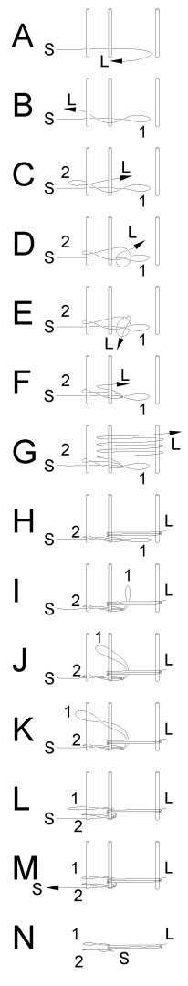
If at first you don't succeed ... The main problem I was having is that there is no line connected to the belaying pin to provide a solid point to pull on. You can see this in this video about 1 minute 15 seconds from the start. https://www.youtube.com/watch?v=awiFzE5SXzU When the fellow pulls the rope through to make the loop to go over the pin, he is pulling against the rope already tied on the pin. So I decided to start with a loop that will go over the pin first, then make the coil, and end with another loop over the pin. Note: On the tool I used to make the coils the left most pin was mounted on a surface perpendicular to the surface the other two pins were on. See the pictures in this post above: https://modelshipworld.com/topic/19611-albatros-by-dr-pr-mantua-scale-148-revenue-cutter-kitbash-about-1815/?do=findComment&comment=1084631 In this drawing S = short stationary end of the line, L = the long end that is wrapped and tied around things, 1 and 2 = the loops that will go over the belaying pin. The left most pin on the tool is the belaying pin substitute and the right two are used to make the rope coil. A. Pull the rope long end around the two pins on the left. Leave a long loop 1 to the right. B. Loop the long end around the pin on the left (a substitute for the belaying pin). This creates the second loop that will fit over the belaying pin. C. Bring the long end back over the first loop. D. Wrap the long end around loop 1. E. Make a loose knot (don't pull tight yet) between the end of loop 1 and the pin. F. Now start wrapping the loose end around the two right hand posts. G. Make the desired number of loops for the rope coil. H. Compress the loose loops into the coil. I. Bring loop 1 up through the center of the rope coils. J. Bring loop 1 up and over the the middle pin. K. Put a twist in loop 1 and pull it over the left pin. L. Pull loop 1 down above loop 2. M. Pull on the short end S to tighten loop 1 around the post. Put a drop of glue on the base of loop 1 at the middle pin (use one that won't leave a stain of shine on the ropes). N. Remove the coil from the pins and cut off the short end S. Hang it over the belaying pin. Put loop 2 on first, followed by loop 1. Pull the coils down below the pin/fife rail. Here is the result. The two coils on the right were made as described above. The far right coil was a test made with ordinary carpet thread. The middle coil is 0.012 inch (0.3 mm) rope. While loop 2 did work to provide something for loop 1 to pull against, the knot made in step E is pretty obvious. Not perfect! The coil on the left was made without tying the knot (steps D and E). I put a drop of white glue in place of the knot and when it dried I continued with the rope coils. After taking the coils off the pins and trimming the short end S the white glue failed and the end of loop 1 came loose! I glued it back on with some CA gel, but I can see here that I glued it to the wrong side of the coils!! I think the double loop approach has promise. I'll keep working on this to perfect my "technique." I'll try using the CA gel instead of the white glue to "tie the knot" in steps D and E. I think I am really going to enjoy the MSI build - it has almost no rigging!
-
George, Thanks! Note: "Pin loop" means the small twisted loop that fits over the belaying pin. "Coils" refer to the larger multiple loops that make up the bulk of the assembly. I think one problem I had was caused by wrapping the coils "backwards." In the photos I posted I started wrapping with the end that eventually was pulled up for the loop over the belaying pin. As a result the ends of the pin loop pulled up from the bottom end of the coils. That was wrong! I should have started the coils from the end hanging down loose when the coils are belayed to the pin. When this end was pulled up to make the pin loop only the hanging loose end would be shortened to get material for the pin loop and not rope from any of the coils. The real problem is that when you are belaying a real rope on a real pin, one end of the "pin loop" is already secured around the pin, so when you pull it tight it comes up and around the loops in the rope coil. But with the way I did it there is no way to pull the pin loop tight around the rope coils. So it falls apart! I like your idea of securing the first loop in the coil with a knot at the end where the pin loop will be made. The knot will be covered by the other loops. When the pin loop is pulled up the knot will prevent it from pulling rope from any of the coils. It will be a couple of days before I get a chance to implement your method, but thanks for providing it! PS: Happy Mozart's birthday.
-
This is developing into a very pretty model!
-
John, The ropes on your Bluenose look great! The reason I want to make separate rope loops and not try to make the loops in situ is that on this model there are 70 of them. There are too many lines crowding around the pin rails and fife rails to allow the access I need to tie them in place, especially with the sails in the way. It is going to be difficult enough just to tie off all of those lines on the crowded pin rails.
-
vw, So true! Now I just need to come up with plan B!
-
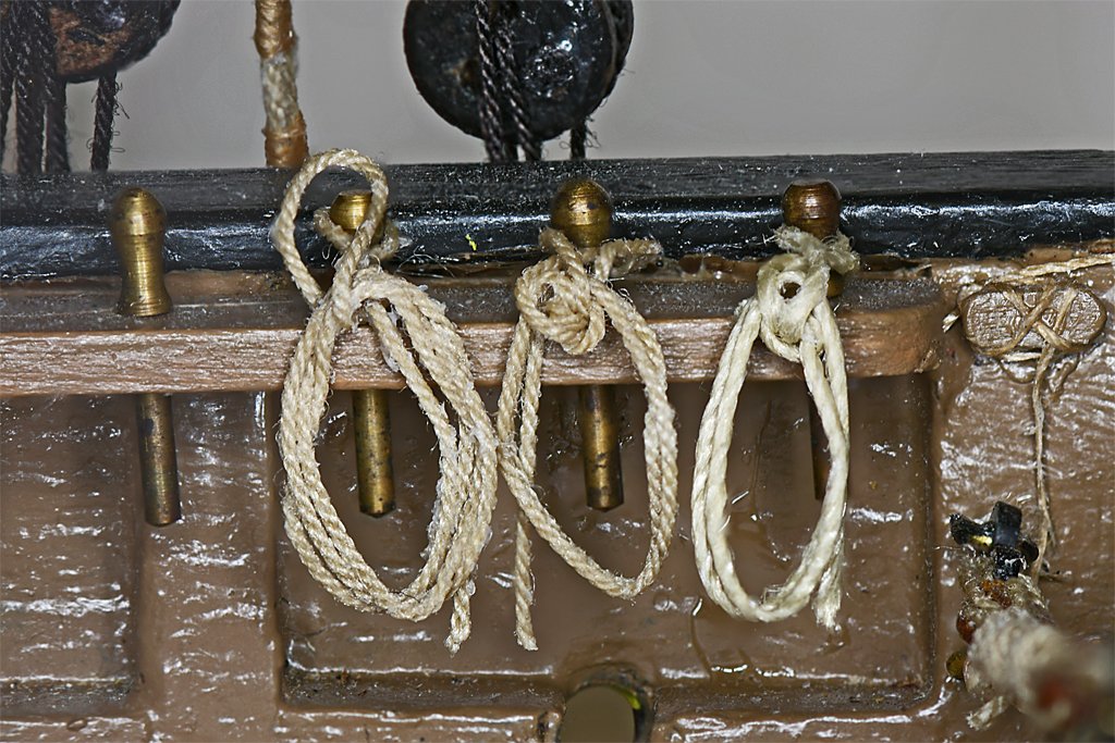
wefalk's comments bring up the question - what were these beams used for? Why were they there? In your last photo the boat is resting securely in chocks, and it is held down with chains. It looks like it isn't going anywhere, no matter how rough the seas.
-
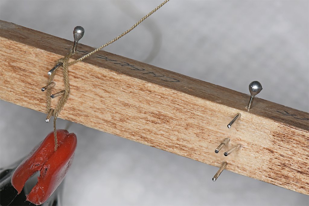
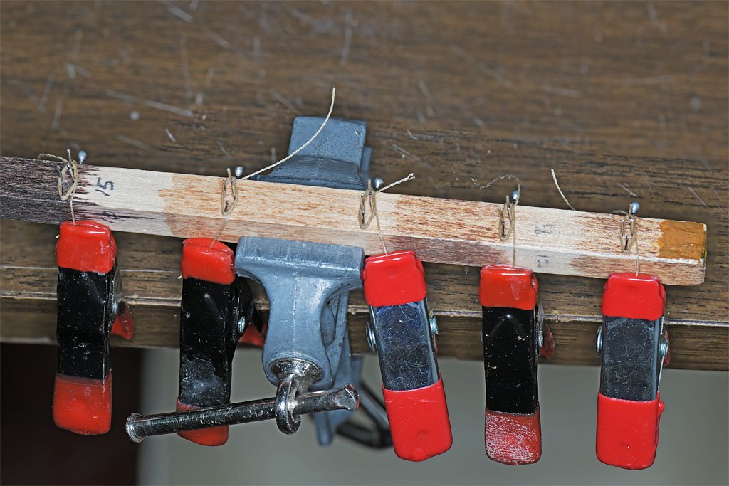
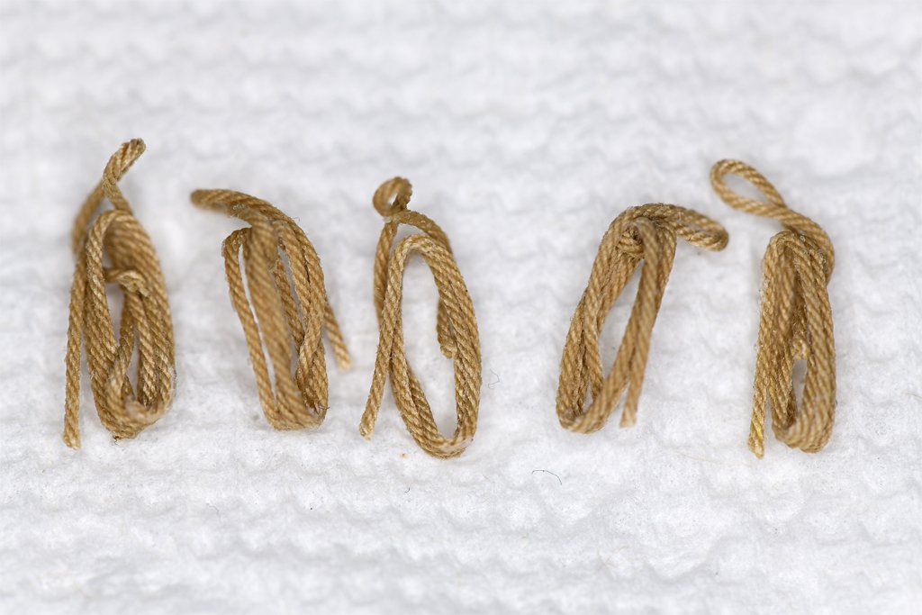
I will need a couple dozen rope loops of different sizes to hang on the pin rails after all the lines have been belayed. I read through the topics posted in the Masting Rigging and Sails section of the Forum, and came up with a simple way to make these loops. There were several different methods for making rope loops, but most involved looping some rope around pins, pulling out part of the first loop, and hooking it over another pin with a twist. I used a scrap piece of wood that had been used to test different stains. Straight pins were hammered into holes in a diamond pattern, and then the tops of the pins were cut off. The spacing was designed to make loops that would just touch the deck when hanging from belaying pins. The single pin "around the corner" from the loop pins is for the rope "eye" for the belaying pin to fit over. It is removed when the loop is taken off the fixture. You can see the basic arrangement on the right, and a loop in progress on the left. After the rope loop was completed it was soaked with white glue diluted 1:1 with water. The fixture has five sets of pins to allow "mass production" of the rope loops. The loose end from the first loop that makes the eye for the belaying pin will be trimmed off after the glue sets. The other end is pulled taut by the clamps while the glue sets. Then it is trimmed to about the bottom end of the loop. Here are five loops made with 0.025 inch (0.63 mm) rope (left). On the right they are hanging on pins in a pin rail. These suck! The eye that fits over the belaying pin doesn't wrap under the bundle of rope as it should, and it comes off at an odd angle, and not right at the top of the loops. This causes the loops to hang at an odd angle, and too high. When I tried to pull the loops down to a more natural position the glue failed and they unraveled into a rats nest of lines! It was a waste of good rope! Punt! I am going to have to come up with a better way to make rope loops. If anyone has suggestions I am "all ears." Note: In past builds I have rigged the lines and then belayed them on the belaying pins, with sufficient extra line to loop them and tie them off as it is actually done on real ships. Those loops looked really good.
-
George, If you want to make the pictures smaller just double click on them after they have been placed. You can change the dimensions - be sure to check the box to keep the same X/Y proportions. If you want to place two pictures side by side, make the first one left justified and leave the second one with no justification. If you make a picture left justified you can place text to the right of it. If you use no justification text will start below the picture.
-
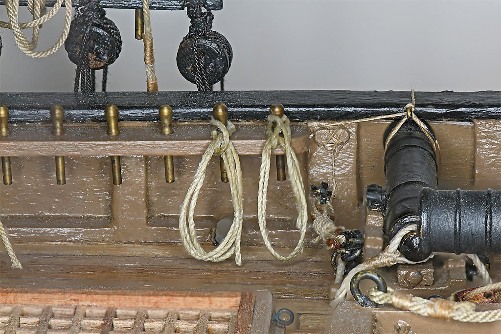
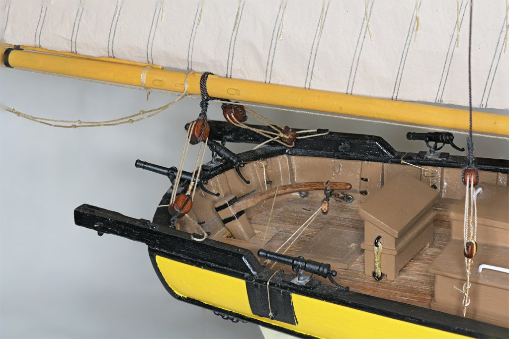
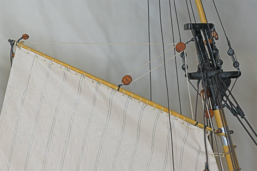
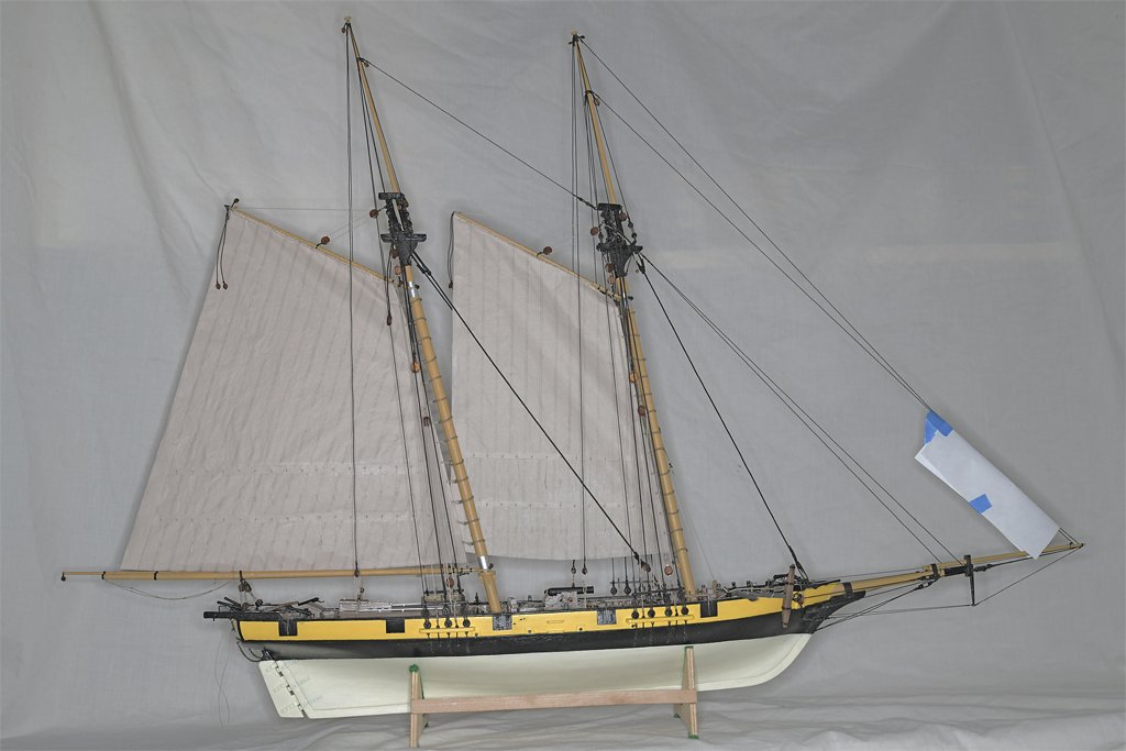
Thanks John! One more done. The main sail is the most complex sail. In addition to rigging to the gaff and mast hoops, it also has the main boom rigging to deal with. The sail is "loose footed," and is not laced to the boom. The tack is tied to a ring bolt on the top of the boom jaws. The clew has the sheet rope attached to the cringle. The sheet runs through a sheave at the end of the boom and then forward to where it is stropped to a single block. A double block is tied to a ring bolt on the bottom of the boom jaws. These blocks form a luff tackle for the sheet, with the fall tied to a cleat on the port side of the boom. The boom is supported at the forward end by the boom rest on the mast. The aft end is held in place by the boom sheet tackles. Most drawings show the lower double blocks hooked to eye bolts in the deck. I rigged them to eye bolts on the bulwarks, with the falls tied to cleats (not fully rigged in these photos). If the blocks were hooked to eye bolts on deck the tackle would fall on the tiller when the boom was swung outboard. And if the crew ever did haul cannons back to the stern chase ports the boom tackle would interfere with the cannons. So I rigged the tackles high. There are eye bolts on the deck where the tackle also could be rigged. The gaff is rigged pretty much like the fore gaff. The block sticking up above the aft end of the gaff is for the sheet of the spar gaff topsail. A smaller block is also hanging from the end of the gaff - it is for the flag halliard. I designed the masts, spars and sails in 2D CAD drawings and used the measurements to lay out the sails and calculate the lengths of the rigging ropes. But the proof is in the pudding they say. I was pleased to see that things ended up in their intended places after everything was rigged. In particular, the gaff jaws are riding on the metal sheet on the mast, while the boom jaws are resting on the boom support. And the gaff throat halliard tackle hangs nicely and is not two-blocked. Sometimes the best laid plans do work! There are a number of lines still to be rigged. Port and starboard topping lifts will attach to the end of the boom, then run through single blocks on pendants hanging from the crosstrees, and down to single blocks that are part of a running tackle. The standing parts of the running tackles fasten to eye bolts on deck just aft of the pin rails. The falls belay to pins in the pin rails. Like the fore sail, the vangs have not yet been rigged, nor has the flag halliard. I rigged the gaff sails before the higher sails so the running rigging from the other sails would not be in the way of tying the sails to the mast hoops. But this created another problem. The sails block access to the pin rails from the opposite sides of the ship, and this makes it harder to tie ropes to the pins. It still can be done, for I have belayed the throat and peak halliards of both gaffs to their respective belaying pins. But it wasn't a simple exercise. There are 26 more ropes to be tied to these pin rails, and it will be a test of my patience!
-
Peter, Access to belaying points is a problem! I started by installing the gaff sails (foresail and main sail) because the rigging for all of the higher sails would be in the way of attaching the luffs of the gaff sails to the mast hoops. The standing rigging lines created enough obstacles as it is. However, now that these large sails are in place they block access to the pin rails on the bulwarks! I have a method of looping the lines under the rails and around the base of the pins working from the outboard side of the bulwarks but it is tedious. It would be a lot easier if I had clear access from the opposite side of the ship from the pin rail.
-
Ian, Nice work. This may be your first sailing ship build and the most complicated thing you have modeled, but your prior modelling experience shows. You are doing a very good job - especially for your first hull planking!