Dr PR
-
Posts
2,456 -
Joined
-
Last visited
Content Type
Profiles
Forums
Gallery
Events
Everything posted by Dr PR
-
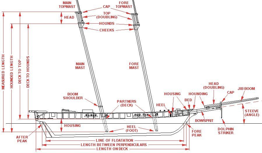
The meaning of "mast length" depends upon the author, and unfortunately most seem to think you can read their minds. Lees is no exception - at least I can find no place in the book where he actually states a definition of mast length. However, by comparing his tables to some of the drawings it appears he means the total length of the mast (measured length) from the heel (step, foot) or very bottom of the mast to the top of the top cap. Many authors use the "hounded length" for mast length, and one I came across used the length from the partners (deck) to the top of the top cap. When some say the "top" they are actually referring to the bottom of the doubling (the hounds) but most mean to the top of the top (doubling), or top of the top cap. The term "hounds" is another vague term. Some authors say the hounds start about 2/3 the distance from the deck to the cross trees, others say it includes the cheeks, and yet others say the hounds are the bottom of the doubling where the cross trees are supported. And "hounding" means the distance from something (deck, foot) up to the hounds, whatever they are. All the confusing, contradictory and conflicting definitions that people use - and assume everyone else knows exactly what they mean - gave me the greatest problems when trying to research how sailing ships were built. The meaning of many terms changes with time, so you have to know the period an author is talking about. You must never take any meaning for granted, and if authors do not say specifically what a term means, you really have no idea what they are talking about. Here is a drawing I made up to explain a lot of the terms used for ship's dimensions: Since you are new to all this, remember that rope dimensions are usually given as circumference unless otherwise stated to be the diameter. But masts and spar thickness is always given in diameters.
-
If you really want to get into the details get a copy of "The Young Sea Officer's Sheet Anchor," Darcy Lever (1808) and George Blunt (1858), Algrove Publishing Limited,Ottawa, Canada, 2000. The first part tells how to rig a ship and the second part tells how to sail a ship. It has an enormous amount of detail and information on ship handling.
-
If you decide to look forscale rope to match the ship type and size you might want to look at this thread I started on topsail schooner rigging. https://modelshipworld.com/topic/25679-topsail-schooner-sail-plans-and-rigging/?do=findComment&comment=750865 I have attached a spreadsheet for schooner mast and rigging sizes. Mast spar and rigging calculations.xlsx
-
Dave, I kept thinking Endeavor sounded familiar to me. When you mentioned the AOTS book I had one of those "duh!" moments. Sure enoough, I picked up a copy at a used book store years ago and it has been collecting dust on the shelf! The book shows studding sails outboard the course and topsail on the fore and main masts. There was a "driver" similar to a studding sail on the end of the gaff on the mizzen mast. The Anatomy Of The Ship book "Captain Cook's Endeavor," Karl Heinz Marquardt, Naval Institute Press, 1995. It is very well illustrated with a tremendous amount of detail. I recommend you get a copy if you can find it. If I can answer any questions from it for you just send me a personal message.
-
Dave, I am not familiar with the Endeavor so I suggest you find whatever you can that was published about the ship. But here is a guess as to why there were no studding sail booms on the topsail yards. First, the boom spread the foot or bottom of the sail. The top of the sail was laced to a (relatively) small studding sail yard which was hoisted to the end (yard arm) of the spar above. So if you have booms on the course (lowest) yards they are for studding sails that are raised outboard of the topsail. The booms stowed on the channels hooked into fittings on the hull or channel, and were used to spread the lower studding sails outboard of the course (lowest sail) and the studding sails were raised on studding sail yards that were hoisted to the yard arms on the course yards. This arrangement would provide studding sails for the lowest two spars on the mast. I would guess that there were no studding sails for the topgallant or royal, if the ship had these sails. Therefore there would be no studding sail booms on the topsail or topgallant yards. Mark's comment about changing tack must be spot on. There were enough other lines and sails to be messed with. Raising and lowering studding sails would have added a lot of work. One thing to remember about sailing ships is that nothing happened very fast. Eight to ten knots was a good speed for most ships (but clippers often moved twice as fast). Changing tack took quite a bit of time, especially on merchantmen with small crews. So the studding sails would be used only when the wind was right and the ship would be on the same tack for quite a while. Period paintings often show studding sails rigged only on one side. For what it is worth, I knew little about sailing ships when I started modelling, and I still know a lot less than some of the "old salts" on this forum. But I am learning, and that is a big part of the enjoyment of model making for me!
-

sail plan for Ballahoo (Fish class) topsail schooner
Dr PR replied to georgeband's topic in Masting, rigging and sails
Wefalck, Good point about the hull shape determining the type of ship and not the rigging, at least before the early 1800s. Also a good question about the flying jib. There is some ambiguity about the term "flying jib." Lees (page 126) says it was introduced after the "flying jibboom" was introduced (but doesn't say when). He states further that it was secured to the "flying jibstay" with hanks. So in this case "flying" does not mean hoisted without attachment to a stay. But he is talking about English square rigged warships, and there is little of anything in his book about schooners or other small craft. Marquardt (page 181) says the jib and flying jib can be rigged to a stay or set flying. He says the jib boom was introduced about 1695 and became official in the Royal Navy in 1705. He doesn't mention a flying jib boom. So perhaps a "flying jib" precedes the flying jibboom. Mondfeld (page 226) says the flying jib boom was introduced in the late 18th century. So that puts the advent of the flying jib as likely sometime in the 1700s. I looked through Chapelle's "The Baltimore Clipper" for examples of a jib or flying jib set high. On page between 70-71 there is an image of a watercolor of the hermaphrodite brig Diomede ,built in 1809, with what appears to be two sails on a stay from the end of the jib boom to below the topgallant. The lower sail would be a second jib (there is also a jib and a fore staysail) and the upper sail appears to be a flying jib. And that is the only illustration of a high flying jib in the book. The vessel is also flying top sail studding sails, a fore course, and a main gaff topsail - it has just about as much sail as it can get aloft. Marquardt (page 127) shows the sail plan of the American centerboard schooner Vigilant (1843) with a fore staysail, a jib on a jibstay rigged to the end of the jib boom, and a third jib rigged to another stay running from the end of the jib boom to the top of the fore topmast. This third "flying jib" is hoisted to the top of the stay at the mast top, and the foot is more than half way up the foremast. This is a clear example of the high hoisted jib. There are a number of oddities about this sail plan, including a fore course with a bonnet but no fore topsail, and a spar gaff topsail on the mainmast with the spar horizontal (European style). Leather's "The Gaff Rig Handbook" shows many examples of high flying jibs. On page 48 he describes a "jib topsail" that is similar to the high flying jibs in the illustrations. The tack is rigged to the bowsprit or jib boom with a pendant. He shows drawings with this sail on pages 92 (a government cutter ca. 1840), 100 (a fruit carrying cutter ca. 1853), 112 (the cutter Santanita ca 1893)113 (the Valkyrie III ca 1895), 115 (cutter Lily Maid ca 1904), 153 (schooner Andrew M. Lawrence ca 1885), 176 (ketch Cariad 1896),188 (schooner John Feeney 1885), and several other vessels of the 20th century. Several of these were racing vessels with a lot of sail. So there are many examples of vessels with jibs/flying jibs hoisted high on ships of the mid to late 1800s and one from the early 1800s. Personally, I think that any way you can imagine a ship could possibly be rigged was probably tried by someone at some time. If I had to guess I'd bet that the head sails would be adjusted to take best advantage of the existing wind. And in many cases there is a stronger breeze high off the water than on the surface. That's what topsails, top gallants and royals were used for, and on schooners you could haul up main top stay sails, main gaff topsails, studding sails for the fore topsails and a topgallant. Since the leech of jibs were often much shorter than the stays they were hoisted on, if necessary the halliards could be hauled in while the tacks (see below) and downhauls were let out, raising the sail high on the stay. And that give me an idea as to the nature of "flying jibs." The tacks of jibs were usually attached to a traveller or directly to the jib boom. Perhaps a "flying" jib's tack was just attached to a tack line that ran through a sheave and back to the foc'sle. That would allow the height of the sail to be adjusted with the halliard and tack. This is apparently what Marquardt is showing on page 127 on the Vigilant. But that is the only place I have seen anything like it. **** Marquardt (page 185) does show the water sail or lower studding sail hanging horizontally below the main boom. It is rigged to a spar at the aft end, just as ordinary studding sails are rigged to a yard that is hoisted by the halliard. So it is easy to see how the water sail might also be called a sudding sail - as the ringtail is also similar to a "studding sail." Like George I enjoy the research as much or more than building the model. That's why my CAD model of the USS Oklahoma City CLG-5 took 14 years to complete (well, almost complete). I had to research everything along the way, and even post a web page with the results of the research. I guess I am in it more for the chase than for the kill.- 22 replies
-
- 2
-

-
- caldercraft
- jotika
- (and 4 more)
-
sail plan for Ballahoo (Fish class) topsail schooner
Dr PR replied to georgeband's topic in Masting, rigging and sails
George, I am hardly an authority for schooner sail plans, but just a student! With respect to the fore stay, it seems to me that the position of the fore mast determines whether the stay attaches at the stem post or at the end of the bowsprit. Some schooners had the fore mast very close behind the stem. The schooner in Petersson's "Rigging Period Fore-and-Aft Craft" (based upon the Experiment) has the fore mast forward almost at the base of the bowsprit, and the fore stay and preventer running through the bees behind the bowsprit cap. The Prince de Neufchatel had the fore mast farther aft and the fore stays attached to the stem posts. Looking through Chapelle's The Baltimore Clipper it seems the stay attached to the bowsprit behind the cap (bees) is more common, but there were a couple of examples where the fore stay was attached to the bowsprit about half way between the cap and the stem! I guess the question I would ask is whether or not the fore stay was positioned far enough ahead of the mast to allow the sail to have a useful area? If the mast was positioned near the stem, and the forestay attached to the stem, a fore staysail wouldn't make much sense, so the first headsail would be the jib, and the jib stay likely would be attached to the bowsprit at the bees. I would certainly base my work on the plans at Greenwich. Marquardt's book has the greatest detail for schooners of any book I have found, but much of it is based upon his experience with the Australian schooner Enterprize. Some of his terminology leaves me scratching my head trying to figure out what he is talking about. Wefalck on the Forum has said Marquardt was from Germany, and was more familiar with northern European vessels and their terminology before migrating to Australia.- 22 replies
-
- 1
-
-
- caldercraft
- jotika
- (and 4 more)
-
My junior high school shop teacher had a jar full of formaldehyde with one of his fingers in it. He brought it out and passed it around on the first day of each semester. When I was a kid I knew a carpenter who was missing one finger - power saw accident. One day he came home missing another. Get careless and you pay the price. Having just passed Christmas brings to mind a personal Christmas story. I had been working on some hobby project and had a few hours Christmas morning (before I was married) before I had to go somewhere. So I was working with an X-Acto knife cutting something. I had very good vision so I didn't need glasses, and safety glasses just blurred things a bit. The extreme tip of a NO. 11 blade broke off and stuck in the white of my eye. I couldn't close my eye because the metal cut into the inside of my eye lid. Talk about pain!! I called a fellow I worked with and he came over and drove me to the emergency room. They removed the splinter and gave me some eye drops to relieve the pain. It was a not-so-merry Christmas! So I learned my lesson about wearing safety glasses when using tools that might break or chip and produce splinters.
-
Topsail schooner sail plans and rigging
Dr PR replied to Dr PR's topic in Masting, rigging and sails
Paul, A sling is tied around the treble block and around the lower mast at the top. This just supports the block. The halliard goes through the sheaves in the block. I think that's what the three short lines below the block are supposed to represent. There could be a double block fastened to a ring bolt on the jaws of the gaff. The halliard would go up from the left and through the treble block, to the double block, up through the treble block, back down through the double block, and up through the treble block again and then down to the right. You need to find a good resolution photo of the main mast top and main gaff jaws. There is a fellow on the Forum who works on the Pride of Baltimore II and has posted some photos. Look through my Topsail Schooner Rigging thread (I think that is where I saw his posts). He could clear this up for us.- 104 replies
-
- 4
-
-
- schooner rigging
- Topsail schooner
- (and 1 more)
-
Topsail schooner sail plans and rigging
Dr PR replied to Dr PR's topic in Masting, rigging and sails
Paul, The configuration of both the peak and throat halliards is interesting because it reflects the limitations of tackle and the requirements for handling the gaff sails. First, the throat halliard. This line raises and lowers the end of the gaff close to the mast. On the left side is a line that is belayed to a cleat or pin on the bulwark, runs through a lead block attached to a ring bolt in the deck and up to a treble block (throat block) attached to the mast top and then down to the right where this line is fastened around a double block. The upper throat treble block is part of another tackle with a double block attached to a ring bolt in the jaws of the gaff. The left hand line passes around the treble block and down to the double block, back through the treble block and double block, and back up through the treble block and down to the right to the double block. The double block is part of a tackle with the lower double block on the right side attached to an eyebolt in the rail. The right hand tackle line is attached to the upper double block, runs through the lower double block, back up and around the upper double block, down to the lower double block again, and then back up and around the upper double block. The free end of the right line is belayed (fastened) to cleats or belaying pins on or near the base of the mast or to cleats/pins on the bulwark. The tackle on the right serves to raise the heavy gaff and attached sail. The tackle provides significant mechanical advantage for hoisting then load. But multi-block tackles are relatively slow. You have to pull three feet/meters on the free end to raise the single block one foot/meter. Sometimes it is necessary to lower the gaff and sail quickly. The left side line solves this problem - just loosen the end that is belayed to the bulwark and let it run quickly to allow the gaff to fall. I think this rig is unnecessarily complex, and I question whether any ship was actually rigged this way (of course if it is possible someone probably tried it at one time of another). Normally the throat halliard is rigged in one of several ways. The first was used on vessels with heavy gaffs and sails, and consists of a line attached to a ring bolt on the gaff jaws, passing through a single (throat) block attached to the top, with the line running down and fastened to a double block that is part of a luff tackle. The single block of the tackle is attached to a ring bolt on deck. The running part of the luff tackle line is attached to the single block, passes through the upper double block, back thorough the single block, over the double block again and the free end is belayed to a pin or cleat on the bulwark. The second was used on smaller ships with lighter gaffs and sails, and is a bit simpler. A luff tackle single block is attached to a ring bolt on the gaff jaws, and the double block is fastened to the mast head. The fixed end of the line is fastened to the lower single block, runs through the upper, lower, and upper blocks and down to the deck. This end could be belayed near the bottom of the mast, but this would provide a relatively slow way to lower the gaff. Or the end could be attached to a single (whip) block. The Whip line was attached to a ring bolt on deck at one end, ran through the whip block, and back down to a belaying point on deck. To lower the gaff quickly the whip line was released. A slight variation of the second method used a double block at the gaff jaws and the double block attached to the mast top. This gave a bit more mechanical advantage for raising the gaff. The method shown in your drawing appears to be a combination of the first two methods. With the mechanical advantage of the treble throat block I do not see why the right hand tackle was necessary. Of course the crew of the Pride II was not made up of burly hardened sailors so maybe they needed that extra mechanical advantage? I have the book "Pride of Baltimore" (International Marine, Camden, Maine, 1994) by Thomas Gillmer. On page 163 is a sketch of the sail plan of the ship, and it shows a two block throat tackle similar to the second method (a luff tackle with one end of the line attached to the lower block. How the free end of the tackle was belayed is not shown. Like many authors, after many pages of detailed description of the hull he says "Oh, yeah, it also had sails." **** The peak halliard shown in your drawings is rigged similar to the description above for the throat halliard, with right and left sides reversed. Instead of the treble throat block the peak halliard was rigged with three "peak blocks shackled to eyebolts." It shows the end of the left side going to one of the blocks (lower) and the end of the right side going to another (upper) block. Again, this seems a bit strange. Without the drawing of the gaffs I can't say how the blocks were arranged. Karl Heinz Marqiardt's "The Global Schooner (Naval Institute Press, Annapolis, 2003), James Lees "Masting and Rigging English Ships of War" (Naval Institute Press, Annapolis, 1990) and John Leather's "The Gaff Rig Handbook" (Wooden Boat Books, Brooklyn, Maine, 2001) show at least a dozen ways to rig the peak halliard, and none resemble what is shown in your drawing. Gillmer's "Pride of Baltimore" drawing shows something similar but distinctly different for both gaffs. The fore gaff peak halliard fixed end if secured near the end of the gaff. It leads through a single block attached near the mast cap, down through another single block attached near the midpoint of the gaff, back up through a third single block attached to the lower mast between the trestle trees and the cap, and then down to deck. How the free end is belayed is not shown. The main gaff peak halliard is fastened to a single block that is attached to the mast cap. The line runs down to another single block attached near the end of the gaff and back up through the first single block. From there is runs down to another single block attached near the middle of the gaff and back up to a fourth single block attached to the lower mast close below the mast cap. Then it leads down to the deck, and the means of belaying it is not shown. Both of these configurations are fairly common. In neither case does the peak halliard have two running ends. It would be possible to lead down from the top to a luff tackle on deck, as shown in your drawing.- 104 replies
-
- 3
-
-
- schooner rigging
- Topsail schooner
- (and 1 more)
-
You live in Medford and you dared post that comment?! Taunting Marines is one thing, but lumberjacks is another, especially when they live all around you. Here at the OSU College of Forestry you don't mention the "Lumberjack Song!" Are we off topic?
-
Dave, The size of the masts was based upon the beam (width of the hull at it's widest point). In some cases a more complex formula was used based upon the length of the hull, the width of the beam and depth of the keel. But in most cases the beam will be good enough. The sizes of almost everything in the rigging was based upon the diameter of the masts. The resulting circumference of the ropes was calculated from the mast diameter. And the sizes of the blocks was determined by the size of the ropes. Do not forget that rope sizes were specified in circumference! James Lees "Masting and Rigging of English Ships of War" (Naval Institute Press, Annapolis, Marylend, 1984) is the most common reference for mast, spar and rigging dimensions. However, it contains nothing for smaller vessels and fore-and-aft craft. Apparently someone posted a spreadsheet based upon Lees' formulas somewhere else on the forum but it is said to have errors. Lees was repeating the formulas used by the period shipwrights. I posted a spreadsheet with Lees' and Wolfram zu Mondfeld's ("Historic Ship Models," Sterling Publishing Co, Inc, New York,1989) formulas here: https://modelshipworld.com/topic/25679-topsail-schooner-sail-plans-and-rigging/?do=findComment&comment=801356 It is in Excel format and PDF format. It also includes several sets of formulas for schooners from period sources. Both the text formulas and spreadsheet calculations are included. Note that the left side of the spreadsheet lists all the formulas used to calculate dimensions, and in the spreadsheet version you can enter some information (in the green cells) about the hull size and the spreadsheet will automatically calculate almost all of the rigging dimensions. In the middle part you can enter the scale of your model and most of the scale dimensions are calculated.The right hand side is specifically for schooners. Schooner masts were only about 4/5 the diameter of full square rigged ships, so the resulting rope diameters are a bit smaller. But you have to enter your model's mast diameter in the green cells, so it can be used for any ship. However, it includes only the rigging found on topsail schooners, and is a bit abbreviated for full square rigged ships. Also, both circumference and diameters are calculated, since some model rope suppliers (and normal thread sizes) list diameters. WARNING: The calculations include many Imperial units conversions. Trying to change the spreadsheet equations for metric units will cause some strange errors. It is better to just convert the results of the calculations to metric. For schooners I recommend Karl Heinz Marquardt's "The Global Schooner" (Naval Institute Press, Annapolis, Maryland, 2003. He is as thorough as Lees in descriptions of how the masts, spars, rigging and sails were made for schooners.
-
A good way to remove the higher "lumps" would be to use a coarse file or rasp. Hardened epoxy actually machines something like a soft aluminum, although it is more prone to cracking and flaking. You can also carve some hardened epoxies. However, these tools are much more aggressive than sand paper, so start out gently until you get a feel for how much material you are removing. A rasp will leave relatively deep gouge marks. A file will leave a smooth surface. A rat tail file or rounded file will not leave sharp cut edges, but they also do not leave smooth surfaces. After you reduce the lumps and have approximately the correct faired surface, use hard grit sandpaper, as suggested above, to finish the job. For an even smoother surface finish it with fine (#0000) steel wool. Afterward you will need to clean the surface thoroughly to remove any remaining sandpaper grit or steel wool filings.
-
sail plan for Ballahoo (Fish class) topsail schooner
Dr PR replied to georgeband's topic in Masting, rigging and sails
George, Your sail plan looks quite reasonable for a topsail schooner. The jib in your illustration is probably riding on the fore stay, so it might also be a called fore stay sail. Also, there is some ambiguity in the term jib boom. On some schooners a short boom was rigged at the head for the foresail nearest the fore mast, but I think this was a late 1800s or early 1900s configuration. For your vessel it would be the jib boom riding on the bowsprit. They were often hauled inboard in port so the vessel would fit into a smaller berth of moorage. When I first saw your post I wondered if the HMS Whiting was a topsail schooner? Howard Chapelle ("History of the American Sailing Navy," Norton & Company, New York, 1949, page 282) has a bit to say about the Ballahou, "The Ballahou and Landrail were ... tiny schooners 55' to 56' long on deck and about 18' beam, on a Bermuda design." Both ships were captured by the Americans, but later the Ballahou was recaptured by the British. In "The Baltimore Clipper" (Edward W. Sweetman Company, New York, 1958, page 60) Chapelle says "A favorite class of schooner was called the "Ballahou." These had "fore-and-aft sails of great hoist and no topsails." "This type of masting was also called the "Bermuda Schooner rig," at a later date."He has an illustration (Figure 14) on the next page that shows both gaffs hoisted almost to the tops of the single pole masts, one jib sail, and a loose footed fore sail (no boom). Harold Underhill ("Sailing Ship Rigs and Rigging," Brown, Son and Ferguson, Ltd.,Glasgow, page 11) shows a very different sail plan for a Bermuda rig: Underhill illustrates several Bermuda rig varieties, but the key feature is the tall triangular main sail. I respect both authors, so the definition of "Ballahou rig" and "Bermuda rig" is a bit ambiguous. However, your descriptions from Roach's log clearly describe a different sail plan, so theBallahou class HMS Whiting apparently was not a Ballahou rig! Figure that one out! A search for the definition of "ballahou" comes up with a schooner rig with the fore mast raked forward and the main mast raked aft. But Chapelle's illustration shows the fore mast raked slightly aft, almost vertical, and the main mast raked sharply aft. Fincham apparently said the same. My go-to book for schooners, especially topsail schooners, is Karl Heinz Marquardt's "The Global Schooner" (Naval Institute Press, Annapolis, Maryland, 2003). It is the "Lees" for fore-and-aft rigged ships. It has very detailed drawings of masts, spars, sails and rigging, and agrees with James Lees "Masting and Rigging of English Ships of War" (Naval Institute Press, Annapolis, Maryland, 1984) in most details of mast, spar and rigging dimensions. In Marquardt's book on page 47 he has good drawings of the Ballahou or Fish class of schooners. He says there were 17 of this class built in Bermuda, and another 12 copied in the Cuckoo class. He says these were of the "pilot boat model." Chapelle (The Baltimore Schooner, page 58 and 59) describes the 1805 Haddock class 75 ton schooners, saying the HMS Whiting was captured in 1812. He says pretty much what Marquardt says about the Ballahou or Fish class. On page 62 he says the pilot boat model rig was "probably a regular fore-and-aft schooner, without square topsails of any kind. They may have carried a square-sail yard when fitted for long voyages and may have had square topsails too, but this was not the regular rig." Unfortunately, none of the books I have give sail plans for the Ballahou/Fish class ships! There were small schooners of 80-90 tons and 55-60 feet on deck that were topsail schooners (I am modeling one) but they apparently did not carry a fixed topgallant. But, as you noted, they could carry a "flying" topgallant that was fixed to the spar on deck and hoisted aloft, controlled by the topsail braces and lifts. The fore course wasn't fixed in place on topsail schooners, but could be hoisted to the fore course yard when needed. There were a variety of configurations, pretty much like everything else on schooners! If the ship had stunsls (studding sails) as Roach says, it certainly had square topsails and a fore course. I will be interested to see what you find in the National Archives in London.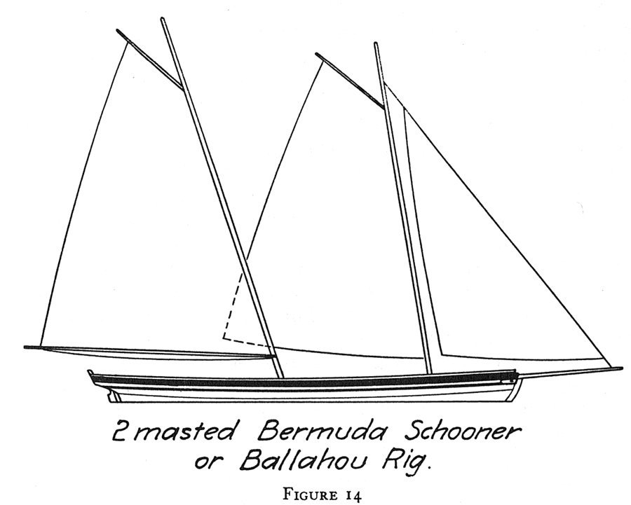
- 22 replies
-
- 2
-
-
- caldercraft
- jotika
- (and 4 more)
-
I was a Nuclear Weapons Officer in the Navy and had a Marine detachment to guard my spaces. I am pretty certain some of the Marines would take exception to CPO cid's comments about marine attire. The dresses they wore definitely were not sexy!
-
Error code 200
Dr PR replied to Blue Ensign's topic in Using the MSW forum - **NO MODELING CONTENT IN THIS SUB-FORUM**
I have seen similar problems with photos in other programs over the years. In some cases it was the problem of the software that generated the photo (camera, phone, etc.). There are a lot of inexperienced programmers out there who are producing flaky software! In some cases the header information in the file was incorrect or didn't match the file type. For example, if a PNG file is renamed or saved as a JPG file, some programs will open it anyway and some won't. The solution is to open the file in a reliable photo editor (Microsoft MS Paint works fine, and it is supplied with every copy of Windows, or was up thorough Win 10). Just open the file and save it as a JPG file. This will write over an original bad JPG file and save it with the correct header info. C:\Windows\System32\mspaint.exe -
Kieth, Beautiful work! I had a similar problem trying to figure out all the antennas and such on the spars on my Okie City model. I searched through Navy electronics manuals and found photos and dimensions for most of them. In your case, since it is a more modern vessel, you might try looking around on marine equipment suppliers' web sites. You can probably find equipment that looks like the things in your photos, and they usually have manuals telling the overall size and mounting footprint.
-
I have this book and it is a good way to "fall down the rabbit hole" just wandering through the illustrations. However, I find it is rarely useful for details of what I am researching. Often there are many versions of a particular type of equipment, and the versions illustrated just aren't right for my particular project. Still, it is an interesting starting point for understanding nautical mechanisms and terminology.
- 4 replies
-
- 3
-
-
- Review
- Book Review
- (and 2 more)
-
Working out the correct height of the masts from the Deck
Dr PR replied to DaveBaxt's topic in Masting, rigging and sails
Dave, You certainly aren't the only one to have had problems deciphering the meaning of "mast length." The problem I have found is that different authors use different definitions for "mast length" and never bother to explain what they are talking about. For example, James Lees "The Masting and Rigging of English Ships of War" never says what he means by mast length (at least I have been unable to find it after reading the book several times). We are just supposed to read his mind and know what he means. I'm not picking on Lees. Almost every other author I have read makes the same error - we are supposed to know what they mean. Harold Underhill is the only author I have found who says unambiguously what he means by "mast length." However, I have been able to figure out what most authors mean, and there are three different definitions of mast length that are used. I have attached a drawing illustrating the various ship dimension terms and measurements. The most common definitions of "mast length" are: Measured length - from the bottom of the mast heel (foot) to the highest point (top of mast head). I think this is what Lees means in his book. Underhill also uses this in most cases. Hounded length - this is the most commonly used definition. It is from the heel (foot) to the hounds. This is the length used in many of the period tables of dimensions. However the meaning of "hounds" is almost never given, leaving that to your imagination. The term "hounds" has numerous meanings among authors, usually the part of the mast the trestletrees of the top rest on. But some authors also include the part of the mast below the top where the cheeks attach, and one even says the hounds extend down 1/3 of the "mast length" (whatever that is). Usually the writer doesn't say if the "hounded length" extends to the bottom or the top of the hounds. Again, Underhill is the only author I have found that explicitly defines the term "hounds" (the point at the top of the cheeks that the trestletrees rest on). I have also found authors who used the "deck to top" and "deck to hounds" measurements for "mast length" but these are not too common. Mast length is often calculated from other undefined terms. "Breadth" or "molded breadth" is most common, and I think the meaning is clear (the "beam" in modern terms, or the widest dimension of the hull). However some formulas base the dimension on hull length, and, of course, they rarely say what they mean. For more modern ships it is the "length between perpendiculars" (distance along the normal load waterline between the foremost point on the hull - fore peak - and the aft most point on the hull -aft peak - which is the center of the rudder post on wooden ships). Some older authors use "length on deck" ((length of the longest continuous deck inside bulwarks) Many formulas use the "line of flotation" (length at waterline between rabbets - grooves in the stem (bow) post and stern post that hull planking fits into). Hope this helps more than it confuses.
-
Looks good! I like the way you made the "thimble" loop.
- 44 replies
-
- 1
-
-
- first build
- Artesian Latina
- (and 1 more)
-
It is interesting that the binnacle was tied down with turnbuckles. This is a carryover from sailing ship days when the compass/binnacle was "portable" and normally tied down to eye bolts in the deck with lanyards.
-
SA-6 Gainful by Baker - FINISHED - Trumpeter - 1/72 - PLASTIC
Dr PR replied to Baker's topic in Non-ship/categorised builds
After they fire the missiles the rear end of that thing is going to need a new paint job! -
And there is the problem that the measuring devices used to design the vessels probably weren't exactly the same as the tools used to build them. Look at the yard sticks and measuring tapes used in modern construction and you can see significant differences in length. If you have ever taken measurements in modern house construction you know that actual construction is far from precise! I have five "accurate" rulers sold for drafting and engineering measurements from reputable companies like K&E, Staedtler-Mars, etc., and when I carefully line them up I can see as much as +/- 0.002 inch difference over a length of 12 inches. I'm willing to bet the rulers used in different shipyards a few centuries ago were not calibrated to very exacting standards! Plus, often there were no real plans. It was all in the head of the ship builder and whatever came out of the ways is what you got. No two ships of the same type would be the same dimensions. So don't sweat the small stuff. Good enough is good enough!
-
I am a lot like Roger. The guns we had in the Navy were 3", 5", 6" 8", etc. When I hear "155 mm" I instinctively have no idea how big that is. I have to stop and divide by 25 (25.4) or 150/25 = 6 to figure that it is a 6" gun. However, even though I am 76 and grew up in the US I really am not sure how many ounces there are in a pound or gallon! I guess I must have gotten some bad scores on tests in grade school. I think the people who came up with noggins, inches, furlongs, ounces (and Troy ounces),fathoms, pottles, bushels, firkens, kinderkins, pints, gallons, yards, chains, pecks, miles (and nautical miles) ... and all the other ridiculous Imperial measurements were a few cans short of a six pack! None of it makes any sense. No one in his right mind would come up with such a mess, and were are all stuck with it! All of the scientific work I have done was in metric, and that makes perfect sense to me! But it was in electronics design that some sense was worked into the Imperial system. We did everything in decimal fractions of an inch. Not true metric, but much better. To this day I think in 0.25", 0.125", 0.0625", and such units instead of 1/4, 1/8 or 1/16 inch. But even there some weirdness crept in. Transistors and integrated circuits originated in the US along with their packaging. Everything in decimal Imperial units. But when we started using parts from Japan and Europe I really had to scratch my head The units were metric, but the values made no sense. Why would anyone design a new part with a dimension of 1.27 mm? Or 5.08 mm?? Or 1.5875 mm?? Then I realized that the parts were being produced overseas in Imperial units (1.27 mm = 0.05" or 50 thousandths, 5.08 mm = 0.2 inch, 1.5875 mm = 0.0625 inch or 1/16 inch) but the data sheets used metric dimensions. That was really strange! But I got used to it and found it was easy to make part of a design in Imperial units and another part in metric. Whatever. I could have used cubits if necessary. The actual units just don't matter. Things are as big as they are no matter what units you choose to measure in. **** But in ship modelling I have a word of advice. Use the measurement system the original ship was designed in. This will avoid a lot of measurement conversions, and that invites errors. Also, sometimes the actual dimensions of a part are unknown, but you can make a close guess. It is far more probable that an old English or American shipwright worked in common fractions of the Imperial inch than in millimeters! Likewise, you wouldn't expect a French or Dutch shipbuilder to use Imperial units. To carry this idea a step further, I do all my design work in CAD. Over a period of 14 years I created a very detailed CAD model of the exterior of a 610 foot guided missile cruiser, including every part 3/32" (0.09375 inch or 2.38 mm) or larger. Approximately 1/3 of the approximately 1 million parts are rivets, screws, bolts, nuts and washers. Almost everything was based on the original builder's blueprints and drawings in technical manuals. I designed the model 1:1 scale - no problem in a computer where the virtual universe is practically infinite in size. This allowed me to proceed without wasting time converting measurements to a smaller scale. That reduced the chance for error. Of course, not all dimensions were in the paperwork, and I was only able to get a few critical dimensions by visiting the last remaining ship in a museum. But when I had to make "guesstimations" from photographs and sketches, I was confident that the mid 20th century US designers did everything in fractions of an inch or foot - 1/16, 1/8/,1/4 and 1/2. Every dimension in the blueprints and manuals used these measurements. In most cases guesses based upon the closest fraction fit seamlessly into the known dimensions. When I get around to finishing the 1:96 scale model I will just change the scale of the entire drawing to 1:96 and take my model measurements directly from the scaled CAD model. No time wasted with unit conversions and scale calculations.
-
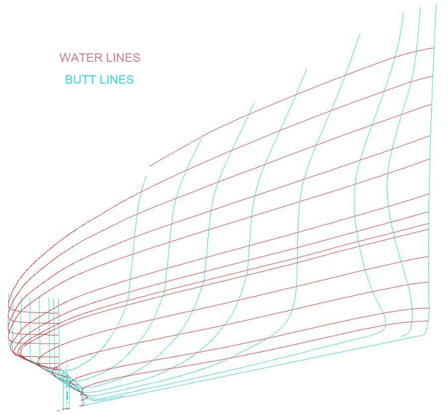
DesignCAD 3D MAX can easily generate unlimited cross sections of a hull in the X, Y or Z planes (section lines, water lines and butt lines). The "Contour Line" function (Draw/Lines/Contour Line) will generate cross sections lines in any plane at any position. You set a point on the plane and tell the Contour Line function to generate an intersection line with the hull and an imaginary plane that passes through the point in the X, Y or Z plane. The transverse contour line through a hull is the shape of the frame. Basically it is the same thing as drawing a plane that intersects the hull and using the "Draw/Lines/Surface Intersection" tool, but without having to create the intersecting plane. I just create a series of points at the desired spacing along the length of the hull, create a contour line at one of them, then move the cursor to the next point and use the "F3" "Repeat" function key to repeat the Contour Line function, and so on down the line of points. But if it is something you do often you can write a BasicCAD macro program to determine the length of the hull, divide this into some number of equal spaces, and generate the contour lines for each section automatically. Contour lines are also extremely useful for fairing the curves of a hull. I create waterlines (horizontal plane intersections) at various elevations and then look at them length wise. If there is any slight kink in what should be a smooth hull surface it is readily evident, and easy to locate the point on the hull that needs fixing. For modern hulls where you have a Table of Offsets it is fairly easy to generate a CSV (comma separated variable) text file from the offset data and feed it into the program to automatically generate all of the curves. However, the engineers or draftsmen often made "typos" when they were entering thousands of numbers from calculations into the tables. These are usually single unit errors (1/8ths, inch or foot) that cause very noticeable bumps and dips in contour line waterlines generated on the hulls, and then corrections are easy. Here is an example of water lines and butt lines generated with the DesignCAD Contour Lines function for a Cleveland class cruiser hull: