HOLIDAY DONATION DRIVE - SUPPORT MSW - DO YOUR PART TO KEEP THIS GREAT FORUM GOING! (Only 72 donations so far out of 49,000 members - Can we at least get 100? C'mon guys!)
×


BANYAN
-
Posts
5,946 -
Joined
-
Last visited
Content Type
Profiles
Forums
Gallery
Events
Everything posted by BANYAN
-
 Folks I post this with a little hesitation - mods please delete if it exceeds guidelines. I came across the following airbrush deal the other day which is real value-for-money BUT it appears to be a Chinese knock-off even if sold in USA. As such I cannot vouch on how much of a knock-off it is? That said, and if OK to post; the package offers everything you need except the air-compressor. As discussed in the YouTube review, the cost of the accessories included is greater than for the whole package. His tests als0 show that it works well. For consideration and apologies if this product is overstepping the 'piracy code'. Amazon.com: NEOECO Multi-Purpose Airbrush Kit, Dual-Action Gravity Feed Air Brush Sets with with Crown Nozzle, 9cc 20cc 40cc Cup, 0.2, 0.3 & 0.5mm Needles for Makeup Nail Art Shoes Tattoo Cake Toy Model : Arts, Crafts & Sewing Here is the review I base this on. Sorry - I had the wrong link here (30 Jan 2022) cheers Pat
 -
An interesting mix of modern and traditional modelling techniques Mike. Interesting subject also. cheers Pat
- 10 replies
-
- 3
-

-
- finished
- Horizon-class
- (and 1 more)
-
Thanks, interesting vessel - it's a pity we are slowly losing all of these maritime assets. cheers Pat
-
Yep, there would definitely been only a pair of 'train' tackles Dave, the front hooks will have probably been moused on and the after hooks moved to the best ring for maximum 'advantage'. I know you don't intend to add masts etc, but it would have been interesting to see the dangling tackle used for loading the mortar shells . cheers Pat
-
Hi Spyglass; which ship is this? cheers Pat
-
Looking good Keith; as others have said, your explanation for this process is very clear and well demonstrated. I continue to enjoy your updates. cheers Pat
-
Wow Dave, some significant progress; looks great. Have you sorted out the rigging yet? cheers Pat
-
Looking good mate. cheers Pat
-
Nicely done Bob; glad to see you persevere through your initial tribulations. They look great! cheers Pat
- 179 replies
-
- 3
-
-

-
- Second Build
- Pinta
- (and 2 more)
-
Iron Mast Cap Orientations in Steam/Sailing Ships
BANYAN replied to BANYAN's topic in Masting, rigging and sails
Thanks Eberhard, that is much appreciated - and just as I was settling on parallel . Seems perpendicular is correct (for European ships at least). Based on the imagery I think the slightly inclined (not entirely parallel) would fit with your assessment. cheers Pat -
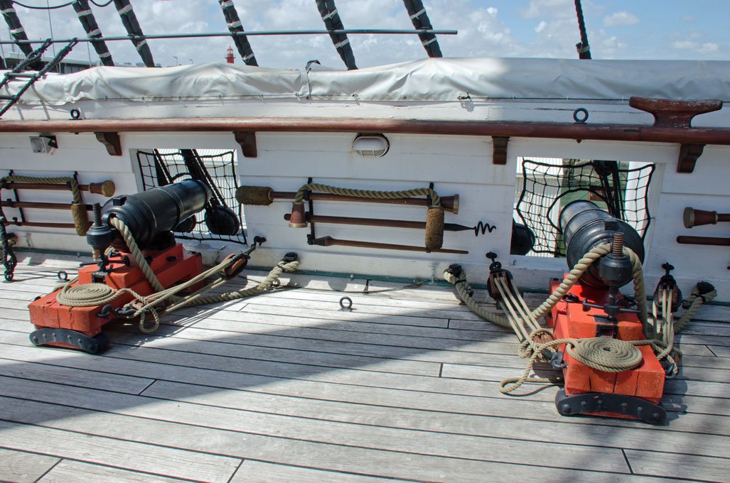
A lot of British and European ships in the 19th century had much of the larger bits and bobs such as rammers, sponges, worms, ladles etc stowed in racks attached to the bulwarks; not sure what was done earlier. However, I have seen some images of these stowed in the overhead for the lower gundecks. Powder cases, slow fuse, lanyards etc were collected from the magazine by the designated number (sometimes a powder monkey' while the gun was being readied by the rest of the crew. Ready use shot was usually stowed in 'shot garlands' around hatches etc, or on the bulwark. When action was likely (and the weather permitted), sometimes guns were readied well before action, which then just required them to be 'primed'. I cannot comment on the practises used in 'Constitution' as I am not familiar with US vessels. cheers Pat
-
Iron Mast Cap Orientations in Steam/Sailing Ships
BANYAN replied to BANYAN's topic in Masting, rigging and sails
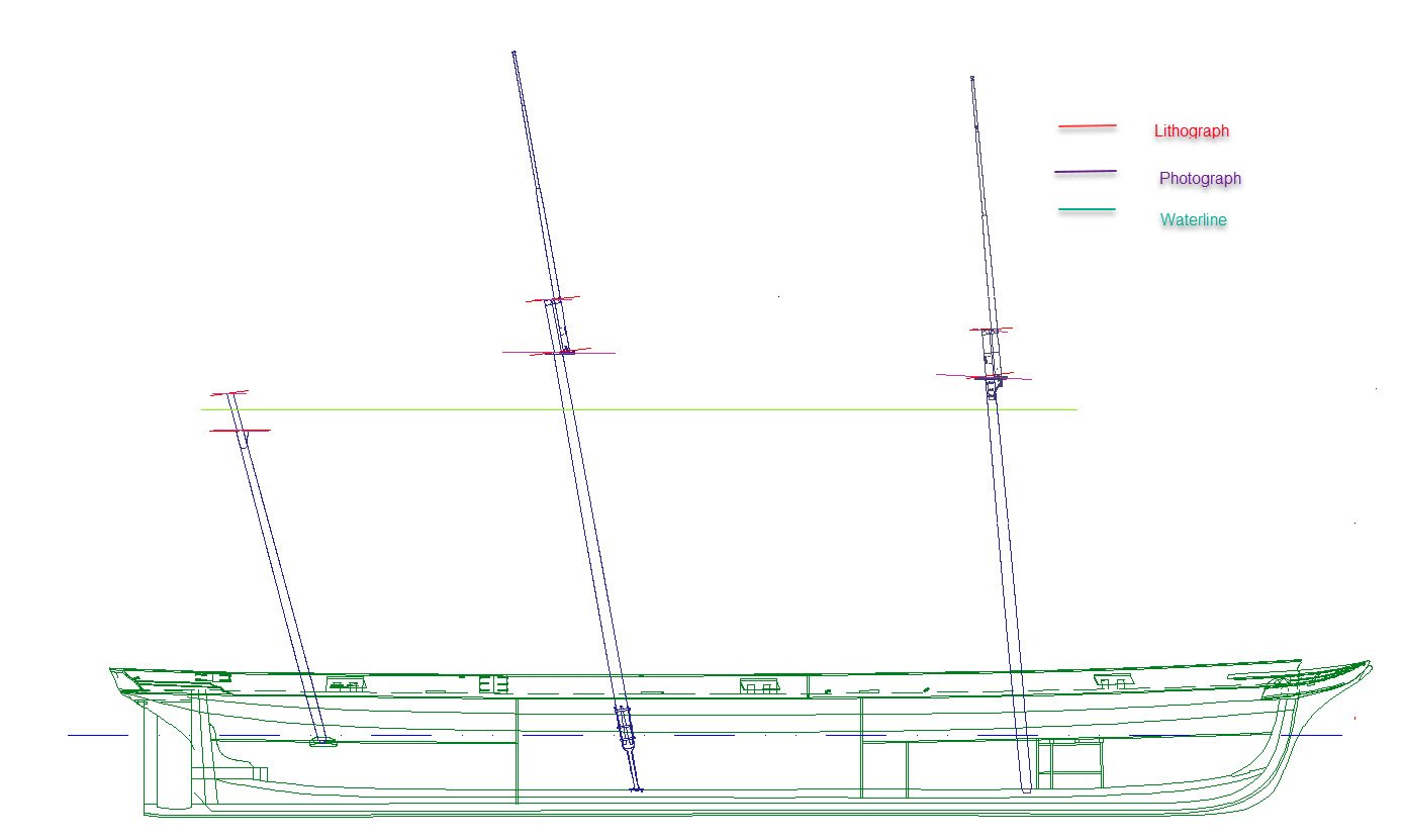
Thanks again for the additional contributions; this will be a valuable resource for others also, I hope. Mark; the rigging of the ship in this instance was set-up in accordance with the new Captain's wishes. Initially, the masting and rigging was to be to RN standard, as the build superintendent was an RN Commander. However, when he decided not to return to Australia, he passed the masting and rigging supervision to Commander Norman (ex-merchant captain) who brought her out and commanded until 1867. I have found a bit of correspondence on this matter which helps a bit, but apart from mentioning some sails does not go into detail other than to state the rigging was altered in parts (mainly the yards) to 'merchant ship standards'. The ship sailed with, and going by the imagery retained, the rakes of the mast as 5 degrees (foremast), 10 degrees (main) and 15 degrees (mizen). John, thanks for the images which appear to support parallel to waterline. The following illustration (Main Mast-Head of a Steam Vessel) is from Kipping, Rudimentary Treatise on Masting and, Mast-making and Rigging', 1854, p15. This shows the masthead was indeed squared for a cap. The following is a quick alignment exercise I did to try to determine the alignments of the caps and tops using the lithograph (as built) and a photograph (1865). I don't think anything concrete can be determined as the distortions introduced accounting for the aspect (point of view) used by the artist/photographer shows the lines all over the place. perhaps, if a little allowance is made for this, the best interpretation is that they were paralleling the waterline (well the tops at least). Ignore the hounds I have drawn, as they were done before this exercise. Essentially, I embedded the images, scaled them to the correct waterline to match the profile (taken from the sheer drawing) and put on lines aligning with each mast fitting. Again, many thanks for all the feedback and suggestions; much appreciated. Pat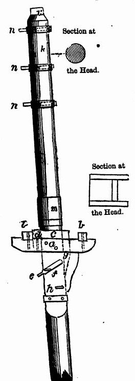
-
Iron Mast Cap Orientations in Steam/Sailing Ships
BANYAN replied to BANYAN's topic in Masting, rigging and sails
Hi all, and again thanks for the feedback and comments. Keith, as Rob has said, from the mid-19th century on, most sources/evidence seems to suggests the caps were parallel to the waterline with perhaps some exceptions. The side view drawing provided shows how the cap will have been fitted to achieve a parallel fit. This arrangement would have allowed the cap to be first fitted to the lower mast head squared tenon, in the same way as wooden caps were fitted (which used an angled tenon to prevent the cap drooping forward). As the square hole in the cap was the same shape but, set on an angle, it will easily have accepted the tenon - the base of the tenon (stop cut) will have been angled to match/offset the rake and let the cap sit square. Essentially, we are just putting the angle on the mortice rather than the tenon. If you project a triangular piece of the tenon protruding on the forward upper end of the squared hole in my first post left hand image, it might help with this description? Once snugged down, the cap will have sat parallel to the waterline, then the topmast raised through the round hole to the front which was angled to the rake of the mast so that it would have gone through quite easily and remained parallel to the rake for that mast. Rob, agree, not sure if I said press fit though? As far as I know they were iron and had sufficient clearance in the holes to allow for leathering and the mast to fit with a little play for the topmast - as you say, the rigging kept the masts rigid. However, I think the squared after hole to fit on the lower masthead tenon, will have been a snug fit to keep the cap in alignment fore-and-aft. One of the authors (I think Lees) points out that the cap hole was squared to keep the cap squared to the masthead. Eberhard, as to cast or forged iron, not sure which; the contract simply called for iron. Agree on the equal and parallel wall thickness (where possible) - I have allowed 1.5" iron all round, and room for leathering and .25" play for the topmast as suggested by the authors (Fincham in particular). I should have provided the top view of the cap which shows that. I am basing the shape of the top on that depicted in the lithograph which shows a rectangular shape (side on) rather than a parallelogram, which means there will have been more 'meat' in the fore and aft ends to accommodate the slope (=weight as you suggest). A sloped ends cap would/should have been depicted otherwise? An alternate is that the cap, as built, was wooden, and changed to iron during the mast/top replacement in 1860/61. I am very open to alternate designs in iron. The model I depict is right on the cusp, but probably with the older masts when deployed to the Wars in NZ (1860). I think am going to have to ponder on this a little more. Much too much guesswork here without some clear primary evidence or guidelines from the time. One thing I will redo is look at the embedded images as underlays in my CAD drawing and see what angles are actually depicted rather than what they seem to be doing. I am still not convinced either way. If I go by 'as built' they will have been squared and (based on the lithograph) possibly set perpendicular - but the imagery is confusing. If I go by the photograph, the cap is more likely to be parallel to the waterline and be an iron cap with equal thickness iron walls all round. cheers Pat -
Iron Mast Cap Orientations in Steam/Sailing Ships
BANYAN replied to BANYAN's topic in Masting, rigging and sails
Thanks all for the valued comments. Keith B. WRT to fitting/making caps that are parallel to the waterline, checkout the pdf drawing at post 3. These were cast iron so creating something with the correct internal angles (for rake - see dashed lines in the drawing) is not difficult at that time, and such a fitting will have held the masts snuggly and without offering injury to them. I agree, sailors will not have had any real issue working tops at any angle, but in earlier days the angle may have been a consideration for the marine sharpshooters posted in the tops? Rob, thanks, I did not post a full picture showing the waterline as that only leads to more confusion based on the angle/aspect the artist/photographer used. Generally, with one exception the angles are close enough (allowing for some distortions) to suggest that the caps were set parallel to the waterline. I agree, aesthetics was also important, and I think, based on the correspondence I have from the designer to the build superintendent, that aesthetics was a design consideration. Roger, that indeed was an eye-opening movie; he must have had an extraordinary sense of balance akin to trapeze/high wire artists. Overall, the weight of evidence I have found, or been pointed to, indicates that prior to the mid-19th century, there is a mix of perpendicular to the mast and parallel to the waterline for the caps, but it appears that generally the tops were parallel to the waterline. After the mid-19th century though, it appears that generally the caps and tops were both parallel to the waterline - BUT, as with all of these 'rules' some exceptions to the rule must be entertained. Therefore, perhaps the best guidance I can follow is that offered by the imagery of Victoria, and while there is some contradiction between the lithograph and the photograph, the best interpretation I can make is that they were all parallel to the waterline. I remain open to further comment and suggestion and would dearly like to find some irrefutable primary evidence to confirm either way. cheers, and thanks all. Pat -
Sorry Jason, I have not checked in the kit builds for a while and missed your updates. She is looking superb; lovely work indeed. cheers Pat
-
Iron Mast Cap Orientations in Steam/Sailing Ships
BANYAN replied to BANYAN's topic in Masting, rigging and sails
As stated above, here is a summary of what I have found so far. I still find it very strange that the contemporary authors did not cover this subject in any greater detail; especially in the books on Naval Architecture. I would greatly appreciate further comment based on the attached pdf. As the model is depicted circa 1861, it is right on the cusp of when the masts were replaced (as shown in the photograph - see pdf) so it could have followed either syle of heavy or light mast caps as depicted on build or in the photograph. Many thanks for your interest and suggestions. cheers Pat Cap and Top Alignment Issues.pdf -
No holding you back is there; significant progress already. Looks good Glen. cheers Pat
-
Iron Mast Cap Orientations in Steam/Sailing Ships
BANYAN replied to BANYAN's topic in Masting, rigging and sails
Thanks Rob, appreciate your input. I have been trawling through the NMM, Danish Digital Museum etc at plans/drawings for contemporary vessels to try and get a handle on this. I have also been scanning through Nares, Kipping, Fincham and other authors who do not give very much info on the alignment of the caps, and very little on the alignment of the tops. Lees bases his on the models and drawings of his period of interest so nothing conclusive. The best they have to offer on the tops is that they were placed horizontally - but horizontal to what? Perpendicular to the mast or parallel to the waterline? I will post a summary of my findings later this week showing what I have found, and if anyone could contribute to that it would greatly appreciated. I accept that aesthetics is also a contributing factor, but I also have to allow for working practicality, strength of the fitting, and of the attached fittings (such as the lead and strength of the roller abaft the cap), etc as you have suggested. Thanks again for your feedback/suggestions which are always gratefully accepted - sorry I missed your earlier response ( I'll blame the lethargy inmduced from the New Year celebrations . cheers Pat -
Thoughts are with you and the family Vladimir; hope all turns out well for you all. regards Pat
-
Iron Mast Cap Orientations in Steam/Sailing Ships
BANYAN replied to BANYAN's topic in Masting, rigging and sails
Thanks Michael. I have been doing that over the past few days and also trawling through the various authors (especially naval architects). It is unusual that most are shy on discussing this. To date, I have established that only a few make the statement that the tops were set "horizontally" but do not specify whether horizontal to deck, waterline or to xxxx. None mention the cap orientation at all. I am putting something together which summarises all this research which I hope to post in a day or two. In the meantime, I will keep looking. cheers, and appreciate the feedback. Pat -
I think you may be 'fibbing' just a bit Glen. To come up with this idea, and then blame your mate and son, suggests you may have drained that bottle yourself . Anyways, it is another very clever and interesting way to display your miniature masterpiece 🦑. Now where is that bottle of 'sauce' - I need some inspiration. I'm also along for the ride; look forward to you log. cheers Pat
-
Iron Mast Cap Orientations in Steam/Sailing Ships
BANYAN replied to BANYAN's topic in Masting, rigging and sails
Thanks Mark, actually, the attached might shed better light on the internal arrangement which shows the holes for accepting the spars angled to the appropriate rake? This is for the Mizen which has the greatest rake and as you can see, the mast would still get full support. These would have been cast parts so the complexity would not have been an issue, I think. But I would tend to agree that most are shown at 90 degrees/perpendicular to the mast axis - it just sort of looks wrong on such highly raked spars. My real issue with the left (drawing version) is how they will have press-fitted the iron cap on at such an angle - which sort of drives me to the perpendicular anyway. cheers Pat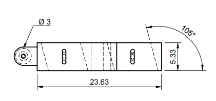
-
Iron Mast Cap Orientations in Steam/Sailing Ships
BANYAN replied to BANYAN's topic in Masting, rigging and sails
Thanks Keith, so it is one vote to the perpendicular to the mast (option 2 above). cheers Pat -
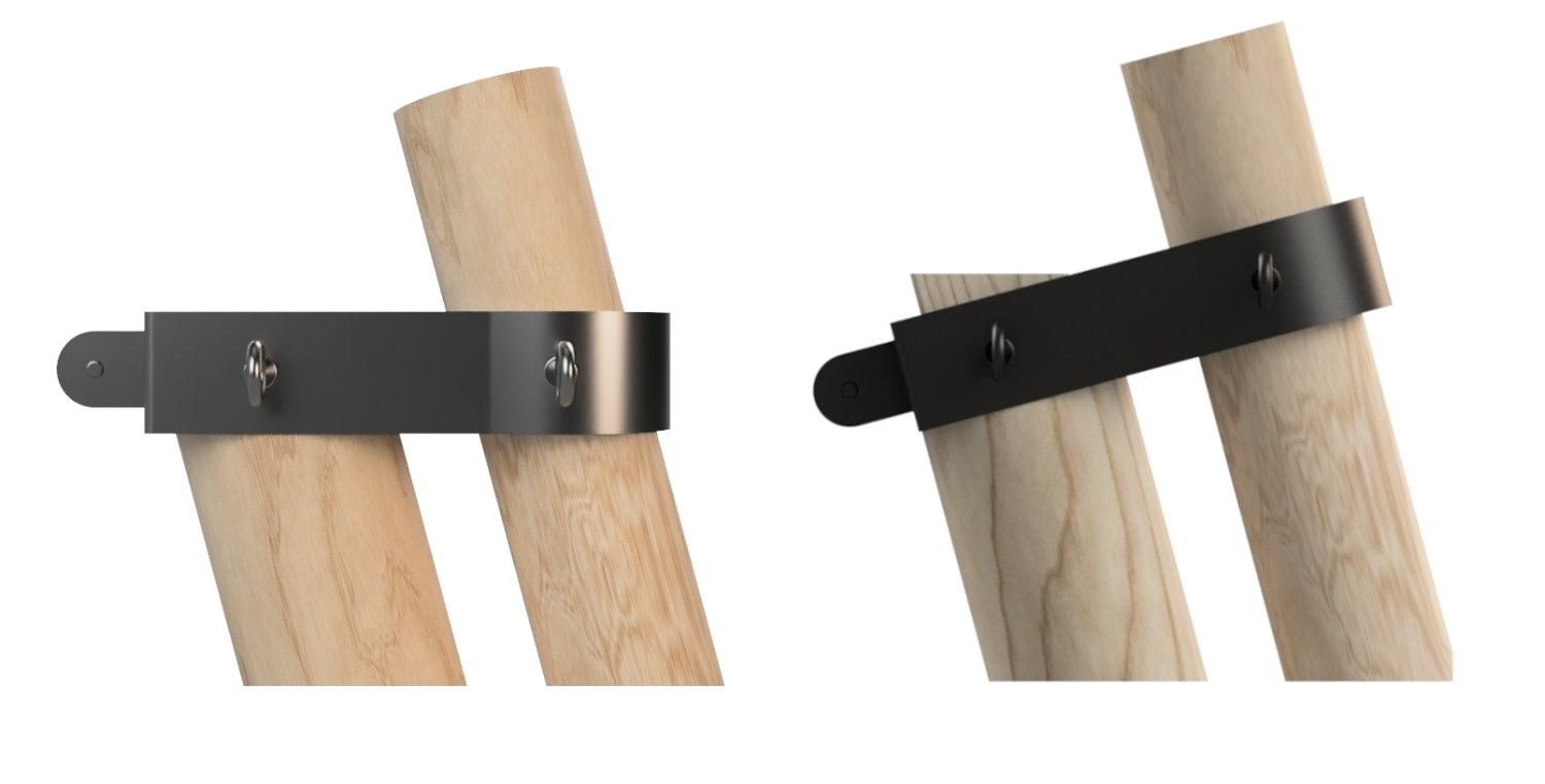
Hi folks, I am trying to determine the orientation of the iron mast caps in steam/sail screw vessels (mid-19th century). I have established the form/construction of these from contemporary authors, but they are shy in stating whether the cap was placed horizontal (parallel with the tops to the waterline) or perpendicular to the masts? The imagery does not clearly show one or other in the two lithographs and single photo of the ship, as in some instances they look parallel and in other perpendicular. Either form is easily made as the fittings will have been cast. Even with the severe rake of 'Victoria's' masts (5/10/15 degrees for the fore, main and mizen respectively), the angular displacement within the cap could have been cast once the dimensions were determined. The following show the two options (images used with permission) and I seem to recall one author saying perpendicular, but it does just not look right? The protruding lugs at the rear hold a roller for the topmast forestay next abaft. If horizontal is correct, its position has to be lowered a little as the imagery shows a couple of inches of the squared mast head protruding. I would greatly appreciate the 'correct steer' on this, preferably with some evidence so that I can cite it), but any suggestions are most welcome. cheers Pat