BANYAN
-
Posts
5,957 -
Joined
-
Last visited
Content Type
Profiles
Forums
Gallery
Events
Everything posted by BANYAN
-
Many thanks Kevin, much appreciate these. cheers Pat
-
 That'll make a very exciting activity for the lucky recipient - what a great Christmas gift for your granddaughter - Captain Bean will have lot of fun and many fond memories Love her face in the porthole. cheers Pat
 -
Hi Keith, as expressed by Druxey I also have run out of superlatives for your build. The enjoyment I have gained from following along cannot be adequately described. Thankyou for sharing. Tom, a great photo - you almost have a full crew there . Grandkids are what it is all about at this stage of my life - the enjoyment I get in their company is a wonderful pick-me-up. cheers Pat
-
Hi Vlad, again an interesting update to your build. She is coming along very nicely, and I think you undersell your skills a little. It is great to see your positive attitude to the constructive criticism and suggestions offered; it makes such a refreshing approach compared with many who see such as an attack on their character/abilities. cheers Pat
-
Brian, I have thoroughly enjoyed following your build and I am now a little disappointed that it is finally complete, and I won't have something new to see what you have achieved. What a splendid display of skills in building this, and the effort is well rewarded with the magnificent model you have to show for it. cheers Pat
-
What a terrific achievement Glen, she looks great in her 'glass' home. This has been another fascinating build to follow, and you have set your 'benchmark' very high for the follow-on build cheers Pat
- 134 replies
-
- 4
-

-

-
- Captain Kidd
- bottle
- (and 3 more)
-
Looking good Vladimir, nice, neat work. cheers Pat
-
The assembled vessel looks great Glen, very nicely thought through and executed. cheers Pat
- 134 replies
-
- 6
-
-
-
- Captain Kidd
- bottle
- (and 3 more)
-
When you trailblaze you have to expect such dilemmas Glen; it is how you overcome that matters and you have done a great job. cheers Pat
- 134 replies
-
- 5
-
-
- Captain Kidd
- bottle
- (and 3 more)
-
Nice work Wonko, a lovely example of miniature working engineering. Look forward to seeing more. cheers Pat
-
Working for me also Shipman and Kevin. Many thanks Kevin some great detail photos there that will be useful for my research also. cheers Pat
-
Rob, what a great artifact to have, and very nicely presented after your efforts with the shadow box. cheers Pat
- 3,560 replies
-
- 2
-
-
- clipper
- hull model
- (and 2 more)
-
Love those pumps Vladimir; very nicely done - they look greatg. cheers Pat
-
Love the time and effort you are putting into the oarsmen and their bench seats etc Richard; it will make for very realistic detail on the model. cheers Pat
-
Looks good Glen, she'll be afloat before you know it cheers Pat
- 134 replies
-
- 5
-
-
-
- Captain Kidd
- bottle
- (and 3 more)
-
Nice work mate; looks good. I like the yard trusses; very well made. cheers Pat
-
HMCSS Victoria 1855 by BANYAN - 1:72
BANYAN replied to BANYAN's topic in - Build logs for subjects built 1851 - 1900
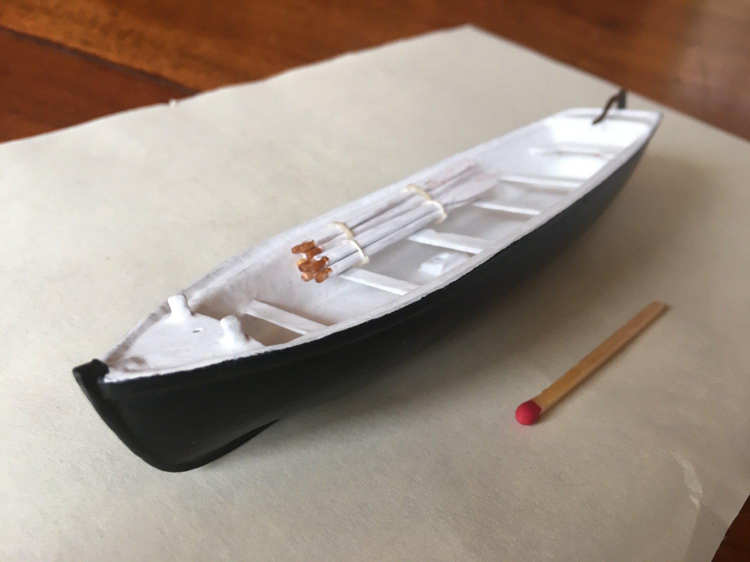
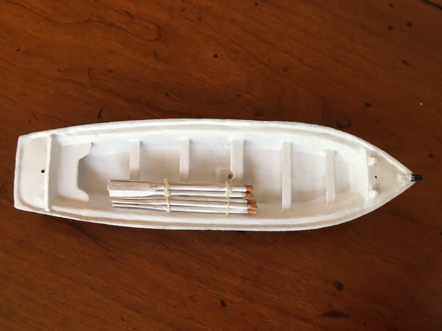
Thanks John. Hi Keith, the whole is made from wood. The hull was carved from a block then hollowed out to shape; then the lining simulating cork covered with canvas) added. I have still to add duckboards, lifting gear etc. We have omitted the tholes at the moment as they are so small art this scale - but I am tempted to do this when I add the pre-painted (vermillion) rubbing strakes and boat badges in the bow. I have yet to come to grips whether hanging loops would have been included with the rubbing strakes, for men to hang onto or assist their scrambling into the boat. The UK Life Saving boats were starting to show them, but not evident in the NMM model. cheers Pat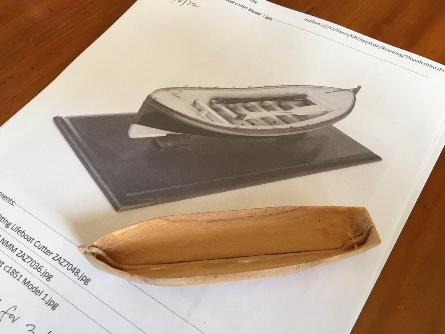
- 1,013 replies
-
- 10
-
-
- gun dispatch vessel
- victoria
- (and 2 more)
-
HMCSS Victoria 1855 by BANYAN - 1:72
BANYAN replied to BANYAN's topic in - Build logs for subjects built 1851 - 1900
While I have been continuing to research the rigging outfit, another member has completed a remake of one of the lifeboat-cutters. The Victoria carried two, one of 27' the other 30' - the remake was to correct the length of the second one as we found that info a little later. I have still to add a vermillion painted rubbing strake, the falls hook on/slinging points and a few details, such as boat badges, masts, ropes, bailers, etc. These boats had cork, covered with canvas, floatation in the bow, stern and along the sides which is why they look so 'full/thick'. cheers Pat

- 1,013 replies
-
- 13
-
-

-
- gun dispatch vessel
- victoria
- (and 2 more)
-
Great news, good to see models being displayed at such important venues. The Bridge mini-diorama looks great. cheers Pat
- 88 replies
-
- 5
-
-
-
- Australia II
- Finished
- (and 2 more)
-
Great to see the update and hear you are on the right track with your little beauty. cheers Pat
-
Great progress and some nice work there mate; looks good. cheers Pat
- 179 replies
-
- 3
-
-
-
- Second Build
- Pinta
- (and 2 more)
-
It still amazes me how those masts retained sufficient strength after having a sheave cut through them; your piccy illustrates just how little 'meat' was left to either side. You're making great progress Vlad, I am enjoying following along. cheers Pat