BANYAN
-
Posts
5,966 -
Joined
-
Last visited
Content Type
Profiles
Forums
Gallery
Events
Everything posted by BANYAN
-
 A very creditable job Hellmuht, especially noting the small amount of glue used. cheers Pat
- 158 replies
-
- 1
-

-
- byblos ship
- Egyptian
- (and 1 more)
-
Still grappling with the research for Victoria Dick, but the 'hint' is noted cheers Pat
-
Look forward to seeing your progress with this build Dick. Having seen Steven's efforts up close I have started taking a real interest in vessels of this period. Steven, I thought I would just help you draw out a good thing cheers Pat
-
A late comer to your build log, hope there's room in the peanut gallery? A very nice looking hull frame Dick; it should make into a great hull when planked. Have you asked Steven to make some crew for you - he's right into the carving mode now (ducking for cover) cheers Pat
-
Just found your log Hellmuht. A very interesting subject for a model and I will continue to follow this intriguing build. You have done a great job on the hull. cheers Pat
- 158 replies
-
- 3
-
-
- byblos ship
- Egyptian
- (and 1 more)
-
Converting a Backyard Shed into a Model Workshop
BANYAN replied to Hank's topic in Modeling tools and Workshop Equipment
All is starting to look shipshape again Hank; nice job. Don't fall into the same trap as me, I packed/sorted things so well I have to try and remember where I put them; usually results in a 'deep dive' To get easier access I now have a pegboard again for the most often used tools. cheers Pat -
Thanks again Mark, your thoughts and suggestions. Based on your thoughts re interpretation of the wording - this makes much more sense now in reading this as an iron knee fitted in the 'head of the vessel' rather than the Knee of the Head as you point out. ED Tosti's shows Young America also had a similar arrangement, so based on this I am now beginning to think that an iron knee replaced or supplemented the breast hook; I am leaning to supplement. This interpretation (as a supplement) provides a strong bow and a fixing point for the shrouds etc. The positioning of the knee could be such that it would reinforce the Bulwarks, align with the cheeks (as you also pointed out) and provide more spread for the Bowsprit shrouds (but still not very wide considering the sharp bow arrangement) Thanks again for your insights, much appreciated Pat
-
Hi Mark, many thanks for your response. you are asking all the questions going through my head also WRT to it being an error in the Contract, or more specifically the Specification, I cannot be certain. The Articles of Agreement (Contract) was all the legal stuff and I have a true copy of that (which I have transcribed). The Articles had the Specification and the first Rigging Warrant as attachments. The only copies of the Specification I have found are the 'officially' transcribed copies (for Gazetting in Government Records). Whether the author of the Specification (Oliver Lang, Mast Shipwright at Pembroke 1855) made the error (if it is one) which is unlikely, or whether an error was made in the official transcription (which is also unlikely but possible) cannot be determined - I am assuming this was correct as much of the document is very true to other correspondence and imagery I have - some changes were made like a change in the steering wheel from double to single were made - but I have not seen obvious errors. WRT Cathead, I also had this thought. the Jib and Jib boom guys (wire rope) were led via whisker booms on the Catheads, so having the bowsprit guys go somewhere nearby makes sense. This also ties in much closer to the guidance provided by Kipping and Fincham in the 1855 editions of their respective 'Papers/Books'. Their guidance suggests they should go to a point just above but abaft the hawse pipes to be clear of the ground tackle. All that said, looking at the imagery (photograph c1868) and 2 lithographs (as launched - one showing her going to port, the other to stbd which between them expose/show 99% of the rigging) show the Bowsprit shrouds (guys) going to a point on the headknee just under the bobstay plate - unfortunately no detail is discernible. As the ship had a black hull, it may be the artist could not show it (although they show some other stuff) One other thought I have had, is that in reading the description/requirement literally "Iron knees on both sides of head knee for bowsprit shrouds, ..." - it does not say for setting-up the sshrouds - may simply have been booms/whiskers similar to whisker booms on the Cathead? I guess I will just have to 'suck it up' and make a decision soon - at this stage I will keep researching in the hope of finding something a little more definitive. cheers Pat
-
Bump - anyone? My real issues here is that I have never seen a vessel with protruding iron knees in the knee head of the bow. cheers Pat
-
Wow - what else can one say but Wow! Your attention to and execution of such fine detail at this scale is extraordinary Eberhard. cheers Pat
-
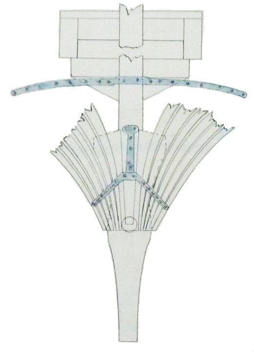
Hi folks. Another question for the more experienced in rigging and construction. The Contract for HMCSS Victoria (1855) stated a requirement for "Iron knees on both sides of head knee for bowsprit shrouds, ..." This has me a little confused as contemporary authors such as Kipping and Fincham (1855 editions), and knowledgeable authors such as Underhill, describe the set-up of these shrouds/guys to a point slightly abaft and above the hawse holes. The Contract has proven mostly accurate but did result in some deviations during the construction of the ship. This creates several questions in my mind for which I would value feedback: Would the set up on the knee of the head (head timbers) have been implemented?. Victoria had a narrow (Aberdeen style) bow which would not have provided much spread for the (bowsprit) guys. The Jib and Jibboom guys/shrouds were rove via whisker booms on the cathead then aft and set-up to rigging screws just forward of the Fore Channel (confirmed by imagery). I am assuming to eye bolts or eye plates? What type of knee would have been used? There is evidence from Master Shipwright Oliver Lang (ship designer) showing 'Buck's Knees' as part of a survey of British Naval Dockyard practices (mid 19th century) in an effort to standardise the fittings used, and how they were fitted. The lower knee (crutch) also incorporated support for the bobstay plates. I am assuming these replaced the breast hook (upper) and perhaps the timber knees (lower) What alternative fixings may have been used? Would an eye bolt, perhaps picking up one of the bolt/rivet holes in the iron knee/crutch (as shown below) have been an option? Any feedback, suggestions or corrections most appreciated as usual. cheers Pat
-
Looking forward to the further updates cheers Pat
-
Nice fix Steven, you would have regretted not doing them. In the vein of Druxey's comments - a thight for thore eyes! cheers Pat
-
Converting a Backyard Shed into a Model Workshop
BANYAN replied to Hank's topic in Modeling tools and Workshop Equipment
Aw come on Hank that's the sickbay isn't it? Far too clean, that deck needs some scuffing cheers Pat -
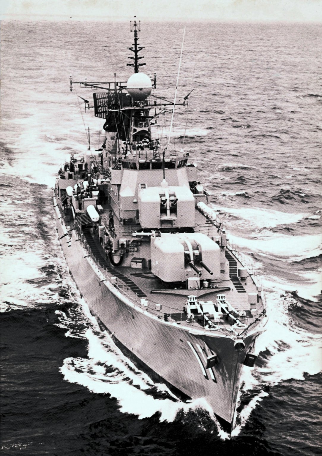
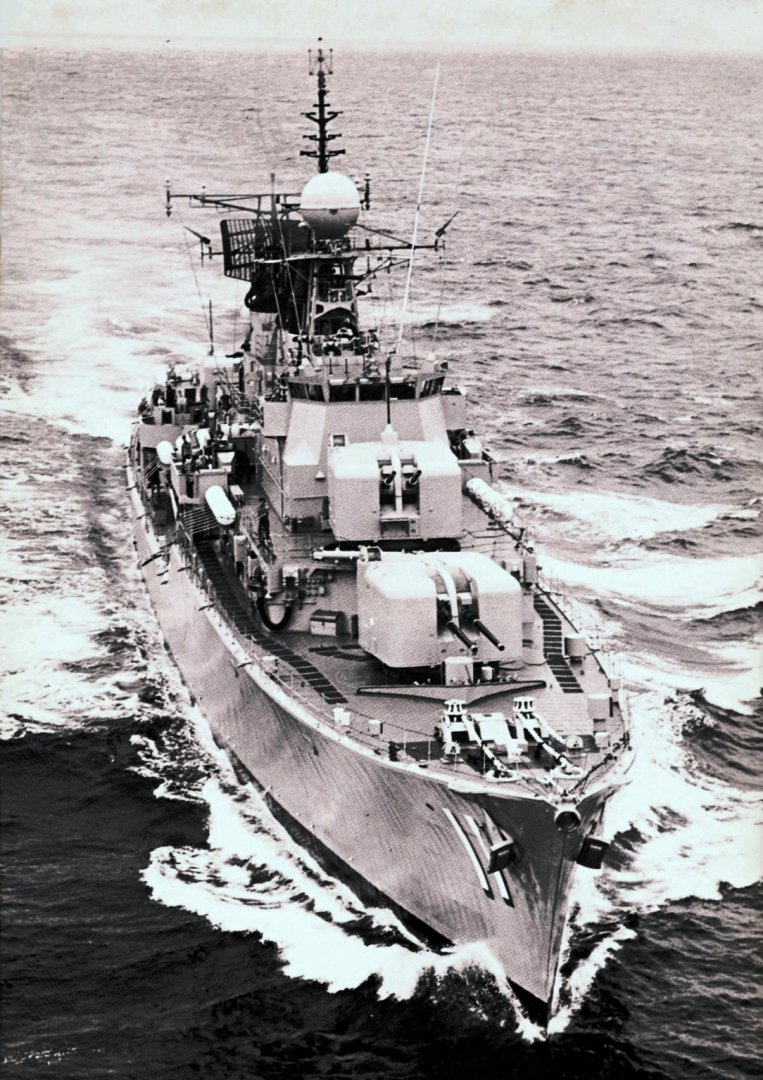
While this method was used by RAN (and RN I think) ships, it may useful to know that even up to the very early 1970s, the RAN used strips of heavy duty sandpaper as deck tread until the introduction of two part epoxy based granular paint (some sort of sand or grit introduced to the mixture). The sandpaper strips were reasonably large strips self-adhesive (sticky backed), and kept pretty by using a very thin (much diluted) flat black paint. I do not know if the USN employed similar methods. This older B+W photo of HMAS Vampire shows what I mean. As you may also note, the forecastle was given a checker-plate and welded strip treatment to assist footing grip. I hope this helps. cheers Pat
-
Keith, I think there would have had to be a slide on the door side of the strut - as the door went up and down it would slide to maintain the right angle. In the raised position it is correctly positioned, but as you lower the hatch door the door end of the strut, probably on a hinged sliding plate in a track, would move closer to the upper side of the door? I am not a engineer so may be shot down in flames on this suggestion All guns to bear - fire when ready! cheers Pat
-
Mark, that's a messy solution, especially on a phone! More so, that when I click on a period button I am immediately taken to that subforum so would need to go back to open the window anyway? Have I missed something? My way of reading/perusing the logs is to quickly see what logs are new and may be of interest to me. When the listing was a single page it was simple to just open one listing list and scroll through - only one action (except for a page turn/ next page if required). While the period groupings may make it easier to find something, there are now additional steps to be taken between opening and viewing each period. On paper this may seem/read as a minor issue (extra steps) but when trying to quickly view any new content it actually adds additional time. I will be quite honest, because of this, I now only open one listing in kit logs (for the period of my particular interest). I know (and apologies to the log owners) that this is unfair to many other builders whose logs may have piqued my interest, but I only put aside a certain amount of time for reading the forum. cheers Pat
-
Hi Mods and Admins. Firstly, many thanks to your ongoing efforts to keep this site relevant and informative. I know only too well how much time this takes out of your daily routines. You may have considered this, and I am not even sure if it is possible. Now that you have divided the build logs into period specific eras it takes a little longer to view all the logs. Is it possible to add persistent buttons, aligned to the Subforum eras, in the blank area beneath the Subforum Title Bar. That is, no matter which era I enter in say the scratch build logs, a button/shortcut to jump directly to another era within the Scratch build forum is always shown/accessible from within the Subforum pages? Just a thought, and appreciate your consideration cheers Pat
-
This looks another very interesting subject Greg, look forward to seeing the model develop. You mention PE for the guns, is that additional to go on the Micro Master guns? If so, do they do PE also? cheers Pat
- 136 replies
-
- 3
-
-
- strasbourg
- finished
- (and 2 more)
-
HMCSS Victoria 1855 by BANYAN - 1:72
BANYAN replied to BANYAN's topic in - Build logs for subjects built 1851 - 1900
Thanks Rob, I am learning a lot as I research Victoria - just sharing what I am learning along the way. cheers Pat- 1,021 replies
-
- 3
-
-
- gun dispatch vessel
- victoria
- (and 2 more)
-
Converting a Backyard Shed into a Model Workshop
BANYAN replied to Hank's topic in Modeling tools and Workshop Equipment
Your 'cave' is starting to look very plush Hank. I have been a lurker watching your progress with some interest, and I am impressed with the forethought and finish going into your project. I went through this some years back and it has paid dividends having a well laid out and comfortable place to work - only one problem, as I am a 'toolaholic', the 'shop' started to get cluttered again and undergoing a thinning out exercise at the moment - so beware - the more space you have the more you want to put in there cheers Pat -
YOUNG AMERICA 1853 by Bitao - FINISHED - 1:72
BANYAN replied to Bitao's topic in - Build logs for subjects built 1851 - 1900
Wow, you do work fast, and with an impressive degree of quality and craftmanship and finish. cheers Pat- 257 replies
-
- 2
-
-
- young america
- Finished
- (and 1 more)