HOLIDAY DONATION DRIVE - SUPPORT MSW - DO YOUR PART TO KEEP THIS GREAT FORUM GOING! (Only 53 donations so far out of 49,000 members - C'mon guys!)
×


BANYAN
-
Posts
5,941 -
Joined
-
Last visited
Content Type
Profiles
Forums
Gallery
Events
Everything posted by BANYAN
-

HMCSS Victoria 1855 by BANYAN - 1:72
BANYAN replied to BANYAN's topic in - Build logs for subjects built 1851 - 1900
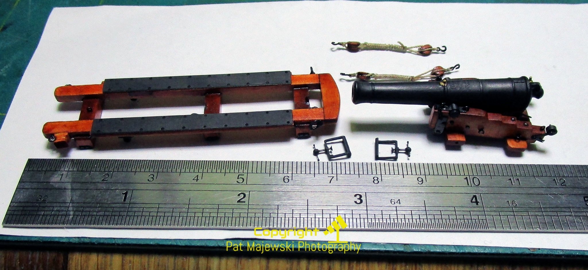
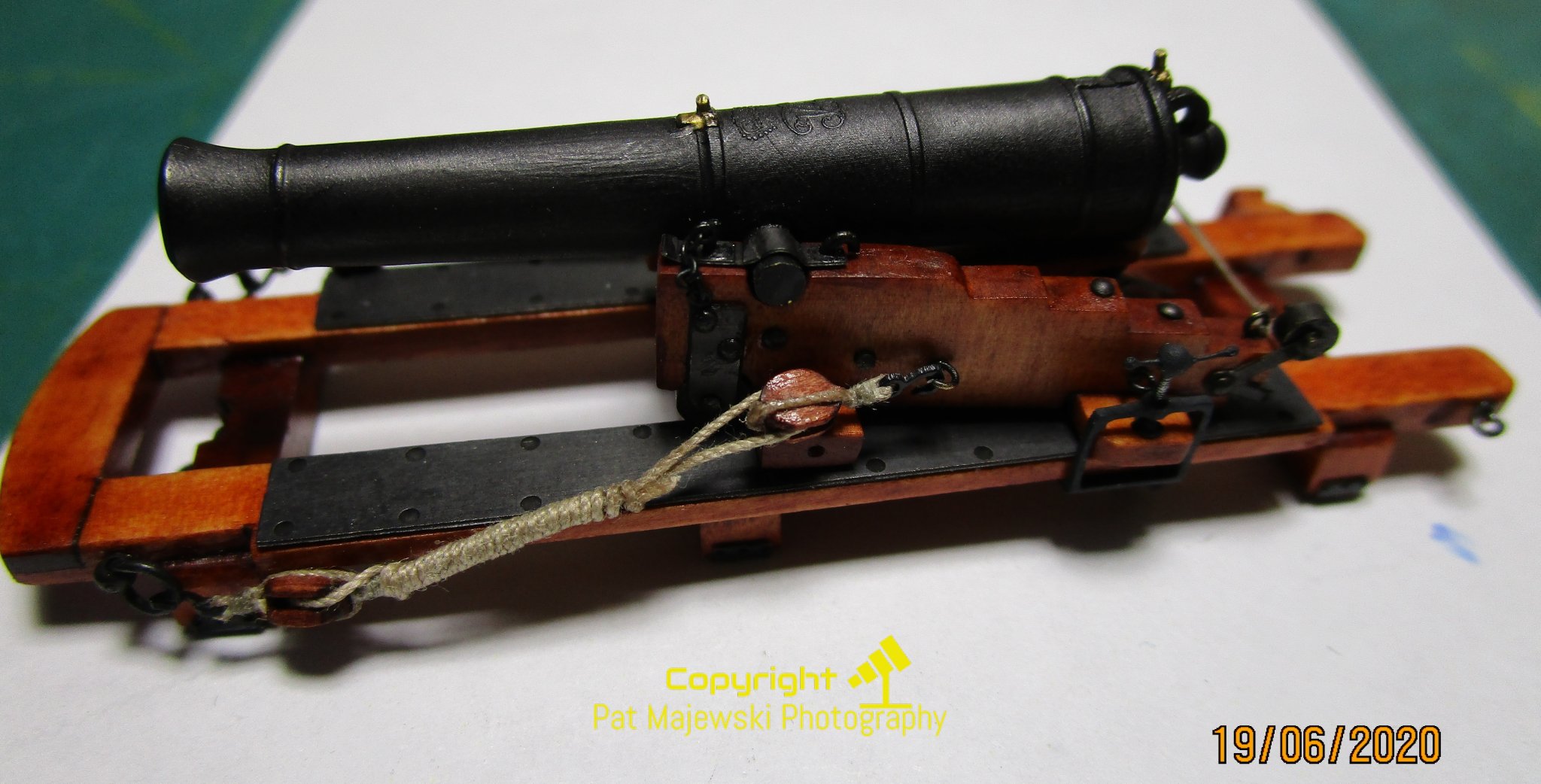
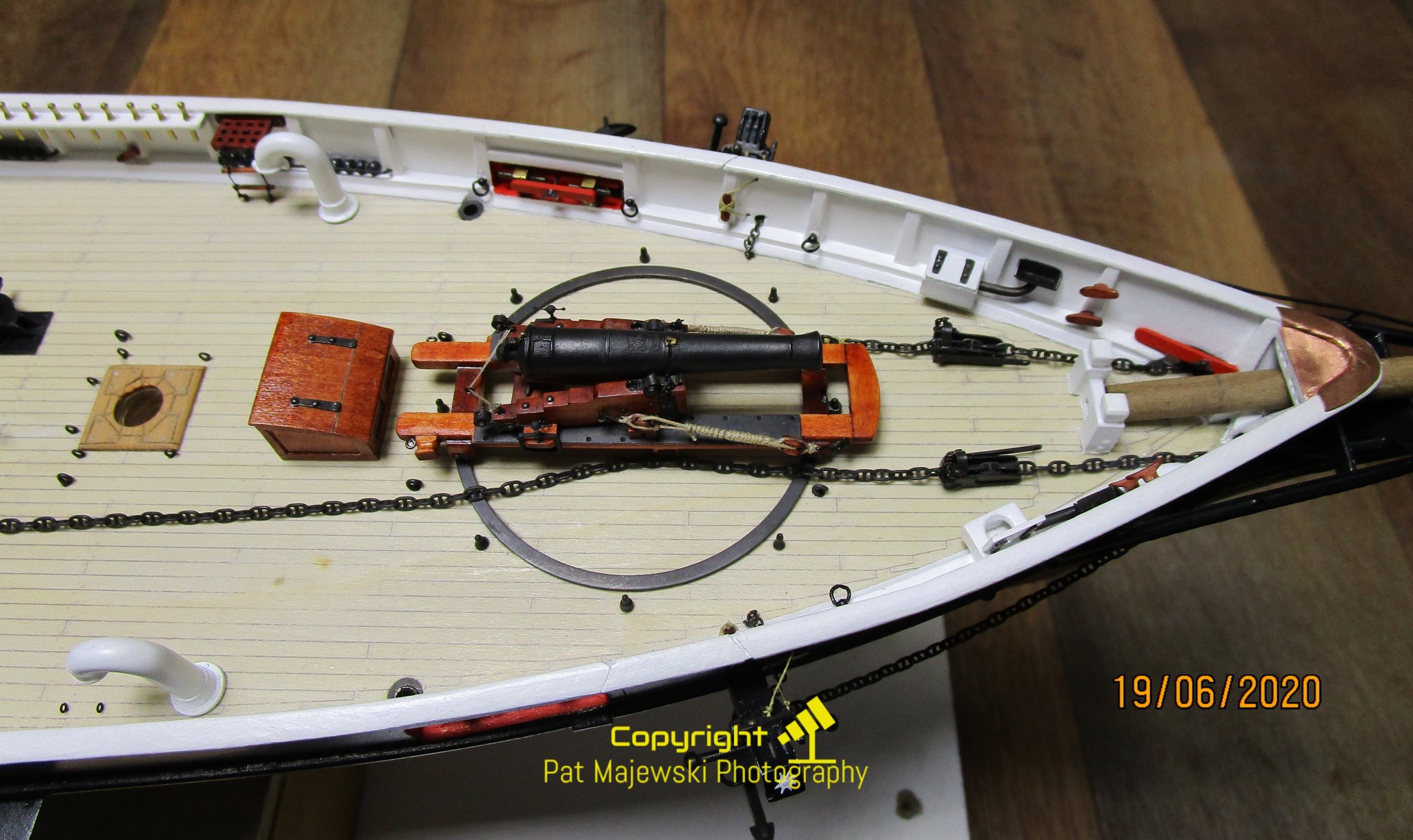
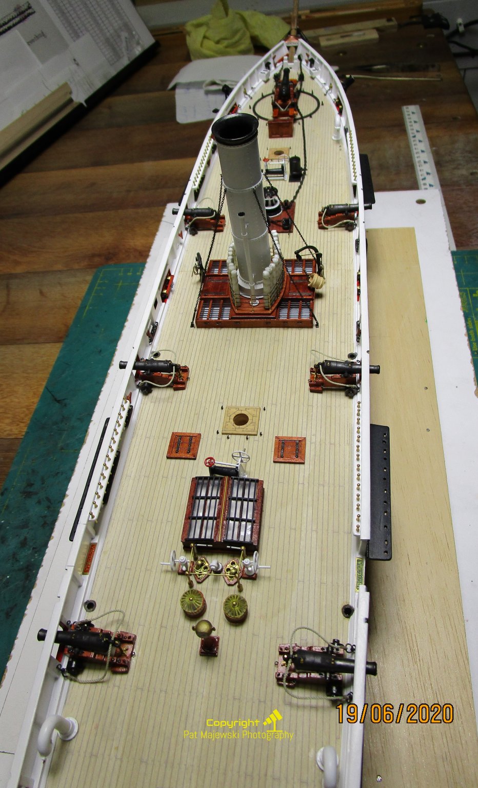
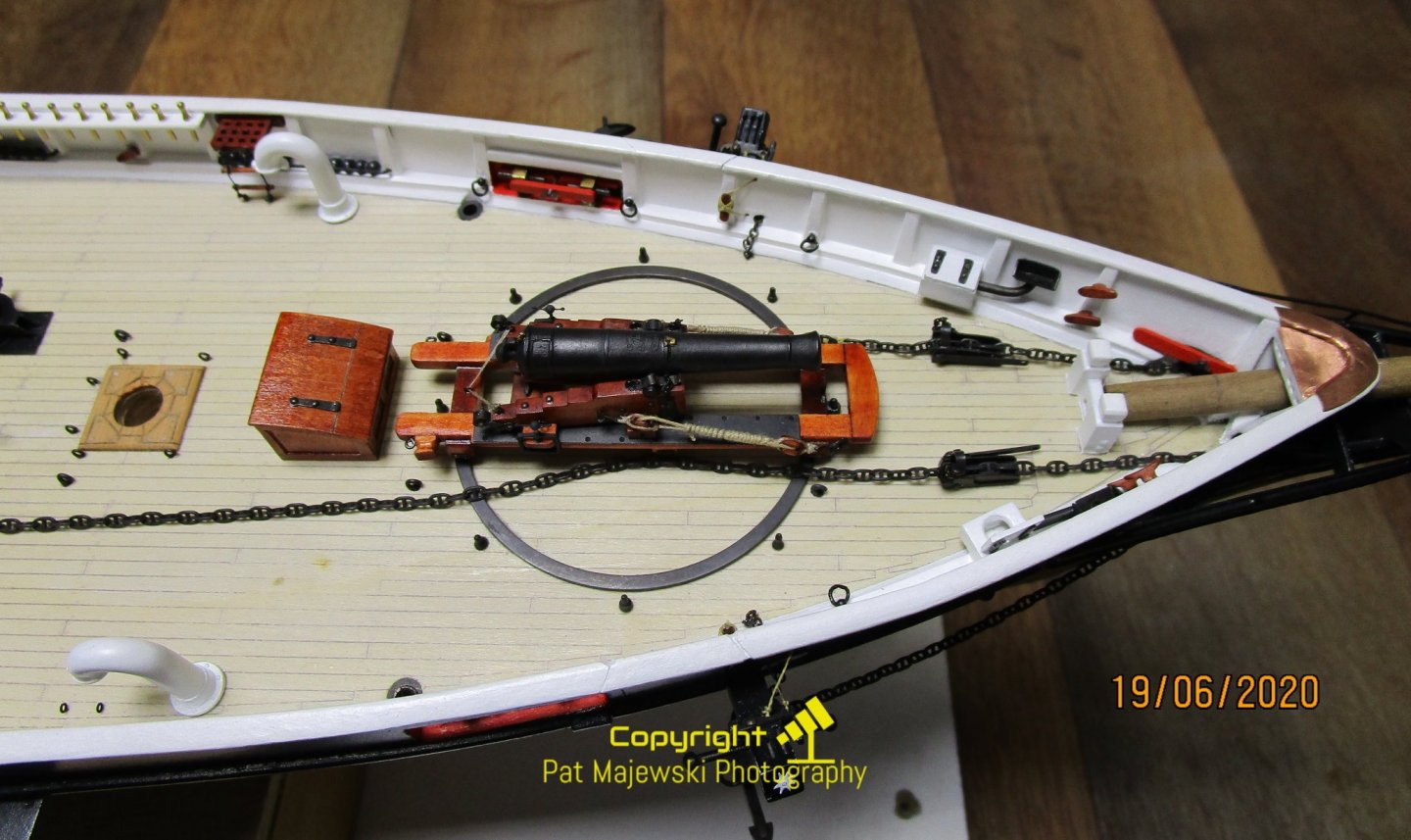
Hi folks, I have made some progress with the guns and now have them fitted (except for tackles to be added to the broadside guns. The pivot gun is now complete and shown in the stowed position; a tampion will be added soon. Note the barrel is deliberately sloped very slightly down ward to assist with drainage should any water ingress. As it is shown in the stowed position the breeching rope is not fitted, and the gun tackle used as the forward lashing; the eccentric tackles have been removed. i have left the eccentric levers 9and rollers) fitted purely to show the detail; in reality these would have been removed and stowed also. Note the size which makes the compressors very flimsy at this scale. They have been 3D printed and I hope they survive time 9and cleaning) - especially the T-Handle. The carriage fitting for the pivot gun are based on the Improved Ferguson Slide Carriage of 1847, with slight modifications based on contemporary illustrations (1855). The colour of the wood in the photos appear much more orange than they actually are. The overall shot also provides the hint of the bowsprit which I am working on now. cheers Pat


- 1,008 replies
-
- 16
-

-
- gun dispatch vessel
- victoria
- (and 2 more)
-
Another exemplar! That looks so good, take a bow Keith. Now, how are you going to etch her name in the brass I'll take a seat outside for awhile cheers Pat
-
Grey day seems to have turned into sunshine Greg, she is looking very good, but I look forward to seeing your 'rustification' process As Carl says, the deck is a little bright for wood, but I am sure you have a pl,an to tone it down a tad. cheers Pat
-
Great work Rob; don't want to visit here (post pandemic) to do a bit of rigging? (upside down as well ) cheers Pat
-
Nice planking job BW; fiddly work these clinker boats aren't they? cheers Pat
-
A very nice model that has been very well executed - Bravo Eric. cheers Pat
- 599 replies
-
- 4
-
-
- sidewheeler
- arabia
- (and 4 more)
-
It may have taken you a bit longer than you liked Stephen, but the rope work looks good. cheers Pat
-
Wow! Those overall shots, especially the one from astern look great and really show the extraordinary work you are achieving Keith. cheerrs Pat
-
For my couple of pennies worth .... I have used Sherline for some time now and find them very reliable, but..... 1. The size of the job is 'limited' so know what you intend to use it for before buying. I would also recommend the extended bed for the lathe as mentioned by several members already. A riser for the mill is optional depending on the sizes of the jobs you intend. 2. Sherline does offer 240V or 115V motor options as well as metric or Imperial; does Unimat offer these options? It depends on where you live if this should be a consideration. 3. The real issue I now experience is that the cost of Sherline accessories has gone through the roof; its almost as if Sherline know they have a cornered market. Some items are reasonable when you consider the accuracy and quality of the item, and factor in the smaller market, but other items are just plain over priced (IMHO). 4. The biggest consideration for me these days is transport costs. If you do not live in the USA, then expect to pay from two-thirds upwards the price of the item to ship it, particularly for heavier items. Unfortunately, this has now prevented me buying anything from there - I don't understand the system there as a very few suppliers (such as Chuck / Syren) still offer very reasonable postage. If you purchase from UK or Europe, things are much more reasonable (for transports related costs). All that said, I have found the Sherline very reliable and meets all my modelling related needs - I cannot comment on Unimat as I have not used them. If you can afford it, buy as many accessories as you think you will need as part of a package; not only to try and negotiate a better price, but to avoid the accumulating transport costs of acquiring the accessories individually later. cheers Pat
-
Photos of 19th century gun carriage (from coastal fort?)
BANYAN replied to Louie da fly's topic in Nautical/Naval History
Thanks for the clarification Dr Per; I thought you were referring to the gun Stephen photographed. For those interested in guns of this era, there is quite a bit of discussion by Douglas and Garbett in their respective books (both title their works 'Naval Gunnery') on the matter of how these pivot guns worked but not so much on their construction. Kemmis in his treatise on Gun Carriages also discusses the interchangeability of the carriage part and provides a little more detail on their construction. cheers Pat -
Photos of 19th century gun carriage (from coastal fort?)
BANYAN replied to Louie da fly's topic in Nautical/Naval History
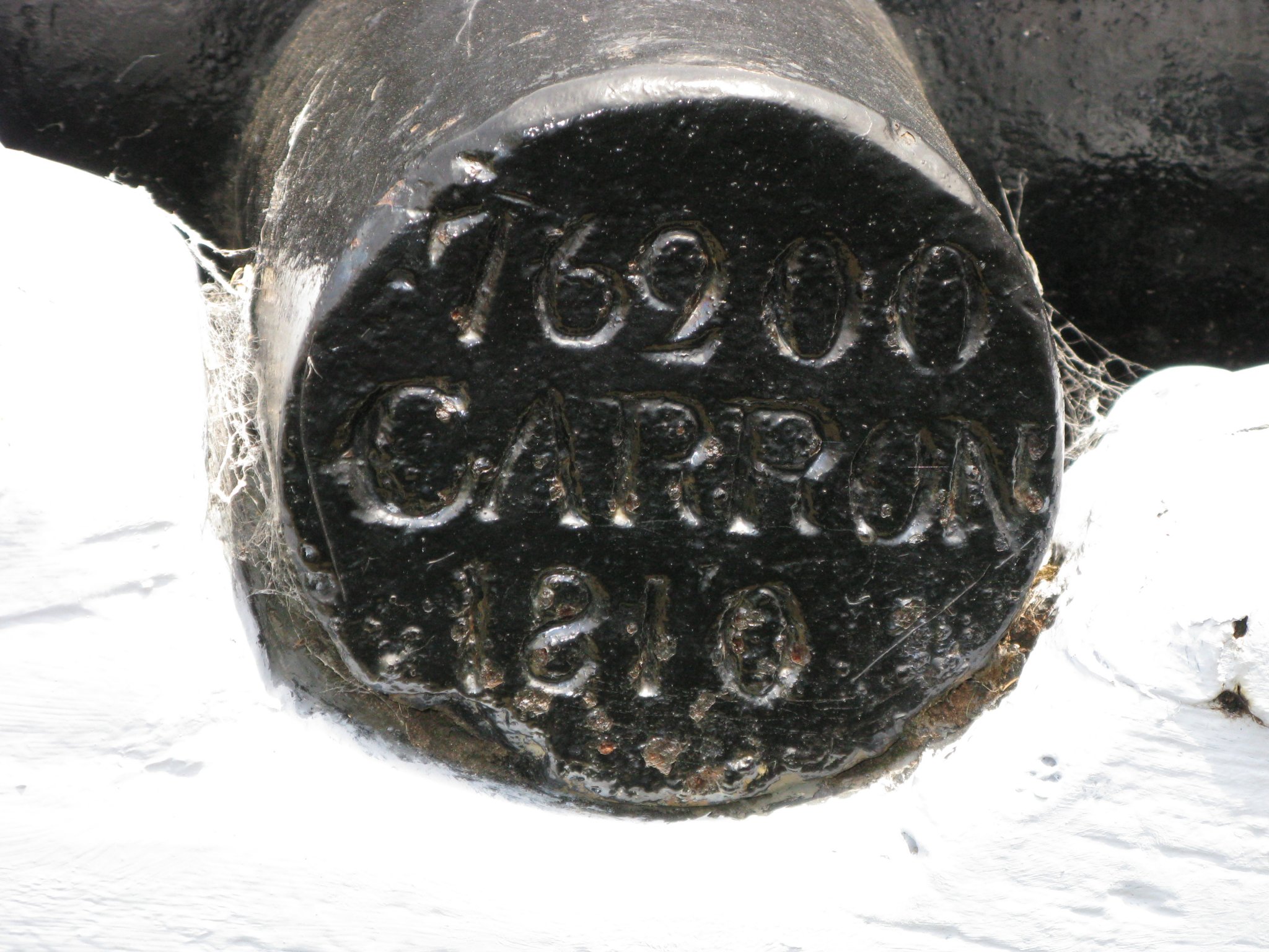
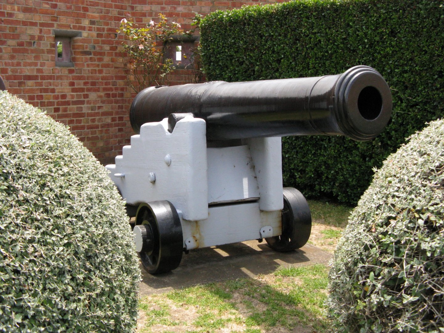
Sorry DR PR, must disagree with the wheels on the naval version of this particular gun. Naval Blomefield pivot guns were mounted on slides (Improved Ferguson Gun Slides) that had metal plates on the bottom of the transoms that ran on the racers; only the upper carriage had rollers. The shore/coastal versions did have the wheels on the slides; in the naval version the rollers/wheels did not appear until the 1860s or so. Stephen, I have a load of photos of the "original' carriage which is stored in a lean to shed at Warrnambool Museum - the curator kindly let me loose on it The gun from this mount is the one either remounted immediately to the front of the museum or up on flagstaff hill (park). I have also had a good (deep) look at all the guns in the Queenscliffe fort, and please note that they one on a common carriage placarded as being from HMCSS Victoria - is not - the sign is so wrong in many aspects. One of the researchers at the fort has done a comprehensive investigation and agrees, but the 'volunteer administration' who run the tours etc leave the sign there as it is 'more interesting' to the tour groups. Most of the guns on display around Victoria (Bendigo, Ballarat, Queenscliffe, Point Nepean, Melbourne etc,) are coastal defence versions. There is one 32-pdr 25cwt gun purported to be from the Victoria, owned by the Clunes Museum but on display at SeaWorks, Williamstown Victoria, but the provenenace of this is still to be established. This is the gun I am talking about - it is a 8ft 6 in 42cwt simply mounted on a representative common naval truck carriage. It is possible this is from HMVS Nelson which did have these as training/drill guns. As Druxey pointed out, check the markings on the guns and it is possible to determine their year of manufacture and through the records identify where some of these guns are from. The researchers at Fort Queenscliffe , and John Rogers of the "Save the Cerberus' campaign / website, have a good listing of many of these guns spread throughout Victoria. Unfortunately, HMCSS Victoria's pivot gun has yet to be located. If anyone knows....please ... cheers Pat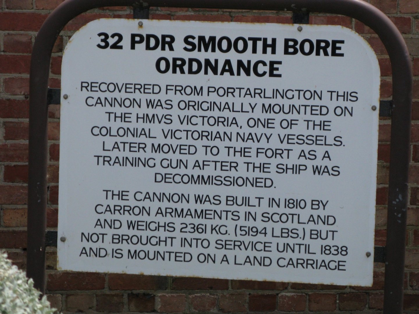

-
Hi Keith, I would be surprised if that sweep arrangement on the Alabama is correct (for the rear/after sweeps anyway). The British guns, and assuming the US gun slides also, used iron on the bottom of the slide transoms which ran on the iron sweeps (all could be bronze/gunmetal also). In the shown arrangement, the after transom could not be maneuvered correctly without damaging the decks. Even by this stage if rollers had replaced the transom plates, they would still needed sweeps. Just food for thought cheers Pat
-
Hi Stephen, I use Ritters Fabric Dye and it works well if made up and used correctly - available through Woolworths etc and dirt cheap too Give me a 'bell' and I can explain what I do. cheers Pat
-
Photos of 19th century gun carriage (from coastal fort?)
BANYAN replied to Louie da fly's topic in Nautical/Naval History
Thanks for posting Stephen. This appears to be a Blomefield 8 ft 6 in 32-pdr Casement Gun on a slide. I will need to go and have a look as it shows some interesting features . The carriage (top part) was a universal build (size etc common) such that it could just as easily be fitted to a naval slide (Casement gun slide was 16 feet whereas the naval version of the slide was only 11 feet for these 'medium' guns. The rails of the slides were the same distance apart in both versions to facilitate this cross-usage. It is more than likely that as you suggest, this is one of the many guns ordered for installing in the coastal forts for the Colony of Victoria. HMCSS Victoria (1855) was fitted with a 9ft 6 in version of this very gun. -
Thanks for the link Keith, some effort indeed. Look forward to seeing the process you use for the cowls/vents/. cheers Pat
-
Those parrot guns came up a treat Keith; nicely done. How are you determining the the sweeps for the 'races' (tracks) for these pivoting guns? Do you have a plan? I am still trying to determine these and using pivoting points based on the probable port locations as I have no plans etc. cheers Pat
-
You are really getting to grips with that laser cutter Eberhard; a very good result with the nameplates and scroll work. cheers Pat
-
Which direction do the tails of shrouds go?
BANYAN replied to Maury S's topic in Masting, rigging and sails
Thanks Justin and Allan, very useful. Maury, I hope you don't mind, bt does anyone know if this was applicable for wire rope shrouds turned on a Thimble also. I believe most wire rope was all RHL? cheers Pat -
OK, I've run out of superlatives Keith Very nice work as usual, and that overall shot of her after deck looks just like the real thing. cheers Pat
-
Fiddly it may be, but it doesn't seem to have slowed you down much - Looking good and nicely detailed. cheers Pat
-
WW2 ship drawings anyone know what this is?
BANYAN replied to Dean77's topic in Nautical/Naval History
Hi Dean, to my eye, those schematics look like a hydraulic or valve plan - i.e, shows the default configuration of valves (open or closed), where the manual and powered valves are. By hydraulic this could be water, fuel or oil. cheers Pat -
I'm not so sure PE will have looked that much better Eberhard, the effect you achieved in the second collection of photos is pretty close to the real thing - only difference being the square rather than rectangular mesh grating. Looks good to the eye (based on the photo) cheers Pat