BANYAN
-
Posts
5,965 -
Joined
-
Last visited
Content Type
Profiles
Forums
Gallery
Events
Everything posted by BANYAN
-

HMCSS Victoria 1855 by BANYAN - 1:72
BANYAN replied to BANYAN's topic in - Build logs for subjects built 1851 - 1900
Thanks again Rob, especially the encouragement. Also, thanks for looking in again Keith. I have decided to go with what the imagery is showing based on the fact it is very accurate in most regards. I have also found a comment in Underhill that 'iron' tops in wood built ships with wood masts were becoming increasingly common - but no guidance on shape, form or dimensions. I am still at odds with myself WRT to using a full iron top, wood trestletree with short wood cross-pieces supporting iron rod crosstrees, or (and my current basis) is wood trestletrees, wood short crosspieces with iron rod for the centre and after crosstress, and full wood forward crosstree with shallow wood/iron rim sitting ontop or recessed. I am drawing these up and overlaying them on the imagery to get a feel of what fits best. I think Underhill, and probably other authors do not cover this type of top as it is a radical change and probably up to the builder to construct with their own experience. Thanks all for your continued feedback; all is mot welcomed. cheers Pat- 1,021 replies
-
- 3
-

-
- gun dispatch vessel
- victoria
- (and 2 more)
-
Nice to see you back Keith. Surprising how a break turns into a sabbatical - life has its ways of distracting you! Nice work on the guns. cheers Pat
-
HMCSS Victoria 1855 by BANYAN - 1:72
BANYAN replied to BANYAN's topic in - Build logs for subjects built 1851 - 1900
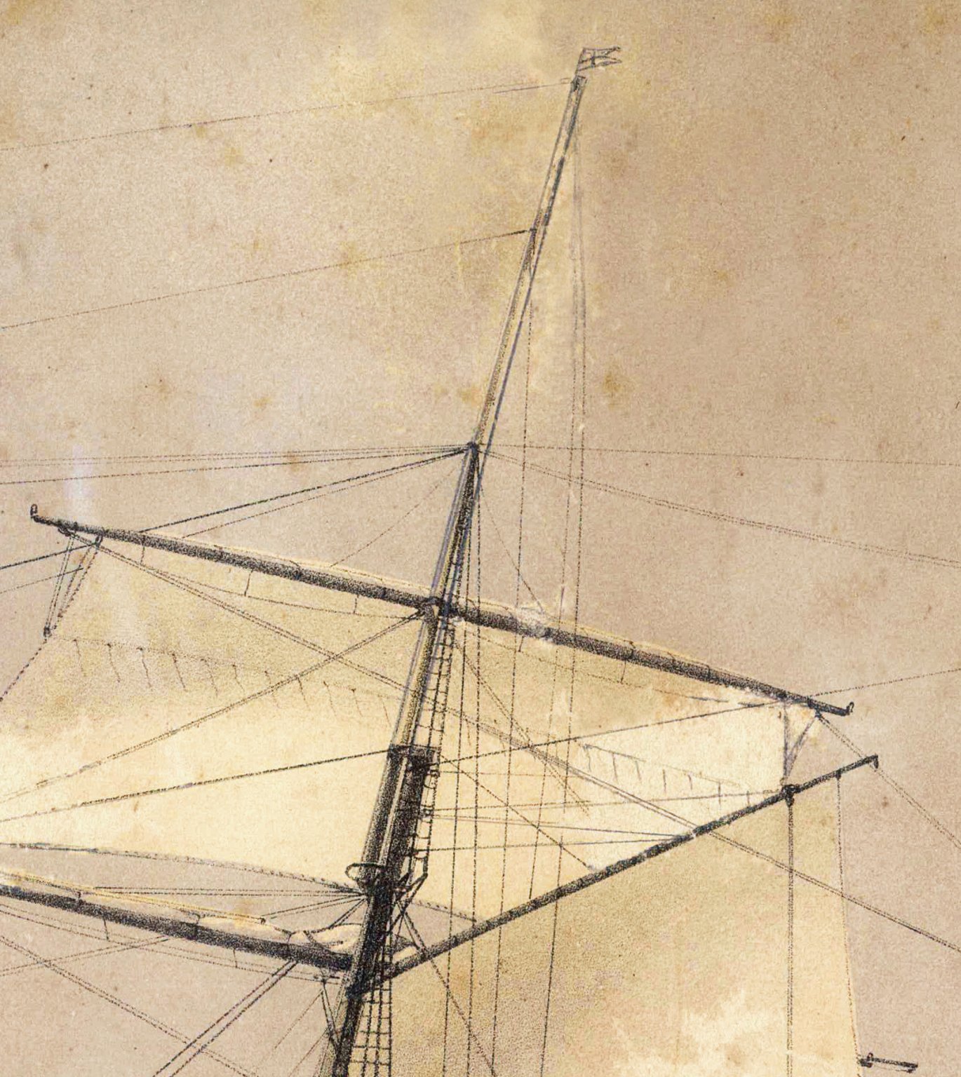
Hi again folks, as advised in my earlier post,I now having to rethink the framing of the tops in HMCSS Victoria. Based on the issues I have raised, I went back and reread most of the authors discussions about tops, and had a closer inspection of the lithographs. Having drawn up the masts IAW with the rules provided by Fincham and Kipping for forming a stick into a mast, the resulting mast when superimposed over the correctly scaled imagery (2 x lithographs and a profile photo of the ship), is an almost identical fit. The lithographers of these days were very accurate it seems. If we accept this premise, their depiction of tops must also be accurate. The tops shown in the two lithographs are both skeletal form with no gratings fitted despite the Contract (Specification) calling for them. Fincham, however, explains that the gratings were supported by metal plated fitted to the undersides of the crosstree such that they can be easily fitted or removed. Perhaps the gratings were only fitted on as required basis? More importantly, as can be seen from the attached crop of the foretop (first and mainyop, from one of these lithographs, there are two trestletrees, and based on their sizes alone, there appears to be only one full crosstree, a rim (forward), and the after two crosstrees appear to be iron rods (spreaders). The size of these latter crosstrees are not much bigger than the sizes of the topmast/futtock wire rope shrouds. Note that the trestle trees do extend aft to support these rather than battens fitted ('V' like to their tops. Underhill also explains that the use of iron in the tops, with some ships having complete iron tops, was growing more common in this era. Additionally, inspection of the image shows that in form, these tops were more akin to those fitted to the topmast than lower masts; but they still complied with the overall descriptions for the skeletal forms discussed by Kipping and Fincham as those fitted to the mastheads of steamers. My current interpretation is that the rim (elliptical crosstree) and foremost crosstree were wood, as perhaps were both trestle trees. As wooden upper masts were fitted, the usse of wood for the framing around the masthead and topmast heel will have been required to minimise damage to the timbers. Underhill also provides evidence of iron plates fitted either side of the trestletrees with a hinged iron plate across the front to support the heel of the combined top, topgallant and royal mast. He provides no guidance of how the after face of the mast head was supported, but as there was a wood fixed block fitted here between the trestletrees, for the throat halliards, that a short wood cross-pice was fitted, perhaps supported with an iron strap fitted beneath. The two after cross trees may have been simple iron rods. All that said, another option is the complete assembly was iron with wood payed to the iner surfaces of the masthead and heeling holes. My current leaning is to go with the former, but the dimensions, particularly the depth, of the trestletrees shown in the lithograph appear very small. When overlain on the lithograph it was about three to four times bigger than depicted in the lithograph. I think, in this instance, I am just going to have to wing it by drawing up the framing to conform with the lithograph. Unfortunately, Underhill (or Fincham or Kipping) does not provide any dimensioning details for iron clad, iron or any combination) thereof, and the lithograpgh shows the trestlees and crosstrees were not very large - certainly a lot smaller than the dimensions I had calculated, and drawn up, based on Kipping and Finchams' rules. I would very much welcome any further comments for or against my observations. Many thanks again for your time in looking through and commenting on this topic. cheers Pat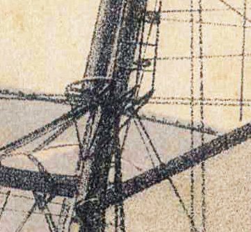

- 1,021 replies
-
- 4
-
-
- gun dispatch vessel
- victoria
- (and 2 more)
-
HMCSS Victoria 1855 by BANYAN - 1:72
BANYAN replied to BANYAN's topic in - Build logs for subjects built 1851 - 1900
Thank you all very much for your opinions and suggestions - this type of feedback is exactly what I needed. Your comments reinforce what I have been reading, or more to the point what I could not find in the reading. Kipping, Fincham, Crothers, Underhill and Harland are all silent on these particular matters. Based on these comments, I agree re use of iron fids, they were the go by this period. Unless I find better information I will retain the fid hole as cut with sides parallel with the masts heel sides (square to the heel) and perhaps add, as Druxey suggests, a beveled bottom so that the fid is flat along the bottom relative to the mast's rake. There was a iron plate set on or into (the authors differ) the upper face of the trestle trees to carry the iron fid, so that would take the weight - but Rob's advice re rounded fids intrigues me. I have seen, in Underhill I think, that a round bar preventer fid was fitted, but these did not bear the weight unless the lower (main) fid failed. Just for interest I may have a go at the diagram of forces acting on the fid suggested by Eberhard (at some point). Ed's point about readjust the rake would also impact any bevel on the fid hole iand fid is also relevant.... WRT to the stops, the overwhelming advice appears to cut them square to the mast. The point about the wire opening up with increased bending was my main concern, but It appears I may be overly concerned WRT to the mast cap, still very early days - ED, I agree these would have been square to the mast. In this case, an iron forged cap with circular openings/mortices. WRT the tops; well that is another story now - more on this later. Suffice to say, that no matter what type, the issue I am having WRT holding/securing the topmast heel remains extant. Rob, that is a great photo and shows that the gaps athwartship were of little concern as there is a reasonable gap shown in your photo. If you have any more photos of clippers or ships of this era that confirm these gaps, I would be most interested in the confirmation of the following. Fincham and Kipping advise a 1 inch allowance for play (but Fincham also says 1/4 inch elsewhere.....confusing) . This is well within the athwartship tolerance of Victoria's topmast heels - possibly of little concern as the shrouds would essentially keep it upright. The fore and aft securing though still leaves me a little confused with masts at extreme rake. Again the stays may have kept it centred once set-up; but, .... I am concerned that the rake and a flat fid would tend to try and make the mast 'skate' forward? I have also found guidance, as has been suggested by Ed, that any filling pieces are payed onto the masts and not the trees. All that said, in doing another close inspection of the imagery I now have concerns on the actual framing of these tops. I will post separately about these but the top was still set parallel to the waterline, but closer inspection shows that perhaps most of the top was made of iron. Underhill advises that this was increasingly the practice in merchant ships during this era. Many thanks again Pat- 1,021 replies
-
- 5
-
-
- gun dispatch vessel
- victoria
- (and 2 more)
-
Keith, as Wefalck has pointed out - gunmetal screwed/fitted to decks. For HMCSS Victoria they were about 3 inches high according to Douglas (Naval Gunnery 1855) I think, so I have assumed partially embeded. If I come across the correspondence again, I will post it to you but the ship build supervisor sort of infers this when talking about them. Shipman, the shore / coastal defence versions of these guns (casement guns) did run on steel or iron rails as the rollers under the slide were more like mini rail wheels, but the ship versions (with a shorter slide and flat rollers) ran on gunmetal as best I can establish. cheers Pat
- 24 replies
-
- 2
-
-
- pivot gun tracks
- pivot gun
- (and 1 more)
-
HMCSS Victoria 1855 by BANYAN - 1:72
BANYAN replied to BANYAN's topic in - Build logs for subjects built 1851 - 1900
Thanks Druxey, appreciate the feedback. WRT stops, would this have been the case even with 10 and 15 degrees of upward slop (once the masts were set-up)? That's a pretty big bend in wire rope for the stays; as I said earlier no issues for backstays, breasts and shrouds. cheers Pat- 1,021 replies
-
- 4
-
-
- gun dispatch vessel
- victoria
- (and 2 more)
-
HMCSS Victoria 1855 by BANYAN - 1:72
BANYAN replied to BANYAN's topic in - Build logs for subjects built 1851 - 1900
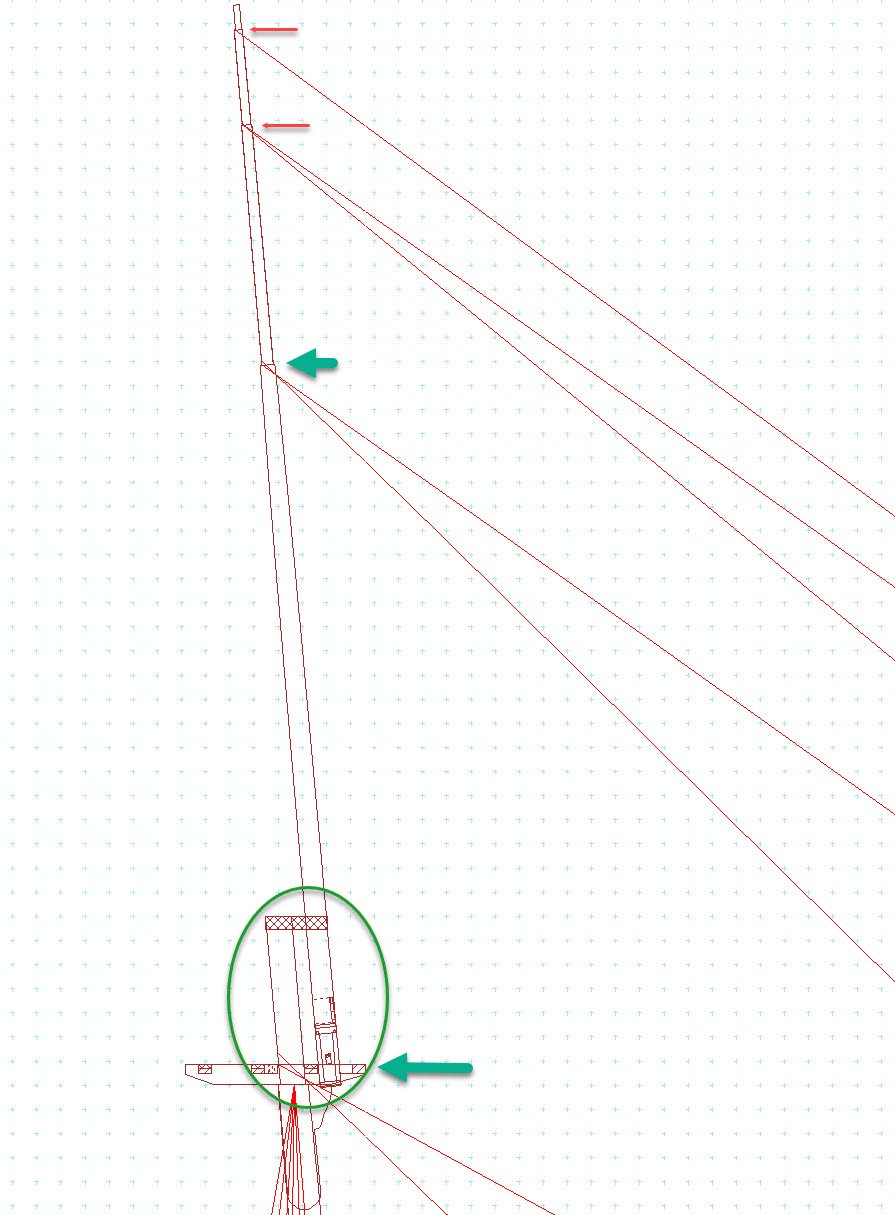
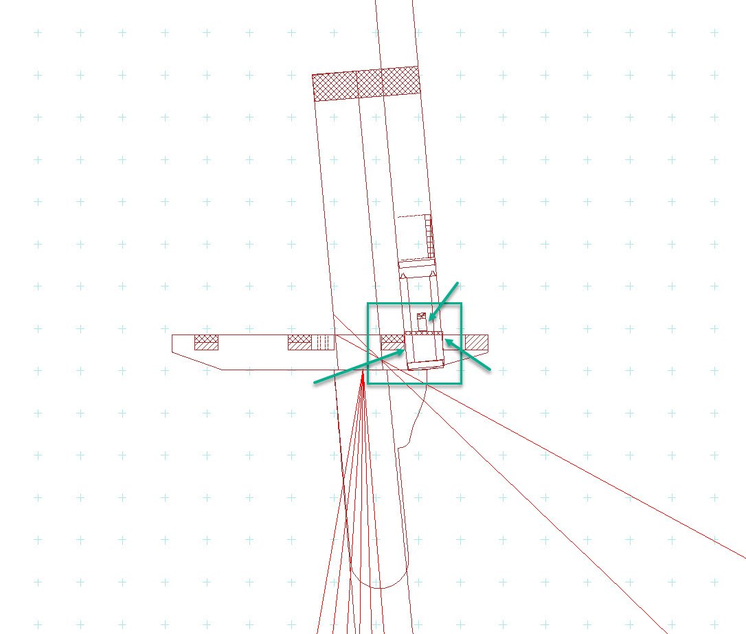
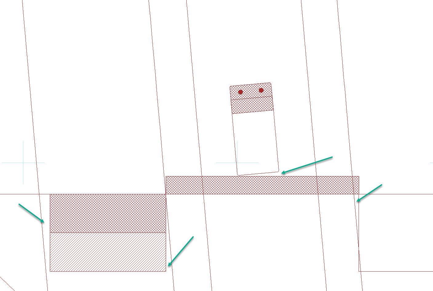
Hi again folks. Not much work done on the model in the past few weeks as I am getting into research of the spars and rigging, which is taking far more time than I thought. I am making progress though, and I need to do this before progressing as it affects the positiong, type and configuration of other equipment in the ship. As usual I have run into a few issues the more experienced may be able to assist me with? Pleeeaase! Some of these do not effect the model as such as the scale woill mask the problem, but I wish to get it righ for the drawings I am doing. Rather than flood the log with all questions at once I will 'batch' them, getting the results before moving on I hope The first batch are related and all are caused by the extreme rake in Victoria's masts (5, 10 and 15 degrees for the Fore, Main and Mizen masts respectively.) The problems listed below all relate to the various contemporary and more recent authors discussing the masts as if the stand vertical. That is, the stops, tops etc asre all cut or placed as if the mast is not raked and no guidance is offered for what to do when they are raked aft (except for the tops which we know are placed horizontal or parallel to the waterline.) Please see attached drawings where I have tried to illustrate the issues. Cross hatch is ironwork including a 1 inch fid plate fitted on top of the trestle trees. The diagonal hatch represents the ends of timbers. Please look closely as the drawing of the top as gaps are small but evident as is the misaligned fit of the heel (slanted) into the squared hole for the heeling. The small unhatched piece is a 'small cross-piece' that sits behind the rim. Again the guidance infers to make this square on its after face. I can move the rim forward a bit which fixes the overlap at the forefoot of the topmast heel; but opens the gap. The larger gap abaft the crosstree is there by design, as the Kipping and Fincham adise a 1" allowance was made here (assumed to allow the upper mast (long pole) to pass through due to the rake of these masts. Q1. Should the stops (no hounds) for the upper mast be cut horizontal also? If not, as the standing rigging (wire rope) have eyes seized to fit snug/tight on the stop, the backstays would, and perhaps the shrouds may, lead fair, BUT the forestays would have a large kink induced as , say for the main mast, they would point 10 degrees into the sky (vertical) before bending down. My gut feel is they should also be parallel to the waterline but cannot find any guidance on this. Q2. AS the top, and therefore the crosstrees are fitted parallel to the waterline, but the upper mast is set-up at an angle corresponding the the relevant mast's rake, it would not sit up-and-down in the hole framed between the trestletrees and crosstrees. The imagery shows that the foremost crosstree passed between the lower masthead and heel of the upper mast (combined pole including top, topgallant and royal masts). This would mean this crosstree would sit square (true up-and-down) having been let into the trestletrees, whereas the masthead and heel would be raked. This results in only a part of the crosstree fore and after faces providing support (sides are not an issue). The contemporary practice was to use a shaped chock here (instead of a crosstree) but that was for a standard top (larger and fully made with a platform, battens etc) The tops in Victoria are unlike in any other ship I have seen, and, in form, were more like the tops used at the topmast hounds where loose masts were fitted. Even here, the guidance shows squared crosstrees. Simply fitting a wedge would not work. My only solution might be to fit/fay a shaped filling piece on the fore side of the masthead, and after face of the heel to square the resulting gaps (hope that makes sense) The issue there though is that increases the distance between the crosstrees much more than what is shown in the imagery. Such filling pieces were used to remove excessive 'play' of the heel but were usually evenly sized in section (not sloping/wedge shaped). Any ideas? Q3. Similar to the issue with the stops, it would appear to be sensible to adjust the fid holes tosuch that the fid would sit flush on the trestletree. Again all auther say this is cut in parallel to mast sides, but does not make sense for mastes that are raked. Do I agjust these to up-and-down? Would this weaken the fid or holding power as the centre of force (weight) is now not acting direct through the fid. Any help, suggestions, pointers etc most welcomed. cheers Pat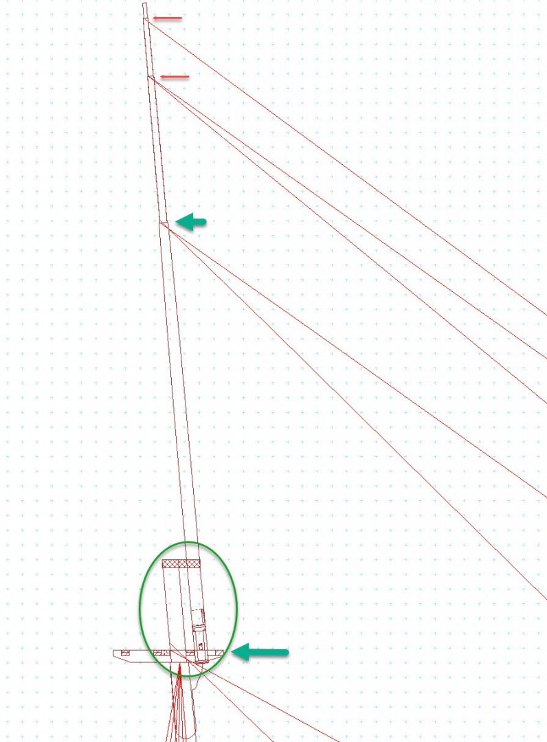
- 1,021 replies
-
- 9
-
-
- gun dispatch vessel
- victoria
- (and 2 more)
-
Hi Richard, they were not necessarily made of iron. I am researching a ship of the same era with a pivot gun that used sweeps such as these - they were made of gunmetal. That is not to say they were not iron, they may well have been - need more info I think. Good luck with the build Alan, cheers Pat
- 24 replies
-
- 3
-
-
- pivot gun tracks
- pivot gun
- (and 1 more)
-
Just caught up with your log Brain; congratulations on a very fine build - especially noting this is your first scratch build. Looking forward to seeing your progress. cheers Pat
-
That is starting to look like a very nice set of hull lines Rob. cheers Pat
- 3,560 replies
-
- 2
-
-
- clipper
- hull model
- (and 2 more)
-
It might take you hours Eberhard but the level of detail you achieve is extraordinary for that scale. If you can spare a little of your time, can you explain the watchmaking staking jig/rig you use? Stay safe Pat
-
That crew looks great Steven, you had set your self quite a task and achieved the desired outcome very well. As a coincidence, I was looking at a documentary called 'The Real Bjorn Ironsides' last night and about half way, and three quarters the way through they popped up a picture of a dromon (same one) - not sure if it would help you. It is supposed to be one built in Spain for the protection of their cities when the vikings came raiding. cheers Pat
-
Hank, this was very much hit and miss when I was researching but I did have some success in searching on equipment manufacturer sites or their pdf/electronic brochures - need to know the name of the companies that produced them though? n Yopu may have already tried that, but thought I would raise it just in case. Good luck Pat
-
That's looking mighty fine there Rob, I think you are close to nailing it (no pun intended) cheers Pat
- 3,560 replies
-
- 2
-
-
- clipper
- hull model
- (and 2 more)
-
Hydraulic Dredge by Steve Harvath
BANYAN replied to Steve Harvath's topic in - Build logs for subjects built 1851 - 1900
Just happened on your build Steve. A very interesting subject to model and you are doing a grand job with her. cheers Pat -
A very fine job on the crew Steven, the model is looking superb (even close up). I have been refraining but just can't help myself - the crew may have been 'armless' but at least they weren't 'legless' - quite the sober lot! cheers Pat
-
I have to agree with Steven; very nice work on putting the planking together. cheers Pat
- 158 replies
-
- 1
-
-
- byblos ship
- Egyptian
- (and 1 more)
-
Looks good Greg. These are becoming too easy for you I think as you are building them so quickly - you should to return to wood for a challenge cheers Pat
- 136 replies
-
- 4
-
-
- strasbourg
- finished
- (and 2 more)
-
I have been following this with interest Rob, looks like you and the other contributors are slowly getting a grip on the hull form. cheers Pat
- 3,560 replies
-
- 2
-
-
- clipper
- hull model
- (and 2 more)
-
Looks like you have achieved a good form for your planking to go onto Mark; happy sawdust making. cheers Pat
-
You're quite the wiz-kid with PE now Greg; didn't take you long to put that complex lot together. Some very nice detail there. cheers Pat
- 136 replies
-
- 5
-
-
- strasbourg
- finished
- (and 2 more)
-
Your crew are looking in good form, must have a good skipper? Steven, not trying to be funny here but with your skills, have you considered building that background as a 'facade' - a la movie prop? More work I know and you may wish to move onto other things but you could hang it with more shields cheers Pat
-
A very creditable job Hellmuht, especially noting the small amount of glue used. cheers Pat
- 158 replies
-
- 1
-
-
- byblos ship
- Egyptian
- (and 1 more)