BANYAN
-
Posts
5,961 -
Joined
-
Last visited
Content Type
Profiles
Forums
Gallery
Events
Everything posted by BANYAN
-
 Dick, when I was building my Endeavour I tried using under car bitumen coating on the lower hull. It went on well and dried to a nice even coating looking very much like a coating of 'brown stuff' - BUT, that was in winter , then along came summer, and while not making the bitumen slump, it got very tacky. So, off it came - but the surprise was that were the tar in the coating had penetrated the gaps, cracks etc in the lower hull planking, it left a very nice effect that showed a distinct darker shade under and above the waterline. Just saying - maybe a light wash that just darkens it while retaining the definition of your planking etc? That hull is looking very good and as Steven says, it would be a pity to cover it. cheers Pat
 -
Love the see-saw Steven - seriously though, that is some very nicer work and makes the ship so much more realistically displayed. cheers Pat
-
Another very interesting subject you are modelling here Dick. I have been lurking on this topic so thought I had better join the crowd before the pop-corn runs out ( I would settle for a pack of maltesers though ) cheers Pat
- 186 replies
-
- 2
-

-
- keelless
- reverse clinker
- (and 4 more)
-
Just found you build Allan, a very nice subject and you model is doing her real justice. cheers Pat
-
Impressive work; love the jig you used for the wheel. Great idea for the lanterns also; very effective results. cheers Pat
-
Looks great. You must be close to using more twine than wood in this model soon cheers Pat
- 158 replies
-
- 2
-
-
- byblos ship
- Egyptian
- (and 1 more)
-
Great to see you back Keith, even on a part-time basis. Look forward to your updates. cheers Pat
-
Add a smidge here, take off a tad there and hey presto Just need to tie a few parts together with fencing wire and you will have a true Aussie creation cheers Pat
-
Another interesting subject to model Greg. Despite the heavy dependence on after-market parts to dress her up, the hull itself seems like if is fairly well defined for her armour panels and the like? cheers Pat
-
She's looking great Hellmuht; a very nice job you have done on the stitching. Must have taken some time to work out the repeating pattern to achieve the look? cheers Pat
- 158 replies
-
- 1
-
-
- byblos ship
- Egyptian
- (and 1 more)
-
Hi again all, Keith, as promised, I have found the reference but had the wrong author. The book 'Naval Gunnery' by Captain H. Garbett, page 66, states that pivot guns were traversed on gun-metal racers (sweeps) secured to the deck. Note the wording which he uses in his book, which says secured to the deck, NOT into the deck. This book was first published in 1897, the copy I refer to is the 1971 reprint. Hope this helps. cheers Pat
- 24 replies
-
- 3
-
-
- pivot gun tracks
- pivot gun
- (and 1 more)
-
Not sure if directly applicable Rob, but WRT the plates, HMCSS Victoria's Contract required the builder to be redock the ship (at their expense) for sheathing after completely fitting out - probably to ensure a very clean bottom on delivery. cheers Pat
- 3,560 replies
-
- 3
-
-
- clipper
- hull model
- (and 2 more)
-
Stunning work as usual Amalio, a feast for the eyes. cheers Pat
-
The revised castles look good Steven, I might even suggest the core structure look even better. Moving them to better accommodate the rowers was also a very wise choice. Not too much any 'rivet counters' could find to fault in your model cheers Pat
-
That's a very nice painting Rob, and as you say sits very nicely in your themed library - quite the cosy snug uou have there! cheers Pat
-
HMCSS Victoria 1855 by BANYAN - 1:72
BANYAN replied to BANYAN's topic in - Build logs for subjects built 1851 - 1900
Thanks for looking in Tony. Well.......... the reason there has been no progress shown is that I have made none. Before I can progress further I need to get the spars and rigging sorted and drawn up. The issue as you can see from the above discussion is that so much of this is inter-related - i.e the size of one thing determined the size of another etc. Until I get those finalised, I can't start on making the spars, which in turn governs some of the belaying of the rigging, which in turns governs the positions of the bitts, some pin rails/cross-pieces etc etc. Well I am sure you get the picture. As soon as I have sorted these tops I think I am in a position to finalise the spars. cheers Pat- 1,017 replies
-
- 6
-
-
- gun dispatch vessel
- victoria
- (and 2 more)
-
HMCSS Victoria 1855 by BANYAN - 1:72
BANYAN replied to BANYAN's topic in - Build logs for subjects built 1851 - 1900
Thanks Rob, appreciate the thumbs up and you have encapsulated my delema nicely in those two approaches. My first attempt was to use the most current general conventions/building practices written by Fincham and Kipping, whom both released books on Masting and Rigging ships in 1855 (the year Victoria was built). This resulted in a top that is WAY oversized -nearly thre to four times bigger than what is shown in imagery. I agree with you WRT the builders using their own methods and designs, but unfortunately, as far as I know this was not recorded by the Victoria's builders. I live in the hope that when I can get back into the Public Records Office (once we get out of lock downs etc) and complete my investigations into the correspondence from and to the ship build supervisor (who wrote weekly build progress reports for the Governor of Victoria - a naval offer so the reports are in depth and about the appropriate matters - not just fancy words and 'fluff'). Underhill, as I have said, does advise that it was becoming increasingly more common to use iron in the tops. I am now reading him from cover-to-cover rather than selections based on the current item I am working on. As a result, I am now almost sure that Victoria will have used iron hounds and tops. Unfortunately, he, Fincham, Kipping Crothers nor Lees gives any guidance on these; so I will have to cast my net wider. I am now to trying to find anything that will help me in drawing up a set of completely iron tops and hounds. Thanks for all the 'thumbs-up' and looking in folks, much appreciate the interest in this subject matter. Cheers Pat- 1,017 replies
-
- 2
-
-
- gun dispatch vessel
- victoria
- (and 2 more)
-
Hydraulic Dredge by Steve Harvath
BANYAN replied to Steve Harvath's topic in - Build logs for subjects built 1851 - 1900
A very authentic looking model Steve; take a bow. cheers Pat -
Continuing to enjoy your build Dick, and the temptation remains - I just have to be realistic about it. I still have the Victoria to finish (just experienced a major set-back in researching her spars, finish a restoration.....) - well I am sure you know the story Steven - what can I say - naughty, naughty Dick, have you no shame? cheers Pat
-
Nice fix on the xylokastra Steven; as Druxey says; probably a small bonus in that the real thing may have need that extra structural support from below anyway. WRT threads, there are a number of good suppliers here in Oz online with colour charts etc available - give me a call if you need details. That said, the final mixture and method you used produced excellent results. cheers Pat
-
Very nice work on the guns Greg; they look great. What brands of paint are you using for airbrushing these? cheers Pat
- 136 replies
-
- 4
-
-
- strasbourg
- finished
- (and 2 more)
-
HMCSS Victoria 1855 by BANYAN - 1:72
BANYAN replied to BANYAN's topic in - Build logs for subjects built 1851 - 1900
Thanks again Rob, especially the encouragement. Also, thanks for looking in again Keith. I have decided to go with what the imagery is showing based on the fact it is very accurate in most regards. I have also found a comment in Underhill that 'iron' tops in wood built ships with wood masts were becoming increasingly common - but no guidance on shape, form or dimensions. I am still at odds with myself WRT to using a full iron top, wood trestletree with short wood cross-pieces supporting iron rod crosstrees, or (and my current basis) is wood trestletrees, wood short crosspieces with iron rod for the centre and after crosstress, and full wood forward crosstree with shallow wood/iron rim sitting ontop or recessed. I am drawing these up and overlaying them on the imagery to get a feel of what fits best. I think Underhill, and probably other authors do not cover this type of top as it is a radical change and probably up to the builder to construct with their own experience. Thanks all for your continued feedback; all is mot welcomed. cheers Pat- 1,017 replies
-
- 3
-
-
- gun dispatch vessel
- victoria
- (and 2 more)
-
Nice to see you back Keith. Surprising how a break turns into a sabbatical - life has its ways of distracting you! Nice work on the guns. cheers Pat
-
HMCSS Victoria 1855 by BANYAN - 1:72
BANYAN replied to BANYAN's topic in - Build logs for subjects built 1851 - 1900
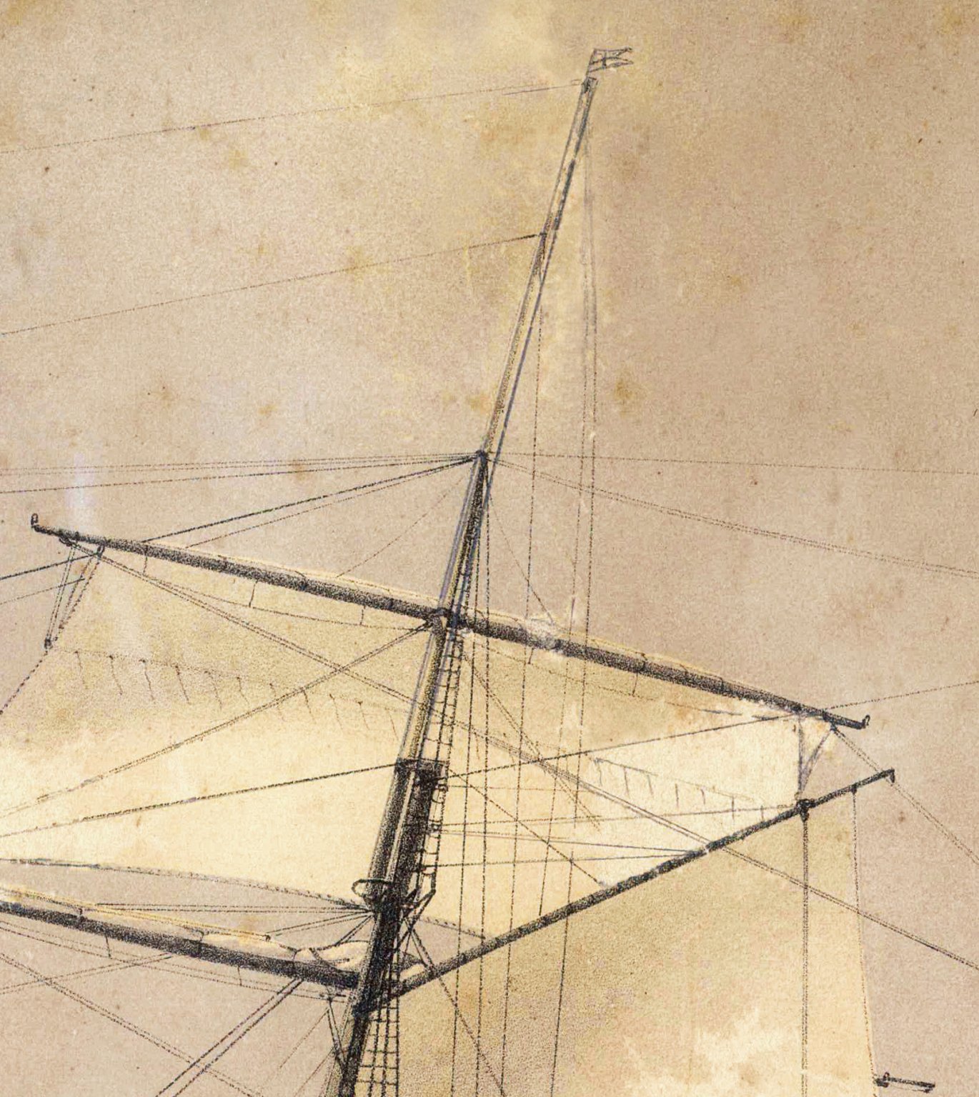
Hi again folks, as advised in my earlier post,I now having to rethink the framing of the tops in HMCSS Victoria. Based on the issues I have raised, I went back and reread most of the authors discussions about tops, and had a closer inspection of the lithographs. Having drawn up the masts IAW with the rules provided by Fincham and Kipping for forming a stick into a mast, the resulting mast when superimposed over the correctly scaled imagery (2 x lithographs and a profile photo of the ship), is an almost identical fit. The lithographers of these days were very accurate it seems. If we accept this premise, their depiction of tops must also be accurate. The tops shown in the two lithographs are both skeletal form with no gratings fitted despite the Contract (Specification) calling for them. Fincham, however, explains that the gratings were supported by metal plated fitted to the undersides of the crosstree such that they can be easily fitted or removed. Perhaps the gratings were only fitted on as required basis? More importantly, as can be seen from the attached crop of the foretop (first and mainyop, from one of these lithographs, there are two trestletrees, and based on their sizes alone, there appears to be only one full crosstree, a rim (forward), and the after two crosstrees appear to be iron rods (spreaders). The size of these latter crosstrees are not much bigger than the sizes of the topmast/futtock wire rope shrouds. Note that the trestle trees do extend aft to support these rather than battens fitted ('V' like to their tops. Underhill also explains that the use of iron in the tops, with some ships having complete iron tops, was growing more common in this era. Additionally, inspection of the image shows that in form, these tops were more akin to those fitted to the topmast than lower masts; but they still complied with the overall descriptions for the skeletal forms discussed by Kipping and Fincham as those fitted to the mastheads of steamers. My current interpretation is that the rim (elliptical crosstree) and foremost crosstree were wood, as perhaps were both trestle trees. As wooden upper masts were fitted, the usse of wood for the framing around the masthead and topmast heel will have been required to minimise damage to the timbers. Underhill also provides evidence of iron plates fitted either side of the trestletrees with a hinged iron plate across the front to support the heel of the combined top, topgallant and royal mast. He provides no guidance of how the after face of the mast head was supported, but as there was a wood fixed block fitted here between the trestletrees, for the throat halliards, that a short wood cross-pice was fitted, perhaps supported with an iron strap fitted beneath. The two after cross trees may have been simple iron rods. All that said, another option is the complete assembly was iron with wood payed to the iner surfaces of the masthead and heeling holes. My current leaning is to go with the former, but the dimensions, particularly the depth, of the trestletrees shown in the lithograph appear very small. When overlain on the lithograph it was about three to four times bigger than depicted in the lithograph. I think, in this instance, I am just going to have to wing it by drawing up the framing to conform with the lithograph. Unfortunately, Underhill (or Fincham or Kipping) does not provide any dimensioning details for iron clad, iron or any combination) thereof, and the lithograpgh shows the trestlees and crosstrees were not very large - certainly a lot smaller than the dimensions I had calculated, and drawn up, based on Kipping and Finchams' rules. I would very much welcome any further comments for or against my observations. Many thanks again for your time in looking through and commenting on this topic. cheers Pat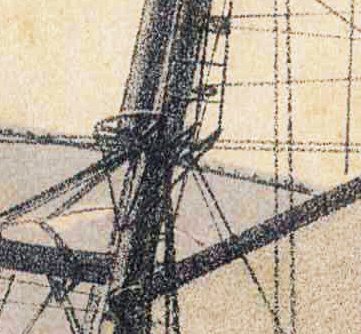

- 1,017 replies
-
- 4
-
-
- gun dispatch vessel
- victoria
- (and 2 more)
-
HMCSS Victoria 1855 by BANYAN - 1:72
BANYAN replied to BANYAN's topic in - Build logs for subjects built 1851 - 1900
Thank you all very much for your opinions and suggestions - this type of feedback is exactly what I needed. Your comments reinforce what I have been reading, or more to the point what I could not find in the reading. Kipping, Fincham, Crothers, Underhill and Harland are all silent on these particular matters. Based on these comments, I agree re use of iron fids, they were the go by this period. Unless I find better information I will retain the fid hole as cut with sides parallel with the masts heel sides (square to the heel) and perhaps add, as Druxey suggests, a beveled bottom so that the fid is flat along the bottom relative to the mast's rake. There was a iron plate set on or into (the authors differ) the upper face of the trestle trees to carry the iron fid, so that would take the weight - but Rob's advice re rounded fids intrigues me. I have seen, in Underhill I think, that a round bar preventer fid was fitted, but these did not bear the weight unless the lower (main) fid failed. Just for interest I may have a go at the diagram of forces acting on the fid suggested by Eberhard (at some point). Ed's point about readjust the rake would also impact any bevel on the fid hole iand fid is also relevant.... WRT to the stops, the overwhelming advice appears to cut them square to the mast. The point about the wire opening up with increased bending was my main concern, but It appears I may be overly concerned WRT to the mast cap, still very early days - ED, I agree these would have been square to the mast. In this case, an iron forged cap with circular openings/mortices. WRT the tops; well that is another story now - more on this later. Suffice to say, that no matter what type, the issue I am having WRT holding/securing the topmast heel remains extant. Rob, that is a great photo and shows that the gaps athwartship were of little concern as there is a reasonable gap shown in your photo. If you have any more photos of clippers or ships of this era that confirm these gaps, I would be most interested in the confirmation of the following. Fincham and Kipping advise a 1 inch allowance for play (but Fincham also says 1/4 inch elsewhere.....confusing) . This is well within the athwartship tolerance of Victoria's topmast heels - possibly of little concern as the shrouds would essentially keep it upright. The fore and aft securing though still leaves me a little confused with masts at extreme rake. Again the stays may have kept it centred once set-up; but, .... I am concerned that the rake and a flat fid would tend to try and make the mast 'skate' forward? I have also found guidance, as has been suggested by Ed, that any filling pieces are payed onto the masts and not the trees. All that said, in doing another close inspection of the imagery I now have concerns on the actual framing of these tops. I will post separately about these but the top was still set parallel to the waterline, but closer inspection shows that perhaps most of the top was made of iron. Underhill advises that this was increasingly the practice in merchant ships during this era. Many thanks again Pat- 1,017 replies
-
- 5
-
-
- gun dispatch vessel
- victoria
- (and 2 more)