


Snug Harbor Johnny
-
Posts
1,508 -
Joined
-
Last visited
Content Type
Profiles
Forums
Gallery
Events
Everything posted by Snug Harbor Johnny
-
 Ahoy! The supplied planking does look a nit thick for the scale of the kit... but you can still 'plug away' to get used to working with wood. (The rigging will be a challenge unless your deadeyes and blocks are larger than for scale.) One thing that can help you 'fair' there hull is to glue balsa or basswood 'filler blocks' between the frames (bulkheads), and then plane/shave/sand down to the level of the frames so the hull curvature is smooth. If any frame is to low (as the smooth form develops ... note that you should bot be planking until the hull is faired), strips of wood can be glued to the edge off the frame to 'bring it up' to the needed level. When planking, get some wood strips around half the apparent thickness of what we see in the photos. You can soak a little (not too long), heat with an iron or blow drier, and rough bend the plank while still warm. There are several logs showing alternative planking techniques. Since you will be painting the hull, don't fret about 'perfect planking', but get your feet wet in the building process. You can likely have a nice 'standoff scale' model when done. I can recommend the Endurance by OcCre (Shackleton's ship), which could be a good 'next step' There is a review of the kit in the kit review section, and a complete build by HakeZou, plus a build in progress by Clearway. Don't worry about kit modifications, as you can build it 'out of the box' and get a very nice model - in approximately 1:72 scale. The building and rigging is much easier in this scale. The instructions are pretty good AND there is a video on line made by the kit manufacturer showing EVERY step of building it ... nearly in 'real time' (some breaks for repetitive actions). There are no guns (thus no gun ports and tackle) needed, no need to copper the hull - as the original was painted with newly popular anti-fouling paint (rust red). There are many pictures of the original on line if you want to look. Only the fore mast has square sails, as the other two are fore-and-aft rigged - a real time saver. And there are now a few picture available on line of the actual ship as she lays on the bottom in Antarctic water. Best of luck ! Johnny
 -
Ahoy Dave ! I just received the Underhill Clipper book (great condition other than some clear tape to reinforce the paper jacket) priced at $27 and change (plus $5 shipping) - and it is an excellent investment, possibly tied for the best rigging book I've found to date. It was certainly great advice from Rob Reiderrich, who is justifiably a clipper 'guru'. When one takes ALL the detail into account, I can see why undertaking a clipper project smaller in scale than 1:96 is not practical unless one omits or simplifies a few things. But there are well rendered builds at 1:96 and larger with virtually all the 'bells and whistles'. There are an arguments in favor of building an 'early' clipper (e.g. the Sea Witch of 1846 - prior to significant changes in her rig post 1850) ... 1.) The hull length is 40+ feet shorter than the Cutty Sark or Thermopylae, so a 1:72 scale will about about the same size as a 1:96 version of the other ships named. 2.) This was prior to Howe's split top sails (or split top gallant that is seen on later clippers), so the early ships sported four sails per mast (as seen on contemporary artwork) instead of the 6 sails often seen on later ships. 3.) The masting and sparring was all wood on the early ships, and there were fewer complex metal fittings that would arise as the art of the clipper developed. An interesting note is made in Underhill's book (which he admits focuses on the later clippers - often having steel hulls), on page 163 which talks about bunt lines ... There is a variation clearly shown (fig.150 on the same page) where two bunt lines can be worked with a single running line (via two 'helper' single blocks rigged to the shroud above the yard). That way, the number of lines having to go through fairleads and down to belaying pins on bulwark pin rails can be significantly reduced. The 'more common' way is to have every bunt line find its way down as shown in plate 34 (page 188) ... a veritable 'jungle' of lines below the the course (main sail). For a modeler's sanity, the leech lines (one on either side of each sail) might be omitted, but the reef tackle should remain. One can also consider (in lieu of individual leech lines) variant A. or B of figure 151 (page 169), where the outer bunt line is either bent to the leech of the sail (after passing through a 'bulls eye' at the base of the sail where a 'typical' buntline would fasten) - or the bunt line can pass through a bulls eye at the leech point (after routing through a thimble on the sail face) and then down to the normal bending place at the foot of the sail. Either way, this could satisfy a builder who does not want to entirely omit leech lines - but would appreciate not having to rout individual leech lines to the deck. It is a relief indeed, to realize that 'slab lines' (that duplicate bunt lines on the back side of the sail, shown in figure 16 on page 17) are optional - as the text in the paragraph below the figure notes ... "the rest of the sail (is) gathered up by the bunt-lines and slab-lines (when rigged)." WHEW, so one by no means need incorporate slab lines, as that would add to the jungle of rope to be routed down and dealt with below. Rigging for 'early' clippers can be assisted by Peterson's book 'Rigging Period Ship Models' - that deals with a man-of-war in there late 1700s and early 1800s. Need to build a much earlier vessel? Try Anderson's 'The Rigging of Ships in the Days of the Spritsail Topmast'.
-
Thanks for these helpful tips. Your work is excellent, and I may only imitate. Learning first and planning is good advice.
-
So if all one has are 'gloss' paints, adding a little talcum powder will 'matte down' the finish. Now 'boiled' linseed oil was the principal medium (carrier) for colorants (pigments) in the 19th century - as well as artists oil paints, that were just a lot thicker to put in lead tubes. These paints can still have a 'sheen' of sorts when painted on a flat surface, due to the polymerization of the linseed oil. Note that RAW linseed oil takes forever to dry ... and never really dries 'completely'. So 'boiled' linseed oil refers to the addition (cooked in) of a metal salt that acts as a 'dryer'. That is, the added compound acts as a catalyst to hasten the oil into forming polymer chains with 'cross linking'. The most common additive was lead acetate - so called 'sugars of lead', due to the sweetness registered if tasted. Lead acetate was the first 'artificial sweetener' used in ancient Rome - a byproduct from boiling vinegar in lead pots (another story). Lead pipe plumbing quickly develops a lead oxide inner layer that gets mineralized in place - which prevents lead leaching. So old lead supply pipes in the U.S. don't present much danger if left undisturbed - yet complete replacement has been the safest policy. Thus the their of lead poisoning in ancient Rome was not likely to have been from the pipes, but rather from the artificial a=sweetener that only the well-to-do could afford. Anyway, lead acetate has a reddish orange color, which makes linseed oil so treated have an 'amber; color that you can find in very old paint sets now and then at a yard sale, etc. Modern boiled linseed oil has a manganese-based dryer. There was also a dryer developed in the 1800s called 'Japan Dryer' - one small tin will last a lifetime since only a few drops added to any old oil-based paint or varnish will 'restore' the ability to dry. I've digressed (as usual), but one can have a semi-gloss finish (with wood grain still showing) and still be 'in period',
-
Reading about the ship Donald McKay (1855) in Richard McKay's book, (pp 284 & 285) I found (parenthesized notes are mine): "The Donald McKay was fitted out with Howes double topsails, A decided improvement over the common rig then in use, and so we describe it below: "The lower topsail yard was trussed to the topmast cap, and instead of slings, was supported by a crane upon the heel of the topmast ... The upper topsail set upon the mast above the cap," (obviously bent to the jackstay of the upper topsail yard) "and had its foot laced" (ergo bent) "to a jackstay upon the top of the yard below, so that no wind could escape between the two topsails." ... "The ship could be reduced to close-reefed topsails at any time, by lowering the (upper) topsails, which would then lay becalmed before the lower topsails, and the latter, if required to be reefed, could be held without the use of reef tackles." "In squally weather this rig proved invaluable, for sail could be carried to the last minute, as it could be reduced and reset without a man leaving the deck. Its economy in wear of canvas must also have been very great, for the sails were of manageable size, and had neither buntlines, reef tackles, nor clew lines to chafe them." ... "and could be worked with fewer men than a vessel of the same size, having the old rig." I have 2 questions: 1.) To be able to rotate (pivot) with the upper topsail yard, was the bottom of the crane attached to a metal ring and bearing plate at the heel of the topmast ? 2.) Does the text mean that ONLY the upper topsails had no buntlines, reef tackles or clew lines? They would need sheets (obviously), but the lower topsails would not require reef tackle. To furl the upper topsail in the lowered position, men standing on the foot ropes of the upper topsail yard could simply pull sections of the upper topsail over the top of its yard before lacing with grommet line - but would have to un-bend the bottom of the upper topsail from the jackstay on the yard below to wrap line around the furled sail above. Otherwise the foot (bottom) of the upper topsail would still be bent to the lower topsail yard - and would preclude the lower topsail from being pulled over its yard for furling. It would seem that the lower topsail would still need clew and bunt lines to work that sail as before (and described in the quoted text above "if required to be reefed"). If this pair of sails were not in use for a short period - whether docked short-term or at sea in a squall - the upper topsail yard could be lowered (and not furled), while clew and buntlines would merely pull the lower topsail up to the yard (sheets obviously slacked) - effectively taking in the lower topsail because it would no longer offer resistance to any wind. It might then (if docked) have the appearance cited in the book: "It looked rather clumsy in port, and this, we believe, was the principal objection urged against it by those who did not comprehend its advantages at sea. Ships, however, are rigged not for show in port, the, therefore, which is the most serviceable, is certainly the best."
-
Talk about a big screw ...

-
Is the bottom of the 'crane' mounted on a metal ring going around the base of the topmast? ... so it can pivot when the yard swings to either side? Rob will know the answer.
-
I take it you are talking about "baking clay", where one does a small sculpture and cures it in an oven. Then it can be painted as desired. I'll have to remember this in future. Now for making a number of identical decorations (like the lion heads to go on the Vasa gunport lids - when opened), I molded something in modeling clay - then used multiple coats of drying latex to make a rubber mold of the feature. Dental plaster was used to make a 'backer' for the rubber mold to prevent distortion. Then dental plaster was used to 'cast' multiple lion's heads from the latex mold.
-
(music for Archie and Edith Bunker) ... And you knew what you were then. Girls were girls and men were men. Mister, we could use a man like Herbert Hoover again. Didn't need no welfare state, everybody pulled his weight. Gee, our old LaSalle ran great. Those were the days !
-
Then there are the old Lionel Train ads where a dad (minus jacket - but still in dress pants, shirt and tie ... sometimes holding a pipe) is 'helping' (bonding with?) a lad set-up an O-gauge layout, while a mom (wearing a 50s house dress) looks on with approval. Sometimes there'd be a girl spying somewhere with a look telegraphing something like, 'I wish I were a boy - then I'd get to play with Dad'.
- 227 replies
-
- 10
-

-

-
The painting of the Sovereign shows a white painted (treated?) under-hull (mostly near the waterline except for what one can see at there stern). I wonder what this concoction might have been ... white lead paint? (lead oxide based) It is known that (at least in Elizabeth the First's time) that makeup with a lead oxide base (... its all about that base ...) was 'fashionable' - possibly because the Queen used it to cover-up pox scars, and her court followed suit as far as makeup was concerned. White makeup for ladies can be seen in Cavalier-era artwork, so the stuff was still around. High-class French used white powder on the face and wig in the 18th century - as did English fops, but that could also have been tin oxide or talc.
-
Wow, this sure looks like an example of a 'hybrid' ... where the planking was bent (most likely while quite hot from steam in the area to be bent) at some angle shy of 90 degrees along what we might call the last 'bulkhead' (framing member) in that era of the stern. So it would not exactly be square tuck, and not exactly round tuck - but something that would sure look like the painting of the Sovereign's stern-on view !
-
Jason, Your custom thwarts where the 'bulge' is at the approach to the mast step (but flat one about 2/3rds of its length from the outside knees seems a great solution. The rowing positions (where the wooden boxes/chests to row on) are level with the rest of the deck. There are photos of the original 'in situ' during excavation (once a lot of material was removed) that show features like this, as well as photos earlier in the dig with a lot of 'pushing up' from below due to soil compaction over the ages ... that raised many deck boards (and their underlying supports) much higher than their original positions. This kit is in my stash (as well as the Roar Ede) and so your build is of great interest.
-
Billing Boats Zwarte Zee - rare find
Snug Harbor Johnny replied to popeye the sailor's topic in Wood ship model kits
Ahoy, Popeye ! You are truly a handy man - having seen some of your builds (the first being that 1:124 Thermopylae ... what a challenge). The Zwarte Zee looks sharp, and I'm sure you'll do just fine with her. Fair sailing ! Johnny -
Ahoy, Ben ! You didn't mention what scale your model is. 2mm is really tiny, and likely difficult to make. I ordered a group of deadeyes & blocks to go with either Cutty Sark or Thermopylae in 1:96 scale (e.g. the Revels kits) and they were not cheap, and the two deadeye sizes supplied were 3.5mm and 2.5mm nominal (possibly a bit out of scale, but I can't see manipulating any deadeyes that are smaller. I've got some 3mm deadeyes to use as an intermediate step for the backstay deadeyes, and use the 2.5mm ones aloft. The smallest single blocks are a mere 2mm ! ... and I don't know if I will be able to work with them - but I'll try to work out a method. I'll use 1:100 to do the math (close enough to 1:96, and I won't have to use a calculator). I also figure 25mm per inch (yeah, I know it's 25.4mm ... but rounding to 25 also makes the math easier when I round the scale as above). OK, so 2mm x 100 = 200mm ... divided by 25 and the block represents a 8" block at 1:100 - so that would be for bunt blocks. No wonder its easier to rig a model thats 1:48scale ! The downside is that large ships (like clippers) will be BIG models requiring big cases at 1:48. 'Guess thats why there are clipper kits in the compromise scale of between 1:70 to 1:75 - and then it is quite forgivable to be a little out of scale on some items like blocks, deadeyes and belaying pins.
-
Ahoy Jason ! 'Love the way you are making the mast step ... makes sense that there is a removable piece to lock the mast into vertical after raising it from the back. The locking plug would not get stressed as they sailed with the wind (at most a nearly broad reach) so the mast was pushed against the solid part of the base piece. 'Always thought the rise in the middle thwart (seen in a photo of the ship in situ) going towards the mast step looked odd, since it made an upward 'bulge' across the deck ... and my presumption was that settling of the ship under the immense weight of burial earth caused most of this deformation - with the solidity of the mast step more resistive to downward deformation. I've rowed and sailed on a reproduction Viking boat (having thwarts but no deck - it did have footlings in the bilge to protect the strakes below), and the crew moved fore and aft as needed during voyages. Any cross-wise bulge amidships on a decked vessel would be an inconvenience, and rowers on a decked craft would likely sit on sea chests or the equivalent. Thus a fore-and-aft bulge (deck deadrise?) amidships would make seated rowing in that area very difficult. When I get around to my stashed Billing Oseberg, the plan is to make the deck flat fore-and-aft. You provide fresh ideas on the work done thus far on your fine build.
-
decking
Snug Harbor Johnny replied to Benjamin S's topic in Building, Framing, Planking and plating a ships hull and deck
Ahoy, Chuck ! I used to have a large piece of beautiful holly veneer (aprox. 12' wide x 4 feet long!) before we had to move some time ago ... and dang it, I can't seem to find it now. 'Gotta be somewhere ... That stuff would be perfect for slicing whatever width of planking (for the scale of the project) needed. -
Ahoy, Steven ! Check out the latest NRG magazine (if you have access) ... there is a feature on a Henry Grace a Dieu build. A repair of a Mamoli kit-built Henry with a 3:1 length to beam ratio is compared to a scratch built Henry (the prime subject of the article) with a about a 2:1 ratio (claimed from a period reference). The builder did a good job and there are a few photos - including lots of scale figures on board. Johnny
- 740 replies
-
- 2
-
-
- Tudor
- restoration
- (and 4 more)
-
Simply astonishing ! A couple of the low angle photos makes me think I'm standing at the mooring dock beholding the ship. Kudos, for sure! Johnny
- 3,560 replies
-
- 1
-
-
- clipper
- hull model
- (and 2 more)
-
'Love it so far. I did the U.S.S. Arizona (small scale), so I know about the cussin' and fussin' ... The larger Missouri (in may stash) awaits, but this pair of history-making warships certainly captivates the imagination - definitely on my want list. One trick I used to 'stabilize' some elements and reinforce others was to use JB weld 'kneadable' epoxy. One cuts a small section off the 'log' (one component surrounds a core of the other component), then knead it until it starts to get warmer (thats the chemical reaction starting to 'kick'). Doing the kneading with disposable nitrile gloves will keep the fingers clean. Then the compound was forced into tight spaces, or to surround bent tabs - and even to repair a side that broke off a small part of the superstructure and also a small gun turret. As long as the repairs/reinforcements are done to an interior space (or anywhere not seen on the finished model), JB putty works fine, as it hardens quite solid ... and can even be drilled, filed, etc. once fully cured. Fair sailing ! Johnny
-
O .... M .... Gosh, Steven ! Now you've only got another three masts to outfit. Note to self: don't take on a new project in a small scale. Johnny
- 740 replies
-
- 4
-
-
- Tudor
- restoration
- (and 4 more)
-
Seeing your pictures makes me think that one could carve a hull from a block of basswood (or start with the solid pre-form hull found in old kits from Scientific), add stanchions as desired then plank the solid hull ... perhaps a viable way to go after all. Johnny
-
Ahoy, Bill ! 'Glad you're building the Endurance. I'm holding off on mine until I can see what more might be FINISHED in the forum. You mention "many" Endurance builds on the Forum ... but presently I only find 5 on the Index - and only the one by Hake Zou was finished (perhaps the index should be updated with the "Finished" designation). The others have been dormant, and each has taken different approaches to some aspect of the building - as far as they went. Compared to the LONG list of Cutty Sark builds, the Endurance seems like only a few. I did a "kit review" (found in the kit review section, as only unbuilt 'in the box' contents should be in that forum section), with initial opinions as to strengths and weaknesses. In the kit review I did, there are a number of suggested improvements to get a more accurate result - but I noted that 'as supplied' an acceptable intermediate level model can be built. Hake Zou certainly did make some of the improvements, and Clearway's build (as far as it goes) made others. The entire forum has been scrounged for good ideas and tips ... a recent one showed a Jim-dandy way of making realistic rope coils for hanging on the belaying pins, and another showed how to use black construction paper as 'caulking' between deck planks (a method which has clear advantages over pencil, marker or crayon use). As for deck pinning (doweling), they just don't appear in the many photos of the Endurance available - so I would not bother trying to represent them. The most obvious (and cost effective) improvements to the kit would be to: A.) Learn miniature rope making with the Syren 'Rope Rocket' - or buy pre-made miniature rope from either the two suppliers. This will almost totally reduce the 'fuzzies' in the rigging; B.) Get dark-wood deadeyes of the correct scale; and C.) Make your own sails (or show them furled - reference the Glory of the Seas build) from light weight silk or very fine Lawn (cotton) using the supplied sails as patterns. I plan to slice the supplied planks in half to get then more to scale width. Also, filling between all the bulkheads with basswood may make fairing and planking easier (and better). The blocks on the Endurance were 'internally stropped' (as opposed to wrapping rope around the supplied blocks to strop), and there is a source of ideal blocks of that type suitable for a 1:70 build ... the blocks found in the Revell 1:96 Cutty Sark (plastic) kit - which are a tad oversized at the stated scale, but suitable for 1:70. You can see them in the Glory build as well ... lots to learn there in the VERY long (page wise) project where the first 50 - 70 pages are mostly devoted to getting the research right. BTW, look at the Endurance photos and you won't find metal surrounds to the side portholes on the rear cabin. From England to South America to the Antarctic, the ship underwent constant modifications, so one should decide which point in time to re-create. No telling what you may come up with, but focus on satisfying yourself. Clear sailing ! Johnny
-
Rob, your point is well taken about "philanthropy", in that many among the millionaires at the turn of the 20th century (who often did a lot of questionable - even ugly - things to gain their fortunes) sought to whitewash their reputation by publicly giving away a relatively small portion of their vast holdings to some charitable institution ... hmmmm ... often with their NAME attached to it, just so everyone knows who the benefactor was. Perhaps the steel magnate Carnegie may have been more 'real' since the lion's share of his money was given away, as he didn't believe in multi-generational 'dynasties' based on inherited wealth. Whatever, the 'token charity' trend continues to this day ... with perhaps Bill and Melinda Gates being among the exceptions where a majority (something over 50%) of their fortune appears to be going to worthy causes. Most others are hung up about 'naming rights' and publicity. I suspect that Farrell DID desire the Glory's figurehead for sentimental reasons, and he didn't make any money on it - rather it was donated for display. Of course, the ship was in a terrible state at the end - and would have required some big dollars to restore/rebuild her to ship-shape condition ... as well as maintain her in a permanent mooring (or perhaps set-up on dry land as a museum, thereby avoiding leakage over time and even more maintenance). That would have taken a very large foundation trust fund indeed. I've no idea the extent of Farrell's commitments or how he was financially extended - and this may prompt me to research his personal life to get a better perspective. So at this point, I'm willing to give him the benefit of the doubt ... at least half way. BTW, the book I mentioned is titled: Some Famous Sailing Ships and their Builder Donald McKay - published January 1st, 1928. I found a later edition with many illustrations and an attractive color dust jacket on Amazon (there are others available) with free shipping (but sales tax) for a total of $30 and change. I've ordered it and should get it next week. I want to see everything that Richard C. McKay had to say about the Glory, and any other McKay clippers of note.
-
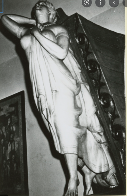
'Good observations on the figurehead, to be sure. A photo nearly from the front in the India House shows the left foot forward concealing the right from that perspective. Yet an image (from p.9 of this log) at nearly the same angle shows the right foot 'crossed' behind the left. This image appears to be an artists impression as explained below. A picture of the India House figurehead from a lower point of view and a different side angle - the point of view of persons walking up the stairs of the India House (and likely the artist) - gives the illusion of the 'crossed' foot ... when it is in reality well behind. Ergo the artist put that into the painting as he saw it from below, yet he also wanted to portray the body from a higher perspective. Arguably, one can see differences in the drapery on the left leg between the India House figurehead and photos of the figurehead on the Glory late in her career. Yet there is convincing provenance that they are both one in the same ... with significant restoration and rehabilitation lovingly done between the time she was at the prow of the Glory and her installation in the India House. We know that the Glory was McKay'slast clipper ... and his masterpiece. We know of her career as well. Documentation held by Hyland Granby Antiques (the present owner since 2021 - Lord knows what they had to pay to get this masterpiece) show that James A. Farrell, president of U.S. Steel in 1923, bought the figurehead prior to the ship's destruction that year. Farrell was one of the founders of the India House, to whom he gave the Glory's figurehead after restoration. Richard C. McKay wrote a preface to a book in 1927 that James Farrell had always been interested in Donald McKay and his ships, especially the Glory of the Seas - which his father, Captain G. Farrell commanded and sailed with young James Farrell around the Horn. Farrell was not just a wealthy collector, but a lover of the Glory from his youth. He was intimately familiar with the ship and desired to save her most beautiful feature - not for himself, but for the public to view and appreciate for what (he thought) would be in perpetuity. Obviously, expert repairs at Farrell's expense were done to reconstruct the missing arm and foot, removing many layers of paint in the process. And it seems most likely that any previous remodeling or repair of the leg drapery in question (perhaps evidenced by blocks or pieces of added wood not original to the sculpture - sometimes found in figureheads or 'cigar store' figures) was corrected in a manner consistent with the exquisite artistry evident in the surviving original work - most of which survived intact. We are lucky that James Farrell was as sentimental and forward-thinking as he was. Johnny EDIT: 'Came across an old newspaper article (too long for everything here) that shed some melancholy light on the subject figurehead (among other aspects of the Glory). 'Brough a tear to my sentimental eye, it did - so I'm adding it here as related by the reporter from the 'old salt' who told the tale. I have no reason to disbelieve it, but if not entirely true - it ought to be. Exerpt from: Transformation of the Clipper "The Glory of the Seas" By Woodbury S. Brintnall (Article appeared in the newspaper: San Francisco Call – vol.110 number 116, 24 Sept. 1911) Of the ships that pass in the night are told many tales passing strange. At night, when outgoing waters of an ebbing tide pull on straining hawsers, you may listen to this—the story of a once proud and mighty ship. You may come to know of the sailor, John Martin, and his sweetheart, long since dead, whose beauty yet lives in the figurehead of the last of the clipper ships, “The Glory of the Seas.” “It looks as though it had a history,” I suggested to the old sailorman, as an opening wedge. “It has,” said he. “Her name was Elizabeth—Elizabeth le Forgue,” he said, “and I guess that even she don't care—any more. There's a bit of a story about that figurehead, too. It was done from life. But lord, even the man who carved it, he's been dead years." "When the Glory of the Seas was launched she was, folks said, the most likely lookin' girl in East Boston. You see, she was to marry him, John Martin, when he come back from the ship's first voyage ’round the Horn to ’Frisco in ’69. He was a likely lad—a little wild, perhaps, and he didn't go back so soon as promised. There was people said she did it a purpose, and some said it was an accident, but, anyways, she was drowned off one of her father's fishing boats, and when the sea gave up its dead—one of her arms was gone.” The moon shone down on the figure of “Elizabeth”—Elizabeth le Forgue. She had but one arm! “And this figurehead,” I exclaimed. “I'm telling you,” answered he, “it's curious like, but the day the girl was drowned the sea was running strong, and when it cleared, the ship's figurehead had but one arm. Course, sailormen are superstitious—but they've never fitted one since that has stayed on. Martin, he sailed some voyages after, and the men aboard mostly thought him queer because he was always a working on that figurehead, beautifying Elizabeth. Sort of duty it was, with him, I guess. He was lost overboard in the eighties in a storm— and ever since she's had but one arm. The company, they don't care—it's knives and grinders now, and salmon and dollars. And tomorrow we'll leave, and pretty soon we'll smell to the high heavens of salmon. I guess ‘Elizabeth’ don't much care. Good night.”


- 3,560 replies
-
- 3
-
-
- clipper
- hull model
- (and 2 more)

