
HOLIDAY DONATION DRIVE - SUPPORT MSW - DO YOUR PART TO KEEP THIS GREAT FORUM GOING! (Only 13 donations so far - C'mon guys!)
×


Dan Vadas
-
Posts
3,261 -
Joined
-
Last visited
Content Type
Profiles
Forums
Gallery
Events
Everything posted by Dan Vadas
-
Pretty good job Clare . Good to see that you're using Chris' Tutorial, he'll do all the "legwork" for you . I guess you've been checking out my IJN Amatsukaze build, so you might get a few tips from my build log. Personally, I wouldn't use Tabs (as a part of the skin etc) for anything. Separate ones (as you're doing) work far better, as they don't tend to spring back. Most places I've needed to use a tab I glue a piece of 0.5mm card to the side of, say, a bulkhead to give more of a gluing surface. Allowances do of course have to be made for the thickness of the paper when aligning it in an inside corner. I also angle most corner by 45 degrees to leave a knife-edge join (with varying success, I'm slowly getting better at it ). I'm also using Testors Plastic Filler on the odd occasion where I do get a slight gap. It dries really quickly, so I thin it with Acetone as I'm using it. To finish it i first cut off any large excess with a scalpel, then use a Q-tip dipped in Acetone for the final finish. The putty finishes really well, and can also be easily sanded. I tried a tube of a similar putty made by Tamiya, but found it very difficult to work with. I'm using Watercolour paint for touch-ups. Have a look at Amatsukaze in another day or so when I finish the handrails on the three Gun Turrets. I'd bought some PE railings for this, but none of the holes aligned with the printed locations (something I've found on both my card models so far) so I'm using 0.2mm brass rod for them. This works really well, as I can place the "stanchions" exactly where I need them. Danny
- 106 replies
-
- 3
-

-
- digital navy
- v108
- (and 3 more)
-
Absolutely wonderful Grant, you can feel really chuffed about the final product . Are you going to enter her in the Canberra Model Show this year? I'm tipping "Best in Show" . Danny
- 339 replies
-
- 6
-
-
- dumas
- Chris-Craft
- (and 3 more)
-
Nice work Slog. I find these type of assemblies are the most fun to build on the whole model. Enjoy. Danny
- 244 replies
-
- 3
-
-
- borodino
- dom bumagi
- (and 1 more)
-
No worries Graham. If you think Amatsukaze is something wait until you see my next model of Bismarck - it's about five times as complex. I said it before and I'll say it again - you've got the talent to make a great model. Your preparations are meticulous . Danny
-
I've done it for you. For future reference, go to the very FIRST post in the thread. Click on the Edit button, there is a Title box in the Editor which you can change/add to. Great start Graham. From what I've seen so far you really have the knowledge and skills to finish up with a superb model. Keep up the good work . Danny
-
Welcome to MSW Piotr. Click on THIS LINK to go to the Group Build of the full model of HMS Triton. Good luck. Danny
-
And thank you John and Carl. You'd be surprised how much weight you need sometimes to keep a join tight, especially on very small parts. Danny
- 295 replies
-
- 5
-
-
- amatsukaze
- halinski
- (and 2 more)
-
Thanks Ken, I had an idea it was something like that . They didn't have those on 18th century ships . Thanks Greg. Danny
- 295 replies
-
- 6
-
-
- amatsukaze
- halinski
- (and 2 more)
-
Also, the higher the deck the more roundup it has. You can see it in this post from my HMS Vulture Cross-section (4th pic down) Danny
-
.... continued. I CA glued tubing together to make the cowl for a small pipe, and also used it for the braces : Not sure what this assembly is (nothing unusual there ) : Quite a few small ventilators, the reel and a viewfinder : An overview of all the fittings glued to the superstructure. I've also fitted the PE railings and 0.2mm wire handrails : Final assembly for this section is the aft Mast, all CA glued together. At the moment it's dry-fitted, I'll spray paint it before final fitting : Danny
.thumb.JPG.cd49a336ac3ccdf8237ac68aca478d04.JPG)
.thumb.JPG.ac25ffb32baeae1e3d076be8ce031153.JPG)
.thumb.JPG.ae25a263f5fd4e045815e1ee36af4b4b.JPG)
.thumb.JPG.cb2bdac114060693e292863b8e500f73.JPG)
.thumb.JPG.fa12dc07b3b0c3687a8b6f28ba0a3569.JPG)
.thumb.JPG.026bfae51e739bd771d755453414a7d7.JPG)
.thumb.JPG.93c41210d5fc31b152d406aaba68199a.JPG)
.thumb.JPG.9c8a4bb7da175520d973ca51d62eccdd.JPG)
.thumb.JPG.5d0f21a9c30b1657a449a876b06653a6.JPG)
.thumb.JPG.c93a571284155f0fc76ae39284d0eb4b.JPG)
- 295 replies
-
- 21
-
-
- amatsukaze
- halinski
- (and 2 more)
-
Thanks Greg and Popeye. Lots of updating to do. This is part of the second aft superstructure, some tricky bends : The start of fitting out the sub-assembly begins with a small structure with a curved roof : Next is a (comparatively) large ventilator. I used a "modified" clamp to hold the tube while the glue dried : I can go to great lengths supporting some of the tiny pieces : Another PE Reel. I've finally worked out the right way to build them : Continued in the next post .......
.thumb.JPG.d960aea66bcf5350e0d2487fcf7f31ef.JPG)
.thumb.JPG.cf45d7011edc40327818abb83e0504fe.JPG)
.thumb.JPG.898ffb7f2f0e81d2f2165c172569da1f.JPG)
.thumb.JPG.ecb147bb9758f76a9bbe5411709956fe.JPG)
.thumb.JPG.9a031c35f9887c185f4f91a08579effe.JPG)
.thumb.JPG.928d987849296c8b6fa6c4b448192799.JPG)
.thumb.JPG.0ce1fd692c51d794ac3720e9ac54625b.JPG)
.thumb.JPG.6edce7fed1aaa4e9be6e4ffce5107f83.JPG)
.thumb.JPG.33707cefb08221ee50d02a7b3d99ca0b.JPG)
.thumb.JPG.ac0a36b950bde39c84bddcd48cae8270.JPG)
.thumb.JPG.7d7af715179861324f0b19140a9fbaa2.JPG)
- 295 replies
-
- 11
-
-
- amatsukaze
- halinski
- (and 2 more)
-
Unfortunately Captain Bob passed away before completing his model. He will be missed by all who knew him. Danny
-
G'day Fernando. Have you had a look at the Norfolk Sloop I built a few years ago? The Link to my Build Log is in my signature below. There were a few problems that I found with the kit, the solutions I came up with are in the Log. The Companionway does look big, but if you were to place a scale figure alongside it you would see that it is actually rather tiny - a real squeeze actually using it . Don't forget, this boat was rather small - not much more than a large Ship's Longboat. There are several pictures and/or Links in my Log concerning the Norfolk Sloop Replica built in Tasmania. This kit is based on that replica. You're doing a pretty good job of her so far, keep it up . Danny
-
Only for SOME of them Jeff. Be aware that the side elevation plan is a FLAT projection, and doesn't allow for the curvature of the hull. The foremost and aftmost ports will be further apart than the plan shows. Check that with the deck plan (if there is one) and make adjustments to the positions of the outer ports. The best way to get the heights of the ports correct is to build one gun now and check that it will actually fit into the centre of the port. In most kits that I've done in the past the guns are either too high or too low to fit the ports properly. Don't forget that the ports will have to follow the "sheer of the deck" - if the decks don't coincide you will have to make adjustments to either the ports or the guns. Danny
-
What Dirk said . That's a weird slope on the top deck, or is it just the camera angle? Danny
-
In this scale the best method to do the treenails is the one you're using. Real (bamboo) treenails will be only 0.22mm in diameter, not impossible but damn hard to do and the result wouldn't be any better anyway. BTW - if you want to be really accurate you will need to do about 5 or 6 times as many as you have already done - as I mentioned several posts ago there are a lot more beams in the "real thing" than the kit bulkheads which are only on about every 4th or 5th "real" beam. My 1:48 scale model of the 16-gun Sloop HMS Vulture had about 12,500 0.5mm bamboo treenails in the hull and decks, and it is less than half the size of Victory . I didn't keep track of how long it took me to do them, as I did the majority of them as I was building and not all in one go, but I'd estimate at least 2 weeks if I did them all at once. The choice is up to you. Danny
-
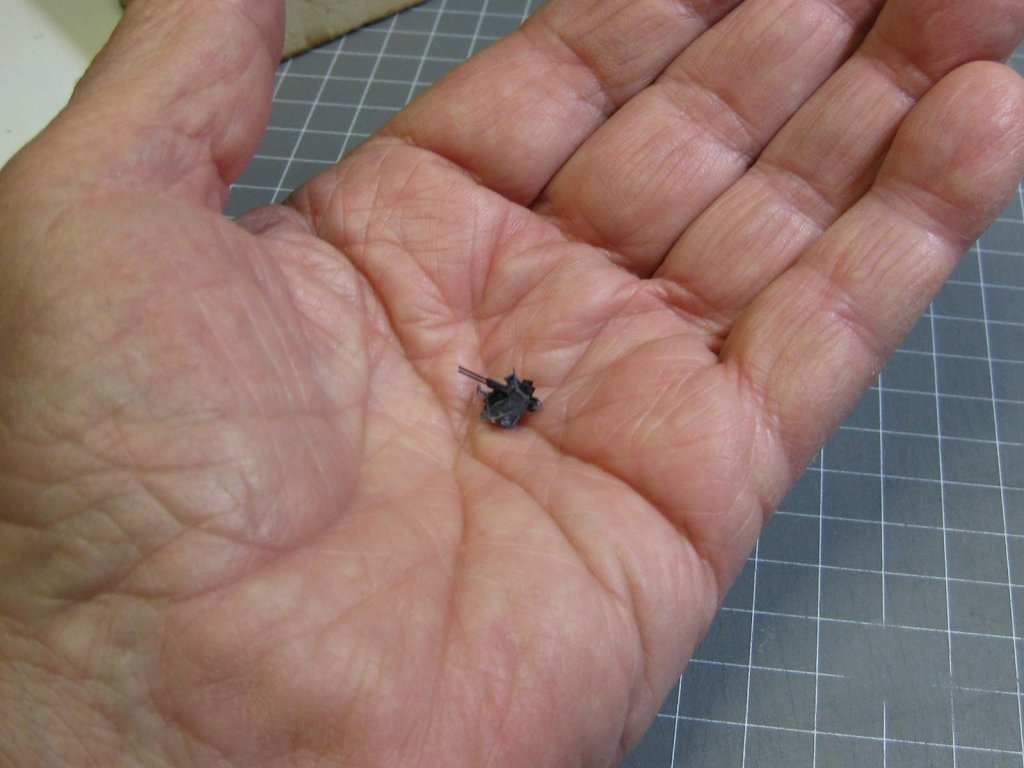
Yep, there are small parts. However, making them from Card is actually easier than from Wood in some cases. I'd have had a bit of trouble making the Anti-Aircraft Guns in the following pics from wood (harder but not impossible ). BTW - they are in 1:200 scale : Danny
.thumb.JPG.9bfb48c7ba9b67d09b07d1d816948a10.JPG)
.thumb.JPG.949883b06c54acd844e1a52a3139475c.JPG)
.thumb.JPG.222f85aec8fb6a3ee39bdb789c21ae58.JPG)
- 19 replies
-
- 10
-
-

-
Don't worry too much about it Toni - the Saddle will cover the whole joint and hide the slight error. The same thing happened on Vulture . Maury, the other two seats are in the aft corners of the head. See HERE. Danny
-
Very nice looking Kits Slog. I see what you mean about "crowding" the parts pages . I also like the look of the plans - I'm not overly fussed about Rendered ones either. I might look at getting a Dom Bumagi kit myself after I finish Bismarck, unless I die of old age first . Looks like you have your work cut out for you for the next couple of years . Danny
-
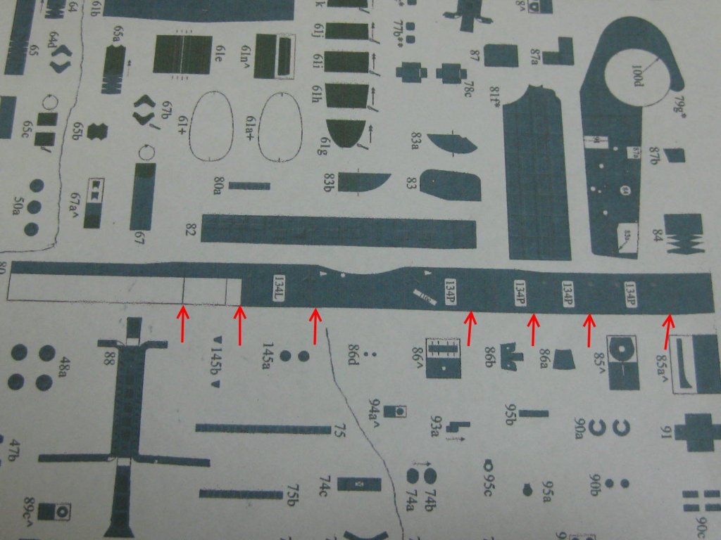
Construction of the Aft Turret Superstructure. For anyone building this model there are a couple of things to look out for. Firstly, the outer wall isn't vertical - it slopes very slightly inward at the top, so care must be taken to fit the framing the right way up. The difference between the length of the tops of the frames and the bottoms is about 1mm or even less and it's easy to fit a frame or two upside-down which will throw the whole side out of whack. Because of the slope the bottom of the side (part #80) isn't a straight cut, even though at first glance it appears to be. I've marked the approximate positions of the changes in direction in the following pic. If the cut is just done straight there will be slight gaps on the bottom of the wall in various places. I added several extra pieces of scrap 0.5mm card to the framing to ensure that the wall didn't buckle when I glued it in : There is a complex curved section which needed pre-forming before gluing : The finished structure before touching up. Virtually no filler will be needed : Danny
.thumb.JPG.ac609ec02076a55aaa43abc81976a413.JPG)
.thumb.JPG.337690b2bba5c75a17caeacb81ad03b7.JPG)
.thumb.JPG.314840eedb22f24a4eb2451cc22d71d0.JPG)
.thumb.JPG.b1a2a080cb30a7fbd89d7f63e5189264.JPG)
.thumb.JPG.aa0d55d76bba9bc49778df80936b2dfa.JPG)
.thumb.JPG.1031c13ab4cde8227bdd9f07ee7b1db5.JPG)
.thumb.JPG.8af5631e8e365cc3fc386ae3a1a5672b.JPG)
.thumb.JPG.27455829035a8eb5719601f4e34542e2.JPG)
.thumb.JPG.1af4f3feb51c57d3b18cd9873b82ded5.JPG)
- 295 replies
-
- 18
-
-
- amatsukaze
- halinski
- (and 2 more)
-
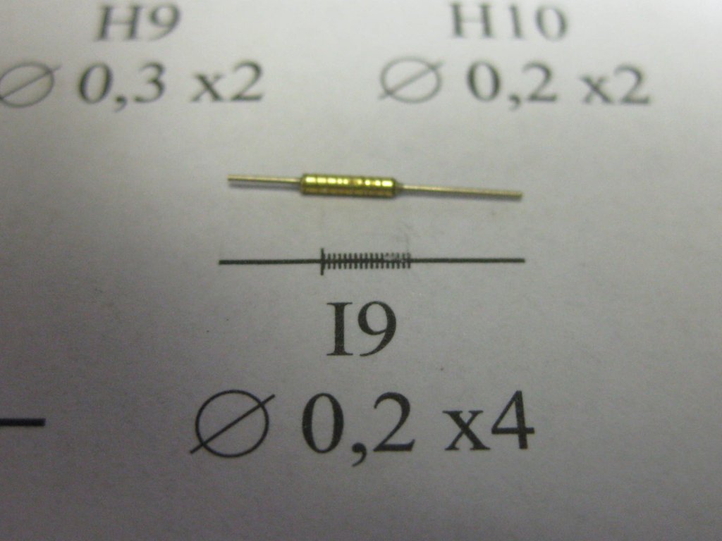
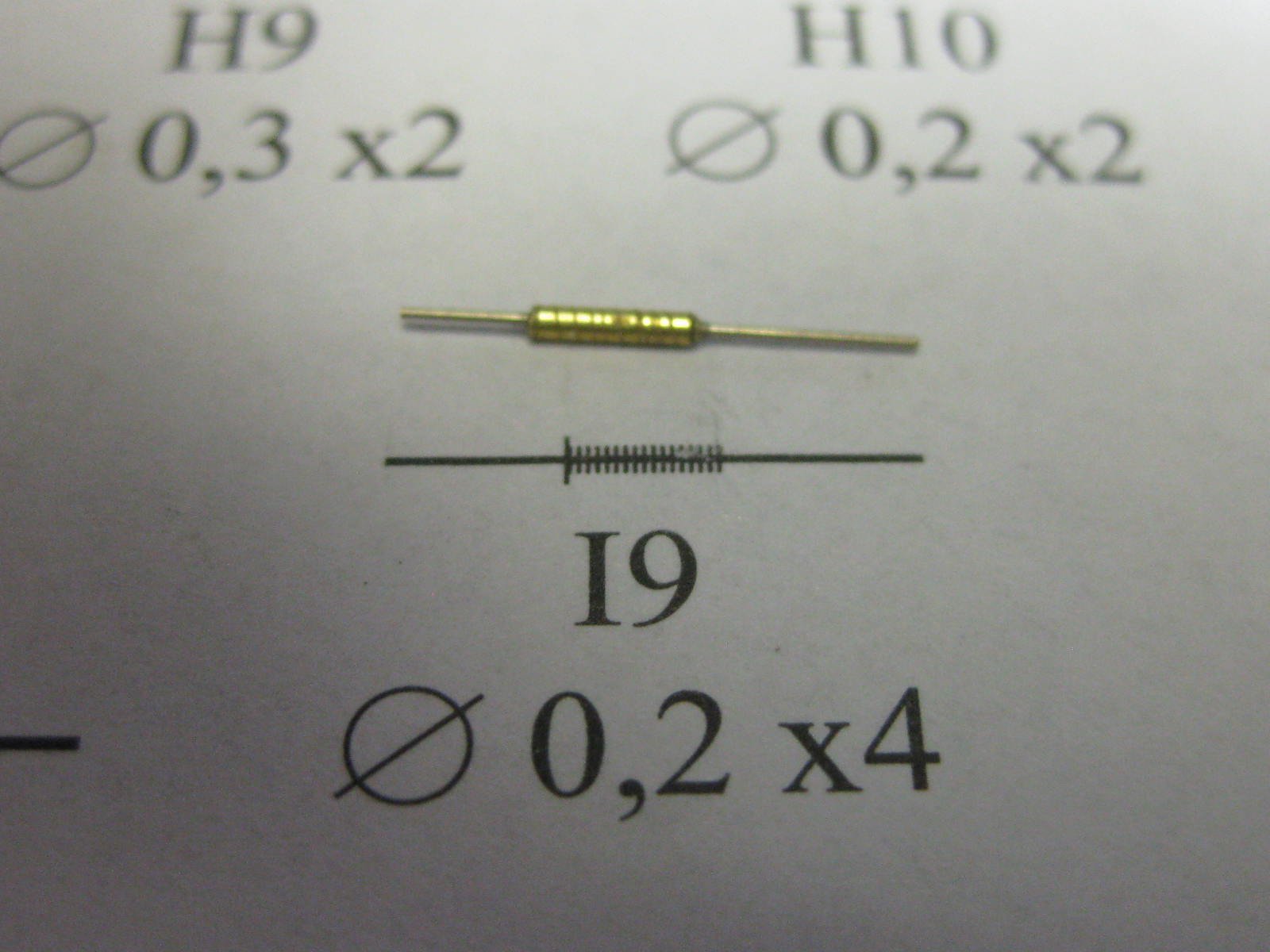
No, just my fingers - it was a lot easier that way. There was quite a bit of waste, but the roll I bought contains .... (I don't know WHAT it contains - a lot ) and tweezers wouldn't grab it. I used them to squeeze it up if I needed to, which was rarely. It really surprised me how easily it rolled around the 0.3mm tubing. My first attempt at these didn't work so well. I used 0.3mm ID brass tubing and tried to score grooves in it to simulate the spring. I'd have run with this if the wire didn't work, but it took quite a while to make one. Here's the failed attempt, above the actual size template - the coiled ones were exactly the same size : Danny
- 295 replies
-
- 10
-
-
- amatsukaze
- halinski
- (and 2 more)
-
Thank you Tom, John and Carl. I don't know about the gauge, but it's 0.2mm diameter. It's supplied by a site that caters for Crafts. Danny
- 295 replies
-
- 4
-
-
- amatsukaze
- halinski
- (and 2 more)
-
Thanks John. Just to blow your mind a bit more : I had to cut the aft funnel back off the superstructure. When I went to fit the AA gun platform to it I realized I'd made an error in the construction of the funnel base - it was the thickness of the base too high . No harm done, just a waste of an hour . A few posts ago I mentioned that the large pipe on the forward end of the aft funnel shouldn't have been fitted until this stage. You can see why below. I've fitted the PE railing around the AA gun platform. It was a little tricky to get all the bends right, and as with the railing I'd fitted previously to the Bridge the stanchions are too widely spaced and don't line up with the marked positions. This makes it look a little odd, as the stanchions are in different positions around the bends. I can live with it though : The railings after straightening and painting : After fitting and painting I noticed that there are two rigging wires that terminate in eyebolts on either side of the platform . I was wondering about the two extra marked holes earlier. I should have checked the rigging plans before fitting the platform to the funnel base, as it made drilling the holes a bit harder. I made the eyebolts from 0.2mm wire in the shape of split pins, drilled 0.45mm holes for them, and CA glued them in : Danny

.thumb.JPG.9bcd1ae636188dea8f389197521341e2.JPG)
.thumb.JPG.82e3abc26ea71f3cf7be68e171c48c5b.JPG)
.thumb.JPG.4b22abd8a0fc82c3fcf31af71ac6bc6c.JPG)
.thumb.JPG.4c6ed85a725e7a7bc61e1defcda70370.JPG)
.thumb.JPG.e943ee280cad19191fba719214f3e953.JPG)
- 295 replies
-
- 24
-
-
- amatsukaze
- halinski
- (and 2 more)
.JPG.ec4a4f11a21bb7e51c34d9d33d2540da.JPG)
.JPG.92cefa5b03bf0b5e65e78c2eb8be9743.JPG)
.JPG.facfe46545f2a2fb67d04889d43693e2.JPG)
.JPG.545033a6ff4b36ffb6504512a8db248c.JPG)
.JPG.1512d2f28379a50f4e89bf5ef1ee9b44.JPG)
.JPG.c87096fa35f3134e2090c93bfe6b1b60.JPG)
.JPG.d14c07f4b644abf2b5d399c3d96c1d98.JPG)
.JPG.542f55ae23f14468143d64001328437f.JPG)
.JPG.665b2d55245d02d98fbea64f40b7cd46.JPG)
.JPG.0ce2d4d7a9baf42228e5d147ae0fafb6.JPG)
.JPG.8388948390f87ec3e189129597654192.JPG)
.JPG.70fa0e0bce7301ee426f4f78e2713635.JPG)
.JPG.904ead04e8c67965c995e2a583106840.JPG)
.JPG.d15bd46ced194af256a248af10148f21.JPG)
.JPG.4ad393b887d51b0e3ed10c10c8cca4a4.JPG)
.JPG.2fe9261f0bd5ae097aca841260e173a3.JPG)
.JPG.74cb877f9f51985a1827560620d7db40.JPG)
.JPG.a56be3c74b2bf4f265dadcaa2b85f2dd.JPG)
.JPG.11eec11fab8c46e05cfd974dbacc73ee.JPG)
.JPG.52ded8a0644f9ceb863fe63a7735e30f.JPG)
.JPG.3a8e08c4a49f71a2336d054c15f8560a.JPG)
.JPG.48c7b5d4012469b499f48452cf442861.JPG)
.JPG.e83515ea5863373e84316ac4d5b30173.JPG)

.JPG.6445bca372c4303b0cdd836795ec9ab5.JPG)
.JPG.55b1cd39e6f96378eaca10569f4a8be1.JPG)
.JPG.3add103c0003dd967c907abaa4e43c6d.JPG)
.JPG.bd2a5c3be78bd522fe9d631a2880b213.JPG)
.JPG.c3db930ac39f828fffcb4e2189952ca3.JPG)
.JPG.c73e8208718e186aa9da46ac2ca05b31.JPG)
.JPG.f476efd803f830d6106b4404bd8d9837.JPG)
.JPG.8d45bebe0dad4354b1631119c6214eae.JPG)
.JPG.166ca1b8c29e415d94c07af6190f7fd8.JPG)
.JPG.e937946366f2102a9f54d8e588e950df.JPG)


.JPG.6c6875f4d87d01b9670720225983cd9b.JPG)
.JPG.54f200b2d62c24bbaf0422c86e56369b.JPG)
.JPG.7215d970ddfe38c46da4d7165ba1f4ab.JPG)
.JPG.633d89d5c48c42216d81e26640e233c7.JPG)
.JPG.df1183c4ee7004b6b5427237f7e6161b.JPG)