
Thukydides
-
Posts
1,369 -
Joined
-
Last visited
Content Type
Profiles
Forums
Gallery
Events
Everything posted by Thukydides
-
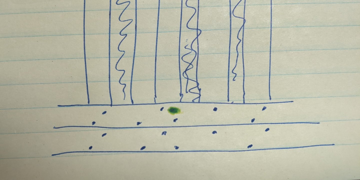
 My interpretation of the statement was that every alternating timber gets a single treenail and the others double treenails. See below I added the number of treenails on each frame as well as a potential arrangement in red. That being said it is possible that the double futtocks were treated as one timber. I think an equally justifiable option would be to have two in each timber as per Ollivier. Ultimately up to you as I don't think there are clear answers here.
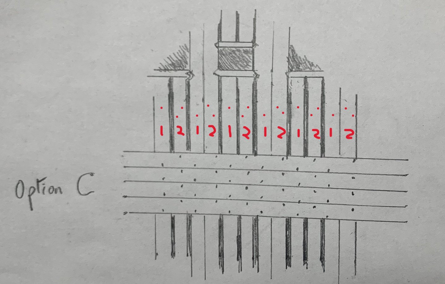
-
If I had to guess I would say that this is referring to the new steppings bracing system that came about around this time. I believe that Steel refers to to this elsewhere in the document. The key point in the quote above is not what they do currently, but what he says they used to do (2 treenails in one frame and 1 in the next).
-
This is what Ollivier had to say in 1737: Note: he previously notes that there were three ships being constructed in the dock at the time he was there, an 80, 70 and 60 guns respectively. I am not sure which two of these he is referring to in this quote.
-
In Steel's naval architecture (1822, so a bit of a later period) there is a section near the end where he describes the process of making ships. https://archive.org/details/elementspractice00stee/page/167/mode/2up On page 37 of this section he says the following: What is interesting is what he has to say after talking about what is done currently. He says that alternating single and double treenails were used. Maybe something like this: I will take a look at my copy of Ollivier when I get home. That dates from 1737, but many of the techniques he describes changed very little over the course of the 18th century. He has a surprising amount of detail and maybe commented on the number of treenails used. I know he did mention the fact that the English used treenails much more than the French, but off the top of my head can't remember what else he said.
-
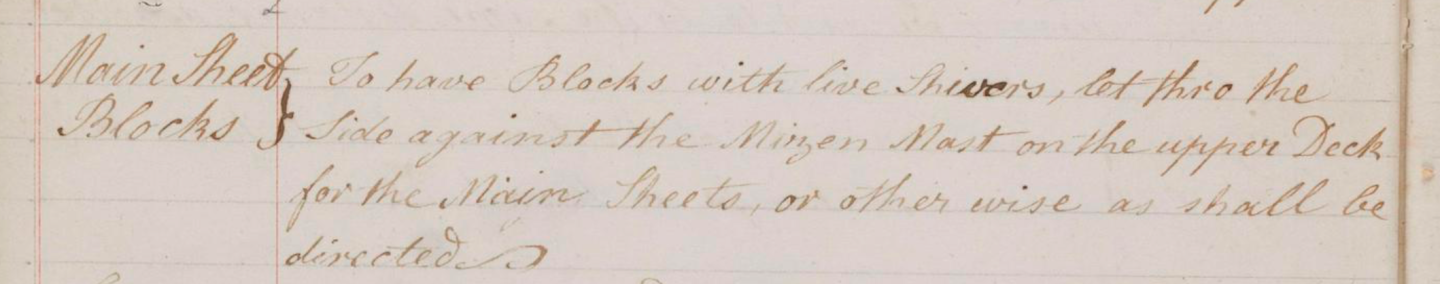
I am wondering if anyone is able to help me in interpreting the following lines in a contract. In particular I am confused as to what “live shivers mean.” I have included both the original text as well as my transcription. Mainsheet Blocks To have blocks with live shivers, let through the side against the mizzen mast on the upper deck for the mizzen sheets, or otherwise as shall be directed.
-
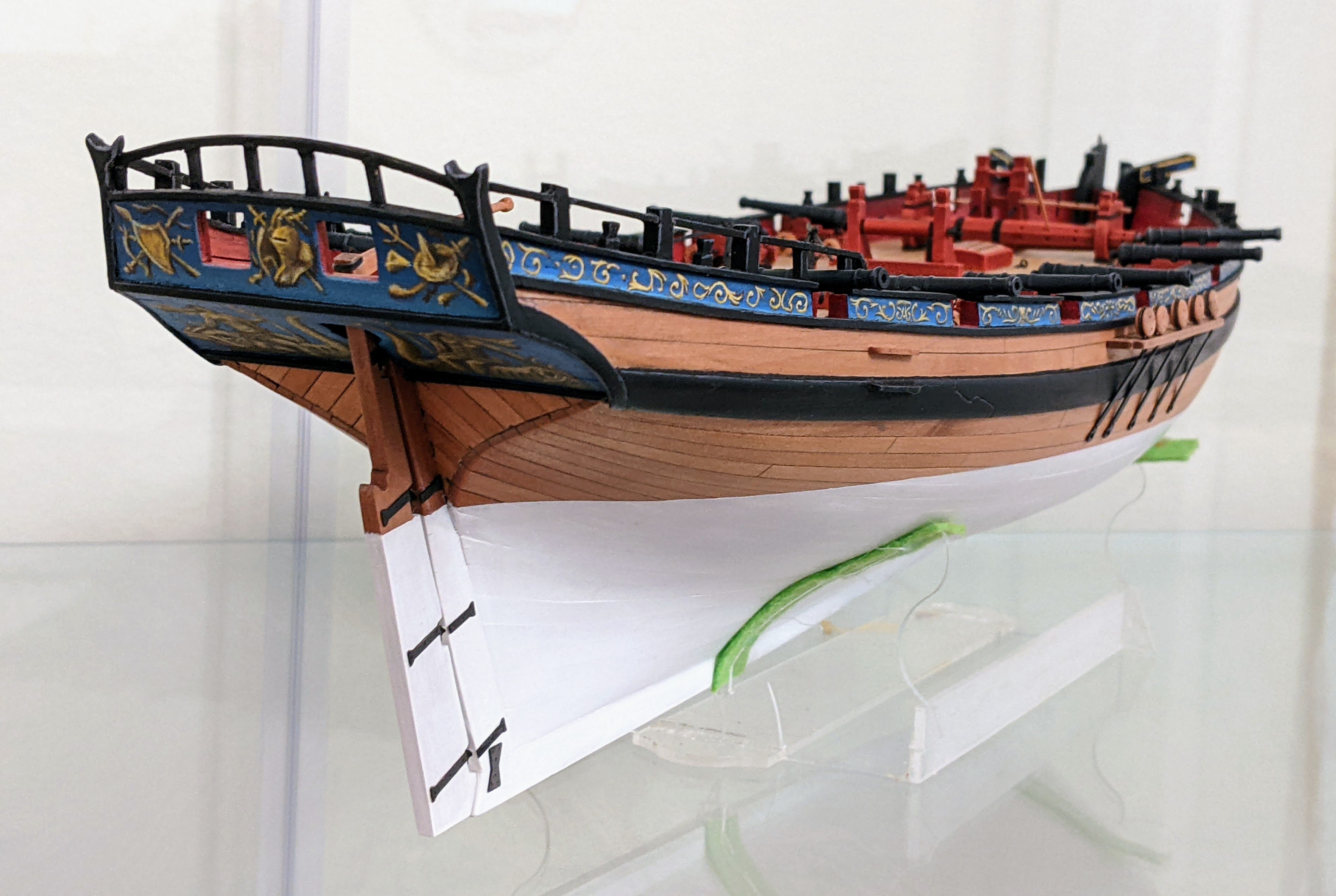
She is a really lovely model. If I wasn’t already committed to another project for the foreseeable future I would be sorely tempted by her.
- 76 replies
-
- 5
-

-
- Harpy
- Vanguard Models
- (and 1 more)
-
I like it. Very nice.
-
It might be the coppering that made Christ move it to a 3, I would trust Chris' rating better than my very uninformed gut feeling :). That being said difficulty is not a one size fits all problem. You may excel at a task I struggle at. Some models have more complex rigging, others harder planking, others tedious copper plates:). So a clear eyed view of your own abilities plus reading lots of build logs is probably the best way to know if you are capable of completing the model.
-
My best advice would be to wait until you are closer to being done. What you want to do next may change and also your assessment of your skill level based on how the rest of your current model progresses. That being said Speedy would probably be the easier of the three examples you gave. Adder's planking at the bow is a bit more difficult and Granado is an older kit so more adjustments / interpreting of the instructions will be required. Read some build logs of your potential choices and then assess if you think you have the skills to do the build. Apart from that is really up to what subject inspires you.
-
Very nice Chris. These are a great addition to your line of boats.
-
methods for serving a thin rope
Thukydides replied to georgeband's topic in Masting, rigging and sails
I did a lot of very fine serving for my Alert build including serving eyes for 0.25mm rope. I used the syren serving machine for all of this. See below for a picture of a served 0.35mm rope used for the anchor buoy. Personally I am of the opinion that as much as possible you should try to replicate the full sized practice. I do notice the difference (not just in zoomed photos). That being said everything is a tradeoff between how much time you are willing to put in and what you are capable (e.g. how good is your eyesight). I detail some of the process in my log, but her are some things I learned: Scale matters - You need to make sure you are serving with an appropriate sized thread. For the above example I was using 10/0 fly tying thread for the serving. Magnification is essential - Without good lighting and some form of magnification (I use 3.5x glasses), it is impossible to be consistent and get a good result. By the time you notice there is a problem you are long past the point at which it occurred. Patience - For small examples such as the above I would say I made twice as many attempts as I got acceptable results. Mistakes happen, measurements on length are 1mm off and at this scale that stuff can make a noticeable difference. Get comfortable with doing things over until they are done right. Twist - Some thread (fly tying thread in particular) needs to have its twist tightened or it lies too flat. As I serve it onto the rope I twist it in the direction of the original twist. This is hard to describe, but when you do it right you can see the individual loops of the serving as opposed to a smooth layer of fibers. This obviously untwists the thread below where I am twisting so when done I just get rid of the fly tying thread I have untwisted. Thread is cheap so this is not really a problem. Knowing how much twist to add just requires practice. Tension - There is no way to show this, but an important part of serving properly is maintaining the correct tension and spacing (no gaps). This is much easier to do with larger ropes and much harder in miniature. This just requires practice. Limit glue use - I found glue at small scales is really noticeable. So as much as possible I would use tricks where I pulled the ends under the serving. This is a bit hard to describe, but essentially I was using the common whipping at both ends of the serve. Problems with securing the two ends of the serve were the most common reasons for having to redo things. EDIT: added a note on glue which I forgot to mention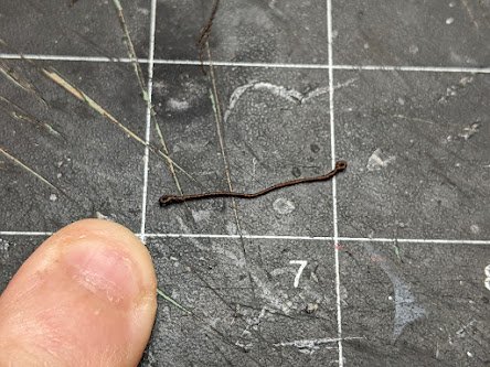
-
Finish sequence
Thukydides replied to shipman's topic in Painting, finishing and weathering products and techniques
I will just add on the acrylic question, if you are using an oil based sealer you can paint acrylic over it, but you probably need to abrade the surface a bit and use some sort of miniature painting primer (e.g. Vallejo) or it will flake off. -
Beginner - Rigging Tools
Thukydides replied to nheather's topic in Modeling tools and Workshop Equipment
Welcome to MSW. The advice everyone else has given you is great and I would heartily endorse it. Tweezers, sheers and maybe a small sewing needle are all you really need for sure. The only addition I would make is some sort of serving machine if you plan to serve some of the lines (e.g. the syren one). I will just add a few things that I learned rigging my first model: The hull will take a while so there will be plenty of time to consider the rigging as you get closer to it. I changed my mind so much on things over the course of the build that I think it is best to wait till you are much closer to actually doing the task before purchasing things. In general I have found a good rule of thumb is not to buy a tool until I have a task I am working on that I need it for. Don't buy tools to solve hypothetical problems. Everyone goes about rigging a little differently. There are lots of tips and tricks you can pick up from others, but some of the tools are a function of what you are trying to do. Fore example, I was doing a lot of false splicing and so created a small hand tool using machine sewing needles to help me do this. For me it was one of my most used tools for rigging (along with the serving machine), but if you are not interested in doing that sort of detail then it would be useless to you. -
As others have said I would guess the tops as they could easily be replaced and thus the barrels reused. There are lots of references in the captains logs I have been reading to empty barrels being returned to the victualling ship. In terms of what was on the label again I can only speculate, but there are some clues in the logs. Take for example the following entry: It appears to me that captains were held responsible for the amount of stores they consumed as a significant portion of the logs are spent detailing what was opened when and how much it contained. From the above example we can see that here was likely some sort of reference number on the barrel (in this case N 212). I assume N refers to No or Number, but it is not clear if the N would have been included or just the number. Also it seems likely to me that there was some indication of much the barrel contained (in this case pork). The reason I suspect this is pretty much every time a food barrel was opened, he details how much was in it. I have tonnes of examples like these I could show you if you wanted to see them. In summary I would say if the barrel in question contained food, I would expect a label on the lid with a number (e.g. N212), the product in question (e.g. salt pork), and the amount of the product contained within. One final note is that it only seems to be the meat that was catalogued in such detail. The logs are much more vague with regard to other commodities being consumed though they do carefully not the number and types of barrels brought on board.
-
That is rough Alan, I feel your pain. That being said I bet the decks will look much better now you have learned all the mistakes the first go round.
-
Ratline thread recommendations 1/75 scale
Thukydides replied to John AA's topic in Masting, rigging and sails
Some of the fly tying thread is polyester, just much thinner than any guterman thread. I used it for serving smaller lines as any other thread was oversized. Probably overkill in the case of ratlines as you can get a properly scaled guterman thread, but for the seizing you need something smaller. -
So Cheerful was launched in 1806, so I don’t have a clear answer for you, but here is what W E May recounts (based on Admiralty documents): 1779: Cutters and Brigs to have a 4 oared yawl or cutter 1783: Cutters to have two boats instead of one (not clear what the second would be, potentially a yawl and a cutter?) 1815: Cutters to have a 20ft deal cutter. It is also mentioned that new cutters (those of 200 and 193 tonnes) should have a 22ft gig and 16ft cutter.
- 11 replies
-
- 2
-
-
- cutter
- ships boats
- (and 1 more)
-
Oh I didn't forget about her 😀. I just didn't bother to mention it as she is not really a contemporary example in my view. The problem is Victory has been rebuilt so many times over the years that much of her current appearance is not really reflective of what she originally looked like. @Morgan I believe is working on a book which will discuss some of the many changes to victory so maybe he might have more to say. However, my understanding is that the head was rebuilt at the very least on the early 1900s (there are some diagrams in Bugler's book about the restoration). However to my knowledge there is no reason to believe that even what was done then reflects her original appearance. I did consider adding a discussion on victory to the writeup, but though I am reasonably confident that the modern victory is not a reliable source for how the original head was constructed, I didn't feel I had enough useful things to say and so decided not to mention her at all. As always I do appreciate that you took the time to engage and suggest things I may not have thought of so please don't take this as me dismissing your suggestion. If you have come across any evidence to suggest that the modern head of victory does reflect 18th century practice I would be happy to be shown to be wrong 😀.
-
Vanguard Alert - Rigging problem
Thukydides replied to rodricbraithwaiteRodric's topic in Masting, rigging and sails
I am glad you found my log helpful, I am sorry I never noticed your original question till now or I would have responded. Yes this is an inherent problem with Alert. Goodwin is often not reliable and if I had my time back I would have thought more critically about his assertions. You are correct in saying almost all of the cutter examples you can find use the tresstree to attach the shrouds. However, on the other hand almost all of the models are from a little later than Alert. My gut is I would have gone with Hawke as it is contemporary and about the right size (Alert was a larger cutter) and period, though I have not given it a ton of thought as it is too late for me to change anything now. I have also since found a possible rigging warrent for alert which might help. https://www.rmg.co.uk/collections/objects/rmgc-object-557865 One of the key things to remember is if you run the shrouds up to the trestle trees, you need to reverse the topgallant mast (so the topgallant is in front of the mainmast). I would also recommend you check out Blue Ensign's log as I relied on him heavily and he goes into great detail regarding his thinking on matters such as this. I would also note in my case that I did a few things wrong (in retrospect) with regards to this area of the model: I confused the pendants of the tackles with the running backstay tackles. So I missed the pendants of the tackles which should hang below the shrouds. BE correctly shows this in his build. I followed Goodwins arrangement for the shrouds which I am pretty sure is wrong. It should have been the last shroud that was a single instead of the first. -
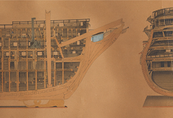
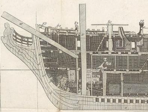
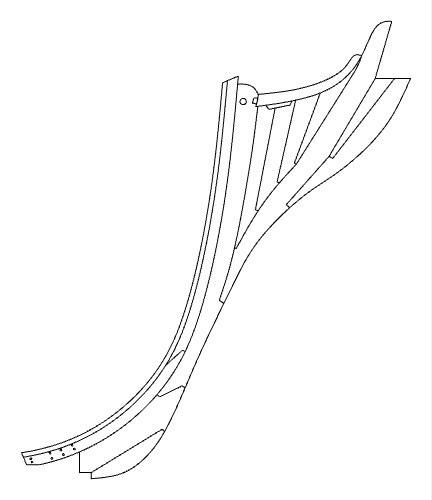
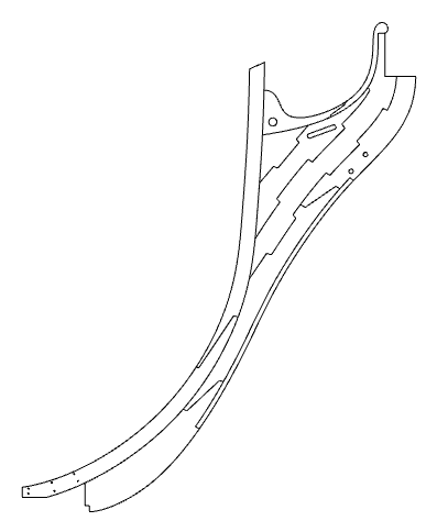
Log #11: Researching the Knee of the Head Part II I am finally starting to lock down the design for the structure of the model and an important part of that is the knee of the head. As promised here is the second part in which I cover the remaining historical examples I was able to find as well as my preliminary plan for what I will do with Perseus. We left last time with the example of the Bellona model and after the it, there are no more significant depictions of English knees of the head until the early 1800s. However, an interesting example of French construction from the late 18th century can be found in the Encyclopedie Methodique: Marine by Vial du Clairbois. Sectional Profile of a French Frigate, Circa 1783 Vial Du Clairbois, Encyclopédie méthodique, Plate 82, archive.org. The illustration shows the inboard profile of an unknown French frigate. The head is composed of many timbers, of a common curve, scarfed into one another. Clairbois’ commentary notes that this is a significantly more economical way of constructing the head and he further notes that the method is more like English or foreign practice as opposed to French. The upper part of the knee of the head bears a striking resemblance to the Ollivier drawing and it is notable that this example differs considerably from two other examples of French knees of the head depicted in the volume. Steel’s 1812 book on naval architecture includes no detailed diagrams showing the knee of the head, but does briefly describe the process by which it was constructed: Though this does not assist in describing exactly how the head would have looked, it does reinforce the idea that shipwrights tended to have broad latitude in how they constructed the head and the specific makeup likely depended on the available timbers. The description of the methodology is also reminiscent of Ollivier’s description of how English shipwrights he observed constructed the head. At some point in the early 1800s the design of the knee of the head appears to have begun to change. The new designs featured a timber called the stem piece which runs parallel to the stem all the way to the top of the knee of the head replacing the standard. The lacing then buts against this piece with the chock pieces made up of a number of wedges filling in the remaining space. These changes can be seen in a sectional plan of HMS Nelson, a 1st rate launched in 1814 showing the arrangement for the knee of the head. Sectional Plan of HMS Nelson 1814 National Maritime Museum, Greenwich, London. PAH9223. Once again we can also see that each of these components of the head was made up of many different pieces scarfed together. The figurehead is also much smaller in keeping with 19th century practice depicting the figure from the waste up. This shift in practice for the construction of the head is also evident in John Fincham’s 1821 book on the practice of shipbuilding. In it, there is an illustration which, similar to the Nelson 1814 example, shows a stem piece running from alongside the stem. In this example, the stem piece continues down to lock into the gripe. The diagram also shows the separation of the gripe into two pieces which Fincham explains is to allow this piece to separate in the event that the ship is grounded to avoid the entire gripe being carried away along with the false keel. Fincham’s diagram also includes a horseshoe plate to secure the gripe to the stem. The Structure of the Head, Circa 1821 Fincham, Outline of Shipbuilding, Plate 4; Lavery, Nelson’s Navy, 63; redrawn. Like Steel, Fincham’s description of the construction of the knee of the head makes clear that shipwrights had broad latitude in how it was constructed. Having considered the available contemporary examples of the construction of the knee of the head we are left with more questions than answers. Despite this there are probably a number of key conclusions we can make about English construction of the knee of the head: English construction practices for the knee of the head likely varied from shipyard to shipyard and based on the available timber. Individual parts such as the lacing, chock etc.. were likely made of multiple pieces of wood running parallel to each other or following a common curve. The individual pieces that make up the head were at times scarphed together. This may have been the standard practice, but there is insufficient evidence to definitively make this assertion. The following is a potential arrangement of the knee of the head consistent with the historical examples reviewed. It should be noted that this is by no means the only reasonable way one could speculate Perseus’ head was constructed, but is meant to illustrate one possible arrangement. It incorporates the shape from the draught, the available dimensions in the contract and broadly follows the Bellona model. I am a little apprehensive about if I will be able to pull it off. Getting tight joints with those scarphs may be hard. However, if I find I can't do it, I may pivot to simply copying the Bellona arrangement.
-
Ratline thread recommendations 1/75 scale
Thukydides replied to John AA's topic in Masting, rigging and sails
I used 0.2mm rope from ropes of scale. Ben was able to custom make some for me and it turned out great. This was the correct scale for my 1:64 scale cutter. It is more expensive than just buying thread, but you get much nicer definition. -
As Chris said really it is up to you. The reality is that the state of a deck would have changed significantly depending on the circumstances (are they cleared for action or just sailing along). So you have essentially two choices: Pick the exact scenario you are trying to depict and do so accurately (e.g. show the tackles laid out if the ship was ready for action or shut the ports and secure the cannons to the side of the bulwarks if just sailing along). Do some sort of representative scenario (this is what most people are trying to do). Essentially you are depicting some of the many things that were done on the ship even though it is technically inaccurate to have them happening simultaneously. But in this case it comes down to what you want to depict and how aesthetically you want to present it (a ship model is a work of art after all). Though with #1 there might be a technical right answer there is most definitely no right answer to number two as it depends on what YOU are trying to depict. TLDR: do what you want
- 4 replies
-
- 10
-
-
Fantastic work Glenn. She really is exquisite. I have enjoyed following along watching her take shape.
- 840 replies
-
- 3
-
-
- winchelsea
- Syren Ship Model Company
- (and 1 more)


