allanyed
-
Posts
8,149 -
Joined
-
Last visited
Content Type
Profiles
Forums
Gallery
Events
Everything posted by allanyed
-

From out of the shadows ...my first post!
allanyed replied to RobTBay's topic in New member Introductions
Rob, Welcome!!!! "Kit bashing" is a great idea with some kits to take the model to the next level, especially the planking, replacing the gratings, and replacing the bowling pins provided with belaying pins in some cases. You might consider taking a little time to study the planking tutorial by David Antscherl here in the MSW gallery and the YouTube videos by Chuck Passaro It takes time, but there is SOOOOO much information right here in the MSW build logs to study that will help you. Study the scratch builds as well as the kit builds to get a better idea of what can be done. Allan -
I second the motion. Every newbie would be well served to start with this three vessel series. Not only will it give you useful experience in the build, but will teach you what to watch for in future kits if you go the kit route or even help you with scratch building techniques if you choose to join the many members hanging out on the dark side. Welcome to this motley crew. Allan
-
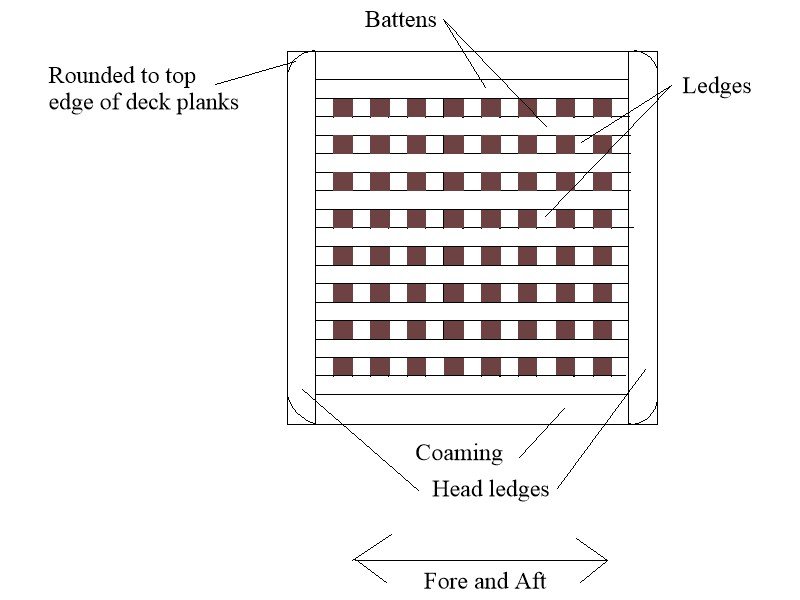
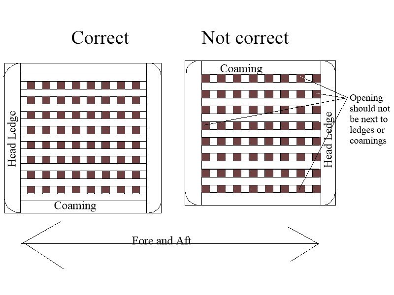
Your version is a huge improvement with the brackets not being plywood. Are you going to add the breeching loops which were used on Blomefield pattern guns which came into use about 1787, including on the Artois class ships such as Diana? Small note for the future.... your gratings look good as they have no openings next to the head ledges and coamings, but the battens on the gratings ran fore and aft rather than athwartships. Allan
-
Never having been in even one, let alone all, grand lodges could you please help me understand how this relates to ship models? Many thanks. Allan
- 106 replies
-
- 1
-

-
- Admirals Barge
- Vanguard Models
- (and 1 more)
-
I may not be understanding this clearly but with all the silicone molding materials that require only a single pour, this seems complex. For small parts I make a master of wood or modeling clay. I then pour an ounce or two of mixed two part silicone molding material into a small paper or plastic cup. The master is then set into the liquid silicone so that it is completely submerged but with the top surface of the master just barely exposed. Once the silicone is cured, the master is popped out and the mold removed from the cup. For small parts such as wreaths there is no need for a stiffener for the mold. The mold can then be used to make parts using casting resin which only takes a few minutes to mix, pour, cure and remove from the mold. Allan
-
Glenn brings up an important point. Sapelli or the "walnut" found in some kit boxes are not appropriate woods for ship models in most cases. It is porous with a lot of visible grain and often brittle thus difficult to work. A tight grain should be a major consideration. Consider buying a good quality wood and replace the sapelli. Boxwood, Alaskan cedar, basswood, Swiss pear, and other species folks here can recommend. Dry bending works, but there is nothing wrong with soaking a strip before shaping as it often makes it easier to shape plank around the bending piece as seen in post 7. Both methods have worked well for many members. Allan
-
I respectfully disagree. There will be problems as the bulkheads are not marked out for the proper width of the planks. The width of the strakes is dynamic from stem to stern but these appear to be the same width their entire length. Bob, I realize most kits do not show proper planking techniques but if you have not already done so, study the videos by Chuck Passaro on how to plank a hull. It will help to wind up with a high quality realistic planking of your hull. Allan
-
Welcome to MSW!!! Not sure what series Dave is referencing, but there is one that others have tried and have great things to say. https://modelexpo-online.com/Model-Shipways-Shipwright-3-Kit-Combo-Series_p_5465.html Hopefully you can find these from some other supplier that is not so far away from you.
-
No matter how you do the hold down, pins or clamps I have found that the best way to go about the heating process (at least for me) is to use a heat gun. A hair dryer will work, but it was frowned upon by the admiral when I did that. An industrial heat gun is easily adjustable plus had higher temperature limits and was cheaper than a hair dryer. It is sometimes hard to maneuver a heating iron around the clamps and pins where as the gun gets heat to all points. Allan
-
Hi Highlanderburial It appears you did not mark out the plank widths at each bulkhead which may be part of the problem. The width of the plank is dynamic as it goes from the stem to the stern. If you have not already done so maybe consider studying David Antscherl's planking writeup here in the MSW Articles archive and Chuck Passaro's videos on planking and you will have an easier time of it on the next planking job. Allan
-
If you need to use the pre-cut strips, you can probably succeed using Chuck's method instead of what you show in your photo. What you show does not follow his method. After lining out the bulkheads and subsequently tapering the width of the plank follow part three where you can see that there is a hold down for the plank so it does not ride up and a former piece with the curve that is needed. Allan )
-
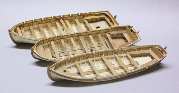
Hi Ross! What scale? Plank on frame might be a bit difficult at 1:85 if that is the appropriate scale, but certainly can be done. As the boats were stowed right side up do you want the interiors to look realistic, including having all the pieces to scale? I have had the most success using a method similar to what Frolich describes in his book Art of Ship Modeling. It is also described in detail in volume II of HMS Euryalus. You can also try a method similar to that used by several kit makers including the Medway long boat by Syren. A 38 gun frigate of 1794 would probably have had five or six boats including a 24 foot launch, a 30 foot pinnace, a 24 foot cutter and 18 foot cutter plus two smaller boats based in information from May's The Boats of Men of War.. It sometimes varied from ship to ship based on the preference of the captain. For a model, most folks would only include 2 to 4 boats. You can find great information, including scantlings for each boat in the W.E. May book. Below are a 1:48 scale cutter, pinnace, and launch built using the methods detailed in the Euryalus book. Allan
- 12 replies
-
- 3
-
-
- Frigate Diana
- occre
- (and 1 more)
-
I agree totally. If you have misunderstood it based on the RMG description, you are certainly not alone!!😁😁 RMG is run by people so as with all of us, mistakes happen, including the written descriptions. This would not be the first I have seen. This may be the case here as there is one man per thwart rowing so would be considered single banked by any definition I have ever seen. I just did another quick definition search and every one that I read states a variation of the following A boat that is "double banked" has two crew members sitting on each thwart, each pulling an oar on their side of the boat. In a "single banked" boat, there is one person on each thwart pulling one oar. There is no mention anywhere of empty thwarts between rowers. With a breadth of about 6 feet, there is not enough room for two rowers on one thwart. There has been a lot of discussion and sketches here at MSW lately regarding the minimum breadth for a double banked boat and the consensus is that it would be at least 6 feet 9 inches and more likely wider. Allan
- 106 replies
-
- 3
-
-
- Admirals Barge
- Vanguard Models
- (and 1 more)
-
BE She looks like a really nice boat!! Is she single banked or double banked, hard to tell from the photos on the box. It seems to have twelve thwarts but 6 tholes per side so I assume single banked. By the same token from the photo it looks like there are six pairs of tholes lined up for the same thwart so every other thwart is not being used. At 1:64 scale and 29mm breadth that is only about 6 feet so it leads me to believe single banked like the following RMG model and plans.
- 106 replies
-
- 5
-
-
- Admirals Barge
- Vanguard Models
- (and 1 more)
-
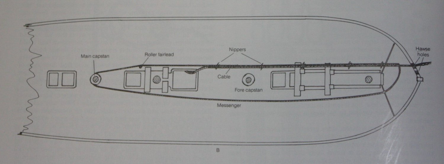
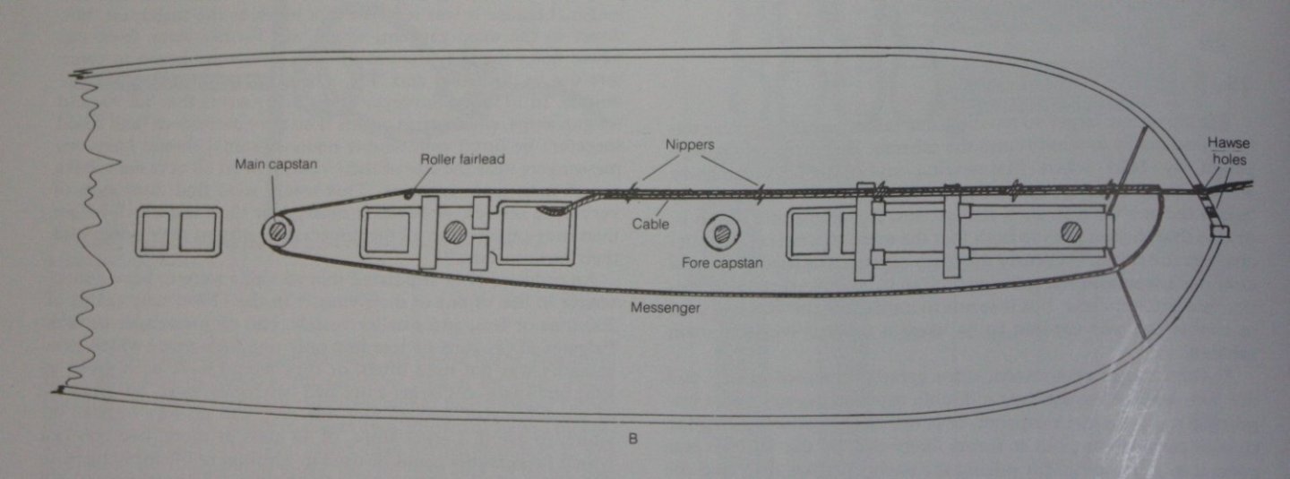
I think BE has it spot on once the messenger would have been removed. The following is from Lavery's Arming and Fitting English Ships of War (ISBN 0 85177 451 2) page 48. Allan
-
The frames look pretty close as far as sizing. Can't tell from the photos, but per Mays' scantlings for a 16 foot cutter, 7/8" X 7/8" at the heads is what he shows. As to the room and space, that brings up a great point. Lacking other information, I generally use the station lines as the locations for the frames. If anyone has more accurate contemporary information on room and space that would be fantastic. Your dimensions for the frames and spacing looks close, and superior to the framing on ships' boats found elsewhere. Allan
-
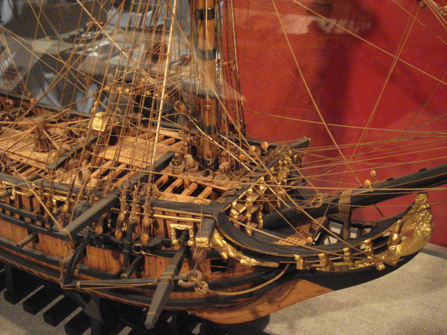
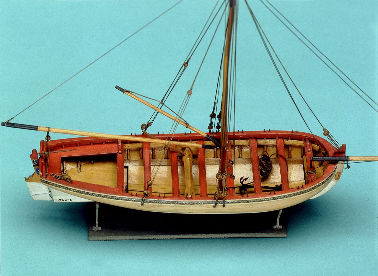
WELL DONE! The last photo brings up something that is not always seen on models with the proper size and number of frames. The thwarts and benches both are notched to accommodate the frames which follows the detail seen in the contemporary model in the photo below. Thanks Allan
-
This is absolutely fantastic Chuck. It is so nice to see a properly designed knee of the head with the multi direction tapers. Allan
-
Further to Druxey's post, the following photo of a model at Preble Hall may help. Allan

-
I looked up reviews of Super phatic glue and most are good, but with a cautionary tale from several users including this one. I've used Super Phatic glue for the last 3 years after I developed an allergy to CA. I penetrates balsa pretty well and holds better than any other glue I've tried and it dries pretty quickly. I have only two issues with this stuff. 1. After it dries, it remains very slightly flexible which is good for strength, but it means it can't easily be sanded smooth. So keep it off the external side of wing or fuselage panel joints. 2. If stored for more than a few months without having been shaken, the glue separates in the bottle and can't be re-mixed. I bought 2 bottles at Toledo (from the Deluxe Rep) last year. Used one immediately, the other (from the same box) sat on the self for 10 months, when I finished the first, I grabbed the second and it was a solid chunk. I also just received a "new" bottle via Amazon that had hardened - I suspect it sat in a warehouse too long. So keep it moving. Otherwise, Great Stuff! Do the channels have standards on top or hanging knees or similar supports on the underside? Either of these should give a lot of support sans the use of pins which are a challenge to align in the hull and channel. I have used pins, but the only way that seemed to work for me was to insert pins in the channel first with a tiny protrusion. The next step was to mark the hull with these pins points and then drill the receiving holes. Last was to remove the first pins in the channel and replace them with pins that were long enough to penetrate the hull planking. I used bamboo rather than metal for the pins so I could use PVA rather than CA or epoxy. Allan
-
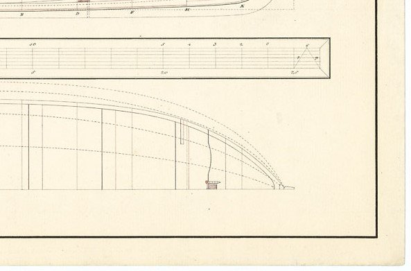
Craig, ZAZ7028 shows something similar, but with the notch for the mast on the aft side of the cross piece. This would make it easier to raise and step the mast rather than having to lift it and lower through the holes. Note that the mortise is square. I am guessing this would have the mast square rather than round from the point where it rests in the mortise down to the step. The plan also shows what appears to be the securing device. Allan
-
HMS Terror by Rking - OcCre - 1:75
allanyed replied to Rking's topic in - Kit build logs for subjects built from 1801 - 1850
Your workmanship looks grand. I am not sure about this particular ship but based on contemporary information other RN ships' gratings as well as the head ledge and coaming assembly have round up. It is often a smaller radius than the round up of the deck. Also note that the grating does not have openings against the head ledges or coamings. The sketches below may describe this better than words. The openings were smaller than 3" square, about 0.04 at your scale. Allan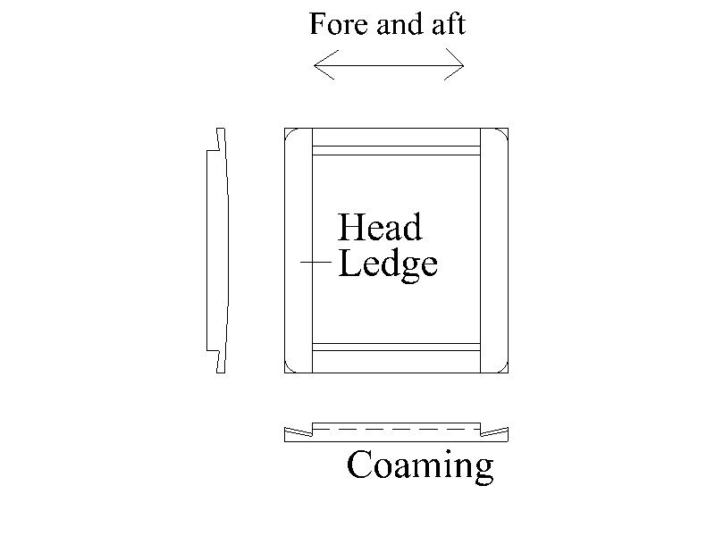
-
Welcome from a former NJ ship modeler. I also highly recommend you visit the club as suggested above, they are truly great group with tons of experience. Allan
-
https://www.thewellingtontrust.org/ Scroll down a page to get the info and sign up if you are interested. Allan