HOLIDAY DONATION DRIVE - SUPPORT MSW - DO YOUR PART TO KEEP THIS GREAT FORUM GOING! (Only 20 donations so far - C'mon guys!)
×


rtropp
-
Posts
936 -
Joined
-
Last visited
Content Type
Profiles
Forums
Gallery
Events
Everything posted by rtropp
-
I thought there would be some tiny part that was soldered in, but it is just solder and then drill a hole for the pintle. Nice, simple and looks great. Thanks, Richard
-
Thanks Dirk, good to know. As soon as the rudder is done I will move ahead. By the way, what did you use to create the end of the grudgeons where it accepts the pintle pin? It is so clean looking, and looks much better than just inserting pintle into the bent grudgeon. Richard
-
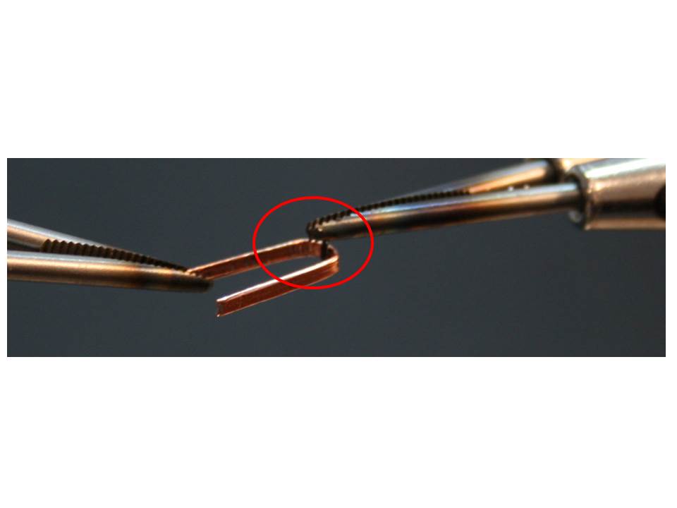
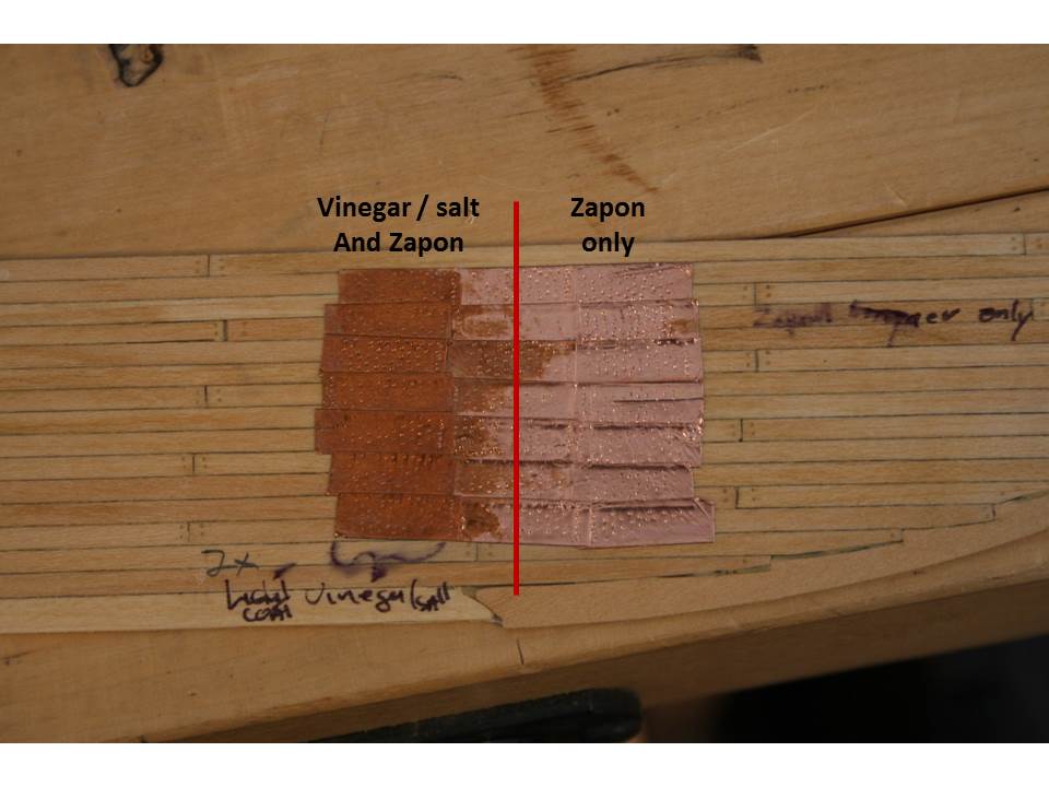
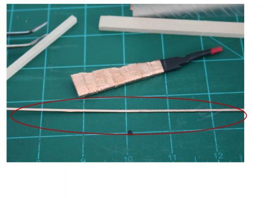
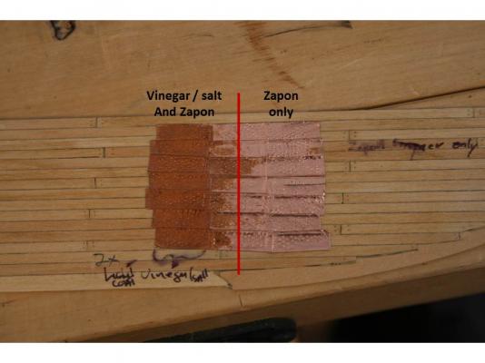
Hi, Well, it might take awhile before I have enough proficiency to solder for my build. I used solder and flux with a pencil torch. I am going to try it again but use paste that comes in an applicator and see if I get anymore control. Meanwhile, I continued work on the pintles and gudgeons using CA. First I wrapped the 1/16th brass strip in the copper used for the hull. Next I used CA to attach the wire to the pintle. Not sure how well the wire pin will hold since the pintle has been coppered, but if it does not I can cut away a narrow strip of copper from the brass where the pin is attached and try again. Before I go much further, I need to make an overall decision about all the copper work. Dirk suggested testing a mixture of vinegar and salt to darken the copper and using Zapon lacquer to seal it. I decided to test it while working on the pintles. Vinegar and salt treatment is on the left side only while both sides received two coats of Zapon. I like the darker, more aged appearance rather than the shiny new copper look, but I am a little worried that I might mess it up when doing the full hull. I would like feedback on which version other members prefer. By the way, Dirk, did you use this method on your Syren? Thanks all, Richard

-
Hi all, I am beginning to learn how to solder small parts. I was curious whether a butane torch, such as a pencil torch, or an iron is preferred for this type of work.. and why. Thanks, Richard
-
Just a quick update. The copper plates were fixed using CA and a tiny applicator I found on line that makes it fairly easy to do precise gluing. I am just trying to learn how to solder in an attempt to create the gudgeon and pintles. The first attempt was a disaster but, on the positive side, I did not burn myself. I am wondering if folks are using a butane pencil torch or a soldering iron. Richard
-
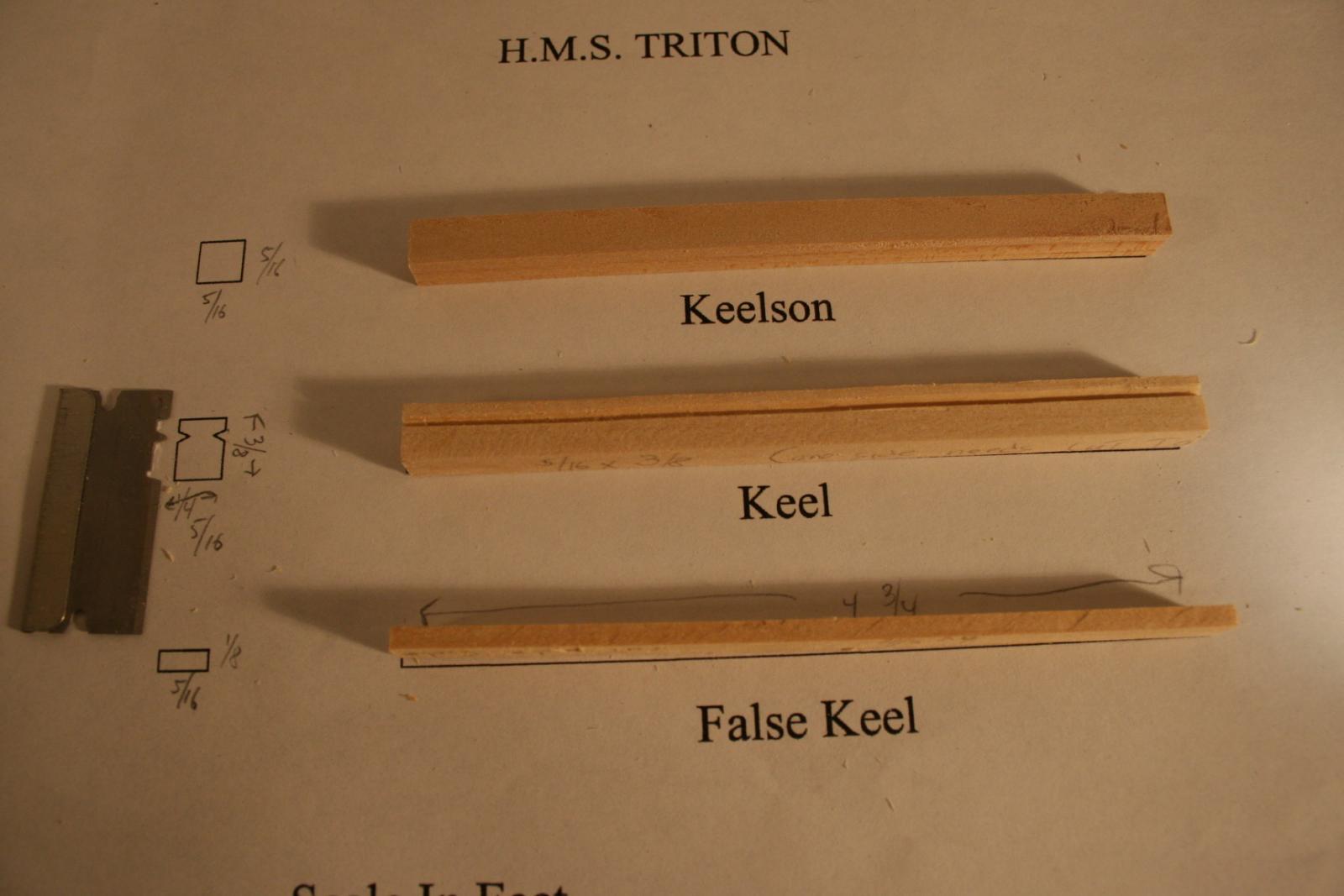
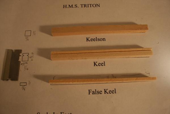
Hi All, I decided to try my hand at Plank on Frame and this seemed a good way to learn. It will also give me a chance to master turning out planks and frames from wood stock so I get to give some of my tools a workout. Here is the first section of work: I have a copy of Ed Tosti's first Naiad book and am using this build to practice fabricating and using some of his tools. Here I have created a scraper from a razor blade to make the rabbet. (I dulled the cutting edge first ... I hate trying to get blood stains out of the wood :- ) Please provide access to the rest of the plans. Thanks Richard
-
Hi Kevin, Looks like a great start. I am considering the Triton cross section also so will look forward to following along. What are the dimensions of the wood you are and how do you plan to cut it to size? I would think the proxxon saw would not be able to handle the size planks you have shown. I have the Byrnes saw and am also looking at his sander but am not sure whether hooking it up to a shop vac will keep the dust down. I work in a room of the house and need to exercise some constraint about sawdust :-) Richard
-
Nigel, thanks for the walk through. I have been following along and you set a great example and supply terrific examples for beginners like me. Richard
-
Dirk, thanks for the CA application tip, will do. Richard
-
Hi Mobbsie, I like the stand, what kind of wood did you use? Richard
-
I found this set of videos showing the construction and firing of a 24 pounder copy from Vasa. It gives a good feel for the impact on the cannon, how it is forced back, etc. when fired. http://www.thehistoryblog.com/archives/32981 Richard
-
US Brig Syren by Gahm - Model Shipways
rtropp replied to Gahm's topic in - Kit build logs for subjects built from 1801 - 1850
Thomas, great method for setting the masts. I was wondering how I was going to do than, now I know. Can't wait to see what you finally decide on the mast foot. The sample you have looks really nice, especially for those who like to use wood as much as possible. Richard. -
Thanks Dirk and Thomas, Whew!! I really didn't want to re-plate. I will have to work at fine tuning my CA application skill. Right now it is too clumsy and would get on the plates. Should take a day or two of practice. Finding the Zapon in the US was a tough search. Finally found one place that had the liquid in stock. When the time comes I will test applying it with an air brush. Dirk, what did you use for a thinner? Thomas, I probably made the process sound worse than it was. Fact is, I pretty much enjoyed working things out. Learning to use my hands and tools were two of the reasons I started all this... and it is fun. Heck, since I retired its not like I have a lot else on my plate. Three of the things on my "bucket List" were model ship building, learning Penjing, and continuing with my drawing and painting. It is really great to now have the time for them. Richard
-
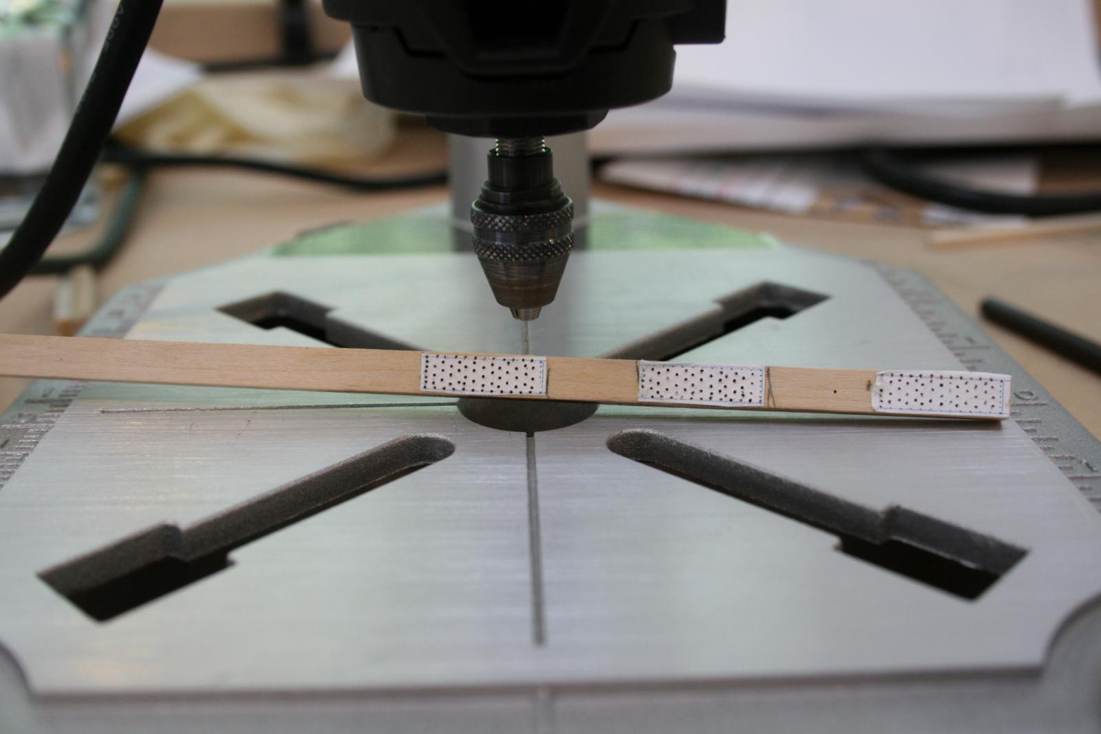
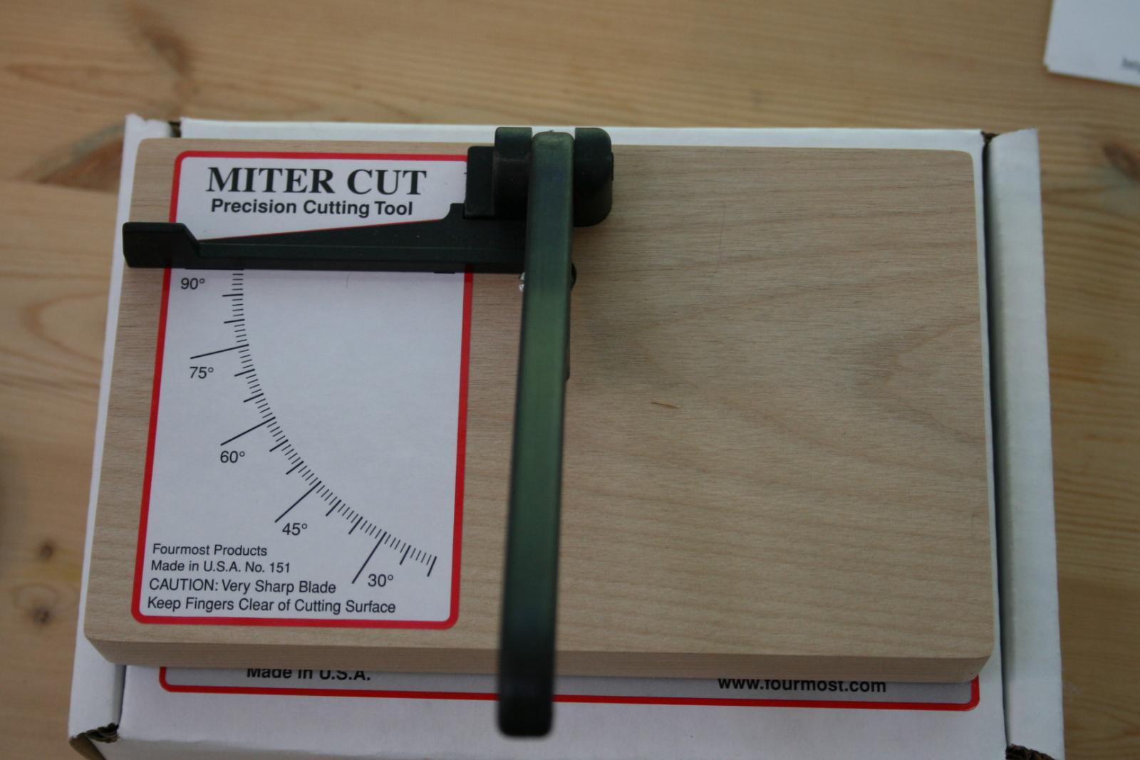
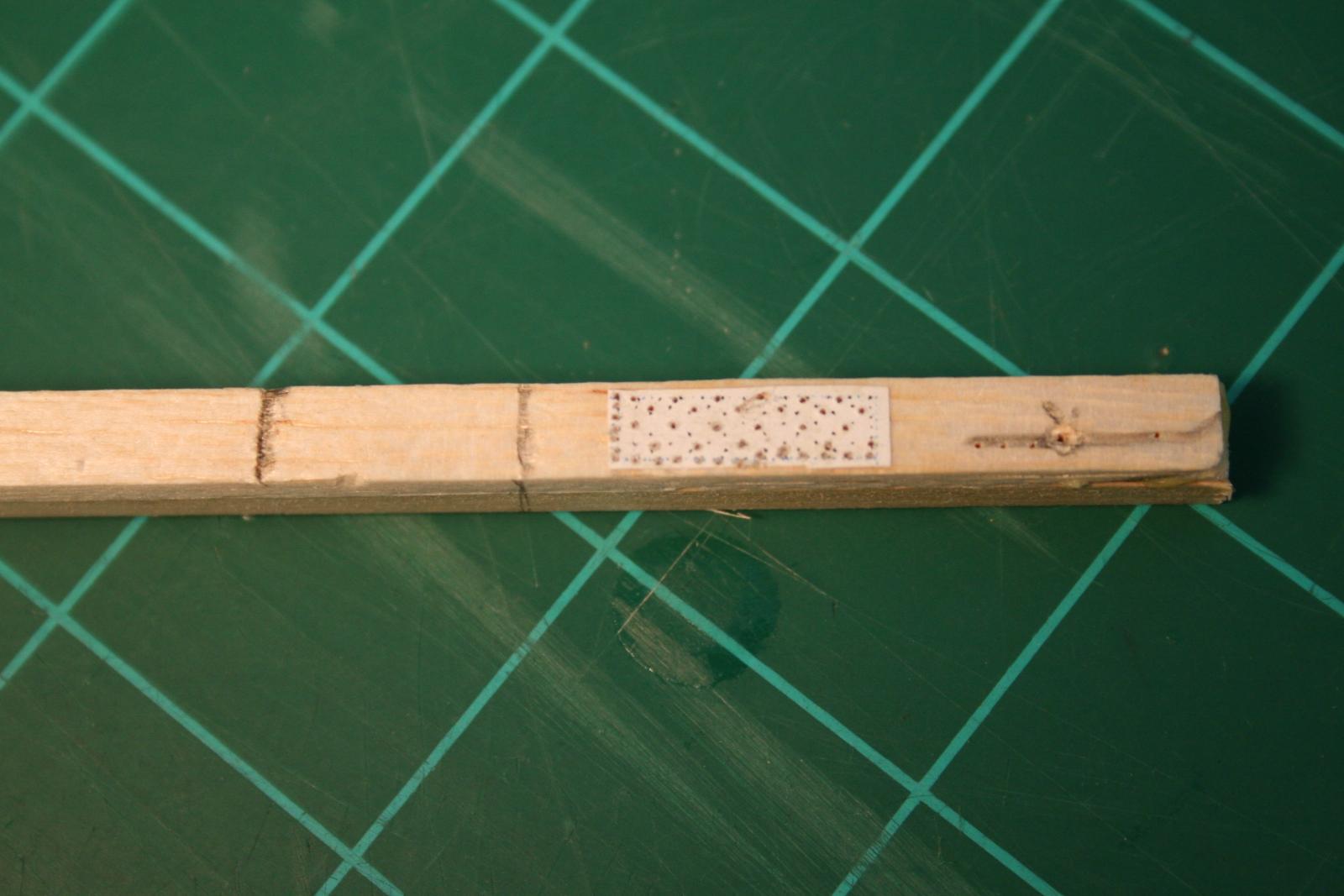
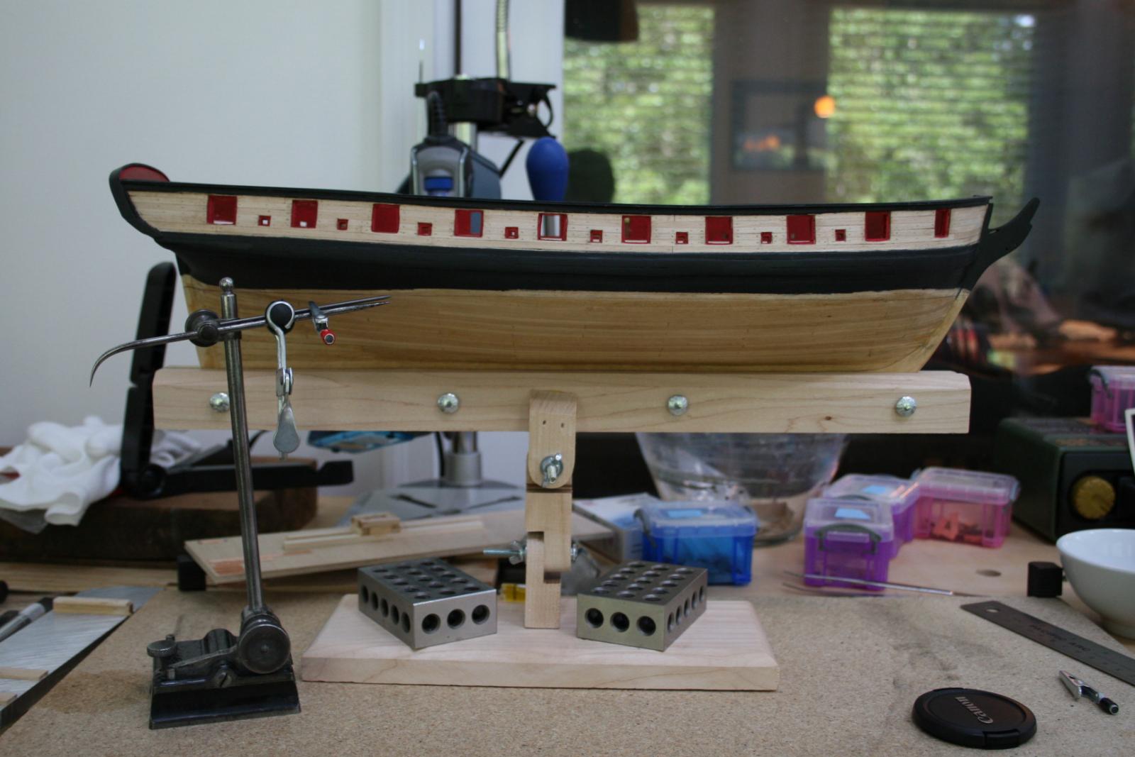
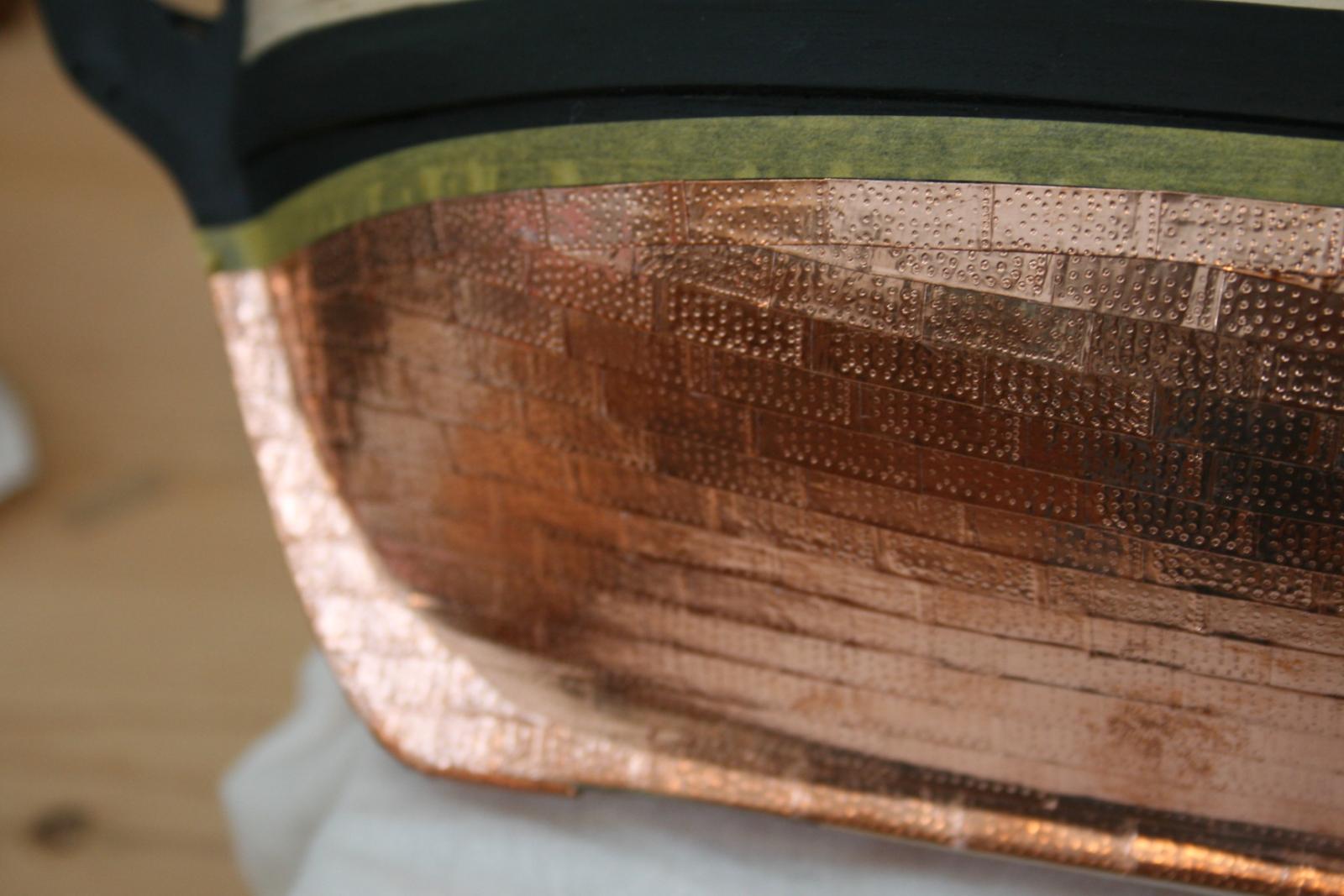
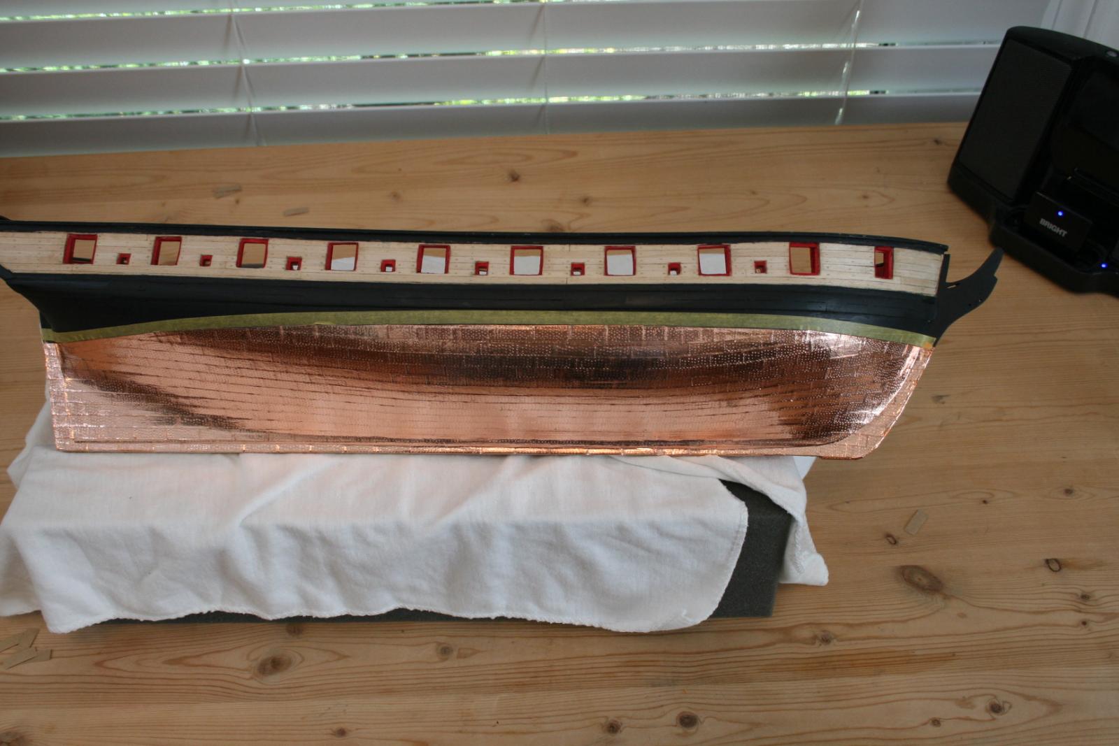
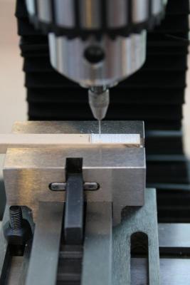
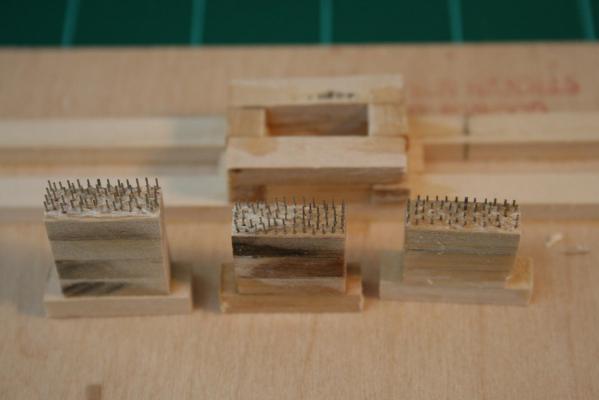
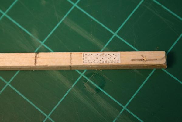
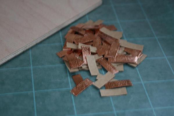
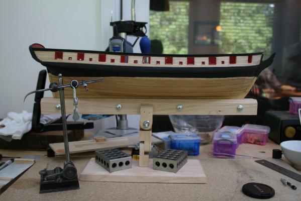
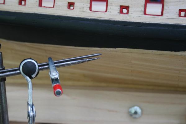
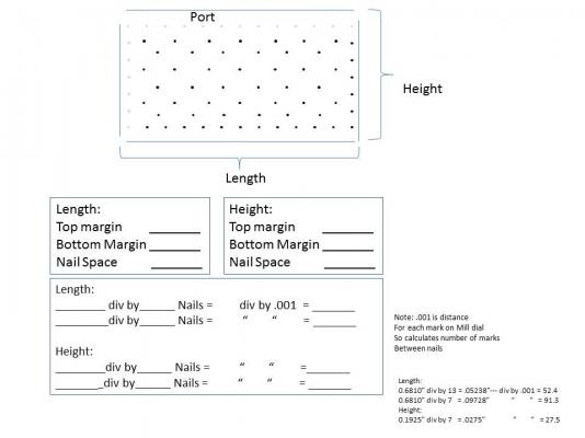
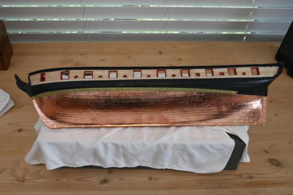
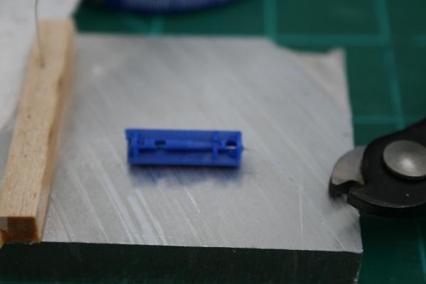
Hi all, I was experiencing delays in posting because of problems trying to post pictures. I was getting pretty frustrated until I went back and re-read the pinned instructions. I was using IE 11. No matter what I tried it would not work. Finally switched to google chrome and it works like a charm... So on to my update. Coppering the hull took forever. There was so much to learn because it was not just creating the stamps but learning how to use various tools, drills, Mill, compound table, wire cutters for high strength stainless steel, etc. I decided to experiment with nails of different diameters per Chuck's suggestion. Being a glutton for punishment I decided to try to follow Thomas Gahm's examples. Thank you Thomas for being very helpful in sending me additional information to help get me started. I could not get the tightness of the nail pattern as small as Thomas did but I did get mine much smaller than the nails supplied with the kit. I used 26 gauge Lancets made for diabetes testing. I separated them from the plastic casing and cut them to size. They are not only thin but very strong requiring a bit of a search for wire cutters whose blades would not be damaged. Went through to or three flush cutters with ruined blades before I figured out they were just not tough enough. Finally went to wire cutters pictured below and just calculated the offset as part of the cut. A quick view of the weeks of trials to get where I am with Copper plating. My first attempt was to print out a pattern and use a Dremel drill in a drilling stand to make the holes. Manually moving the piece to be drilled did not work out. So I decided to use my new Mill and its compound table. Given my starting skills level, I had to work through, how not to break the drill bit, how to change to a higher speed on the mill, how to use the compound table, how to calculate the spacing for the nails, and how to not break the completed stamp when adding the additional wood layers and much more. Took weeks of rework. I made about 15 stamps before I got it where it was acceptable... whew! Below is the set up with the Dremel and stand. I just could not get accurate enough to meet the pattern. Then I decided to try it with the compound table on my Mill. Once I learned how to adjust the belts to increase the speed, the drill bits stopped breaking. I did not use a paper template but relied on calculations as shown further below.: This is a sample of the form I used to calculate spacing for the drilling. One purpose was to translate all to thousandths so I could just count the demarcations on the dial scale of the compound tables vs. eyeballing it : I built the various parts of the stamp: Once the copper was imprinted I had difficulty cutting the plates at a consistent 90 degrees. I found this device below on Amazon. There are others like it but this one is nice and compact. I used a large diameter lead from an art pencil clamped to a height gauge to mark the water line: Finally began putting the plates on the boat: It looks decent but I messed up on the first (Port) side. While I used a cotton glove when touching the copper, I used my bare thumb to separate the copper from the backing. I must have gotten oil from my fingers on the very corner of the glue side of the plate because now many of the corners are lifting. When I did the starboard side I had cotton gloves on both hands and used tweezers to separate the copper from the backing. That side has no problem with corners. Now, I am trying to figure out how to get out of removing all the plates from the port side and having to re-stamp and reapply them. I tested a lacquer spray on a sample piece that I assembled the same way I did the port side. It helps a little but there are still corners coming free. Puleeaze.... Any suggestions on what can be sprayed, applied, etc to avoid having to re plate that side would be welcome. Richard


-
Mark, Very nice. Do the plans supplied include everything shown in your final picture, i.e., decking, posts, cannon, etc.? Thanks Richard
-
Bill, I like the idea of the Thin Rip Jig but am using the Byrnes saw which has 1/2" wide by 1/8" deep slots. Based on your jig, is the slide easily changeable? Richard
-
Just Wishing ...work benches (edited)
rtropp replied to BubbleHead's topic in Modeling tools and Workshop Equipment
For those not in the market for a cheap bench (vs. "pretty"), Home Depot has this six foot bench with a frame made of 2/4's and a nice thick top. I bought one a while ago and it is very stable. the price is $69 so you don't mind drilling holes to anchor equipment. I had not seen it for awhile and noticed them in stock again the other day. Richard -
Has anyone used yellowheart and if so for what? Thanks Richard
-
Thanks Antony richard
-
Antony, I would love to see the steps you follow in putting film on the copper plates. I have been trying to figure out what I might use for my Syren. thanks Richard
-
Brian, What speeds do you use on brass or aluminum? Richard
-
There are a number of threads about this topic in this forum. One that might be helpful is called "milling machine" and was last used in Nov of 2013. One difference is that the Sherline is known for working both metal and wood parts. I am under the impression that the MF70 may be for wood only. ( I would appreciate someone who owns one chiming in.) Another difference is the range of accessories available for the Sherline. These are important if you are going to do more than just basic woodwork. An additional difference, and an important one, is the highest speed each can attain. The MF70 is listed at 20,000 RPM while the top speed of the Sherline (standard unit) is about 2,800 RPM. Big difference... but, there is a split opinion among the users. Some say you need the higher speed when working wood. Others say that you don't, just feed the piece slower. I have an MM micro mill that has specs similar to the Sherline's and I have not had any problems with splitting etc. That said I not used a high speed wood mill so cannot give a hands on comparison. I would be interested in hearing from those who have used both machines. Richard
-
A question about the stepper motors mentioned above. Do they have to be used with cnc computer or can they be used manually. I am not ready to go into a learning cycle for CNC but would like to be able to move/adjust the x-y-z axis using power vs. cranking by hand. Thus far I have not found a solution. I would like to be able to set the power feed to specific x-y-z motions and depths, perhaps with some repeatability. For instance, a set up like that would have helped when drilling pin holes for a copper plating stamp I recently made. I appreciate any thoughts. Richard
-
Hi Chuck I just did my first walk through of this build. I have set it to "follow" and will enjoy the ride. Thanks for all the detail. Richard
- 1,051 replies
-
- 1
-

-
- cheerful
- Syren Ship Model Company
- (and 1 more)
-
The Byrnes Saw "inside and around"
rtropp replied to nobotch's topic in Modeling tools and Workshop Equipment
I emailed Jim and let him know I would buy one also. Richard