Javelin
-
Posts
636 -
Joined
-
Last visited
Content Type
Profiles
Forums
Gallery
Events
Everything posted by Javelin
-
 See @Keith Black, there's a lesson to learn here for you too. 3rd post in the topic and Glen is already starting his paddle wheels. Really no need to wait for the last part 😃 Beautiful hull Glenn. Did you rely on the self adhesive coat (to glue to plastic hulls) from Artwox or did you apply normal wood glue as well?
 -
Good to see you back Nils, hopefully you are fully recovered and may the health issues stay away for a while! Beautiful work on those railings, never an easy task when you try to do it in one piece!
- 311 replies
-
- 4
-

-
- lightship
- Feuerschiff Elbe 1
- (and 1 more)
-
Great job Keith, happy to see you bit the bullet and made those wheels! They, along with the rest of the build, came out brilliant.
-
Well I'm in! A pretty large hull indeed. I am surprised there are so few models around of this iconic vessel. Looking good so far, love the idea of the partially raised propeller.
-
Great new project. However, I doubt the ship in the picture and the one in the painting are the same... I would rely on the painting more, since it clearly shows Columbia on the paddlewheel cover, while the picture doesn't really give a clue to the pictured ship's name....The superstructure with bridge on top etc, seems very different from the painting. Of course it could be an upgraded, later version of Columbia in the picture. The bottle is indeed not something an SIB builder would choose, since that long neck will restrict movement of any tweezer or tools you're about to use. Not very convinced on the ornamental top and bottom of that bottle. It looks like a good framing, but I'm somehow scared of those being a bit too empty and leaving the model appear too small for that bottle. You're "simulation" however looks good so far in that (or any other) regard. Looking forward to the way you'll handle the challenges posed by that neck.
-
You're welcome Ian, with regards to loading something like this, I believe they drive a car in, turn it inside, so the car front faces the stern ramp and drive it towards that ramp on the extreme port side or starboard side. The next car does the same and parks behind the first one. Third comes next and so on. Perhaps two lanes like that. Next lane I assume can stay without turning. During discharge the first two lanes, portside or starboard, can then drive straight out, creating space for the next lane to turn and then drive out. Not sure if that makes any sense.
- 24 replies
-
- 2
-
-
- ferry
- Europic Ferry
- (and 1 more)
-
Is the RCN weaponry, more specifically the SSM and RAM equipment supposed to be installed in these positions? The RAM not being centered I can understand, but I'd at least have expected the SSM (Kongsberg NSM?), to be devided between Portside and Starboard side?
- 52 replies
-
- 1
-
-
- Type 26
- City Class
- (and 2 more)
-
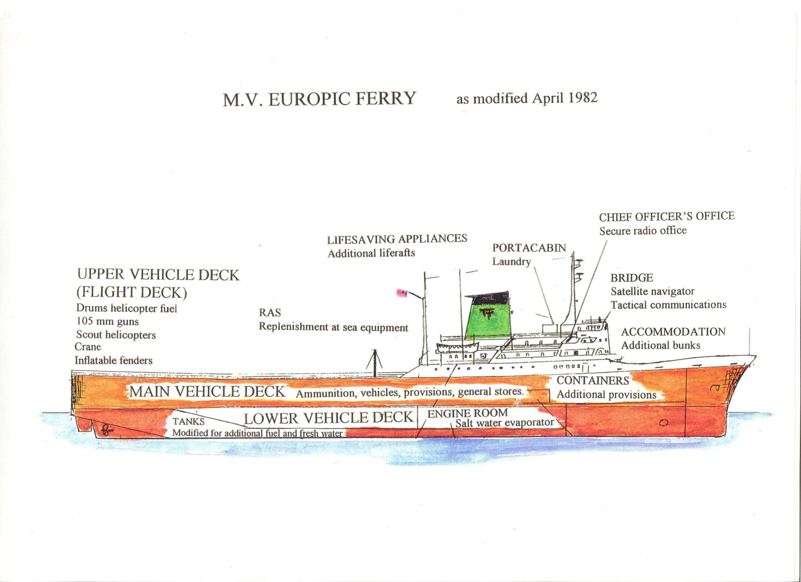
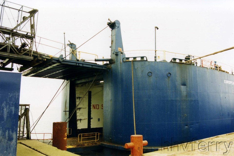
So I had a look around and it's pretty clear to me now. First indication is in this drawing (from: https://www.legasee.org.uk/veteran/chris-clarke/) In the above you can see the ramp on the main vehicle deck going down (starts above the word Tanks and lands below the L from Lower Vehicle Deck). It could apparently be hoisted up to close the main vehicle deck (I assume for a watertightness /safe freeboard reason). This can be seen on the General Arrangement plan as posted in some facebook page (you can view it without an account by searching it through google. Can't seem to link it here... As for the stern ramp, it works double. The vessel was loaded in 2 levels. The upper part of the ramp would hinge down and form a bridge to the upper deck, while the lower part of the stern door would hinge down and form a second bridge to the main vehicle deck. You can see the steel wires of the lower bridge hanging outboard on some of you pictures. Hydraulic pistons are normally used press such gates against a seal in the vessel hull to make it watertight. Not sure why they'd use those on the upper deck though. Perhaps a back-up of the wires? This double ramp is quite typical for ferries, but requires a specialised loading quay with an upper level matching or being adaptable to the height of the decks of the vessel.

- 24 replies
-
- 5
-
-

-
- ferry
- Europic Ferry
- (and 1 more)
-
Hi Ian, she'd have 2 masthead lights (she's more than 50m long), one side light on each side and 1 stern light. As for the platforms on the mast , as far as I can tell from the pictures above, I'd say the top one is an S-band (approx 3-3.5m long) antenna, while the other one is likely an X-band antenna (about 1.5m long). 2 radars are required, however the X-band is the only one that is really required (Search And Rescue Transponders /SART work on X-band frequency). The second radar may therefore be either an S-band or just another X-band. It is quite common for ferries and car carriers to have internal ramps between decks, be it permanent ones or hoistable ones. I'll have a look at some pictures of this vessel and see if I can figure something out.
- 24 replies
-
- 3
-
-

-
- ferry
- Europic Ferry
- (and 1 more)
-
She's gorgeous Bob. Happy you continued and eventually finished her. Love the cupboard too! Fits your varied collection well.
- 261 replies
-
- 3
-
-
-
- Victory Models
- Pegasus
- (and 3 more)
-
You've got yourself a follower now. Interesting subject, right down my alley! I do like the dark blue livery as well. But red's fine too, always makes for an eye catcher on the water. Curious where this will go, but I would indeed try to create some access to the front area. Some cleverly hidden and reinforced handles on that superstructure may help to prevent damage if you make it removable.
- 24 replies
-
- 4
-
-
- ferry
- Europic Ferry
- (and 1 more)
-
Fund raising
Javelin replied to Russ2025's topic in Using the MSW forum - **NO MODELING CONTENT IN THIS SUB-FORUM**
Made my donation today using the link. Didn't have any issues... Perhaps not an accepted type of card? -
Amazing weathering Mark! I Love that open black paint bucket.
-
Hi Paul, Ian, I indeed noticed he (offshore-vessels-drawings.com) was also selling the drawings and pictures for Viking Neptun (from her Eidesvik period) and used some of his pictures for details (like the swimming pool area and aft part of the accomodation). I do doubt he's allowed to sell these as ships drawings are normally quite confidential with notices explicitly stating that they can not be reproduced or used, disclosed or copied without either the owner or shipyard's permission... That is also the reason most companies are not very forthcoming with drawings towards modellers. Occasionally they are helpful and even eager to help, so it never hurts to try and ask.
-
I don't know about you guys, but I'm waiting for those paddle wheels Keith! But I do believe that's fabric.
-
Incredible! As Wefalck said, difficult to distinguish between the original and the model... And to think that most of it will not even be visible!
-
I was wondering about that too Keith, I guess people get sloppy or old over here 😁 @Paul Le Wol, I wouldn't get my hopes up. It's one of my typical preparations I do when I'm at sea. Since I'm unable to build onboard, I do research of ships and ideas at that time. Unfortunately I can't build each project in my limited holidays, so I end up with lots of projects and ideas in various stages of development that will never get built. The choice for VN in this commission at least allows me to use some of that past research, but 1/1250 really isn't my scale...
-
Although I didn't make any real eyebolts yet, I normally use copper or brass wire and turn it around a drill bit to make small round rings or eyebrows. If you use brass wire, it's best to use a 1mm or 1.2mm bit, when using copper a 1.5mm bit will do. You can experiment a bit on what goes best. The advantage of copper is that you can easily cut it with a knife and cut it very straight (I use a lot of copper wire from electrical wiring, since you find a lot of different diameters). They are of course weaker, so you have to be more careful than with brass.
-
Came in a bit late, but she is looking gorgeous!
-
Great subject, but quite a challenge at that scale! I assume you've seen this site and the rather rough drawing contains. https://www.granturismoevents.com/story-wallypower-118-the-coolest-luxury-yacht-in-the-world/ The site mentions 3.5t of fuel per hour for the gas turbine, that would make the bill "only" around $3500 per hour at regular MGO prices.
-
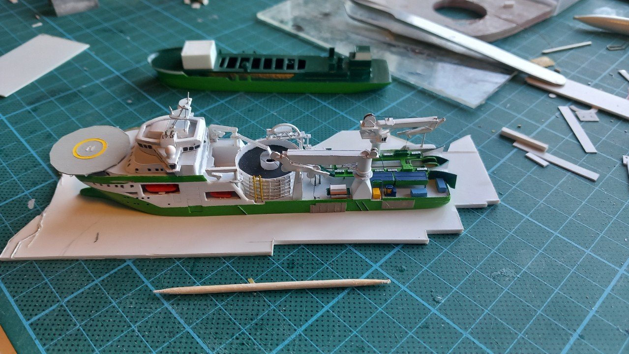
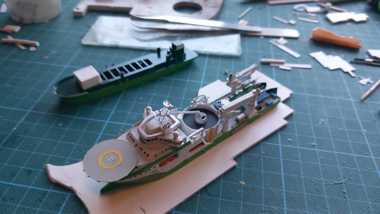
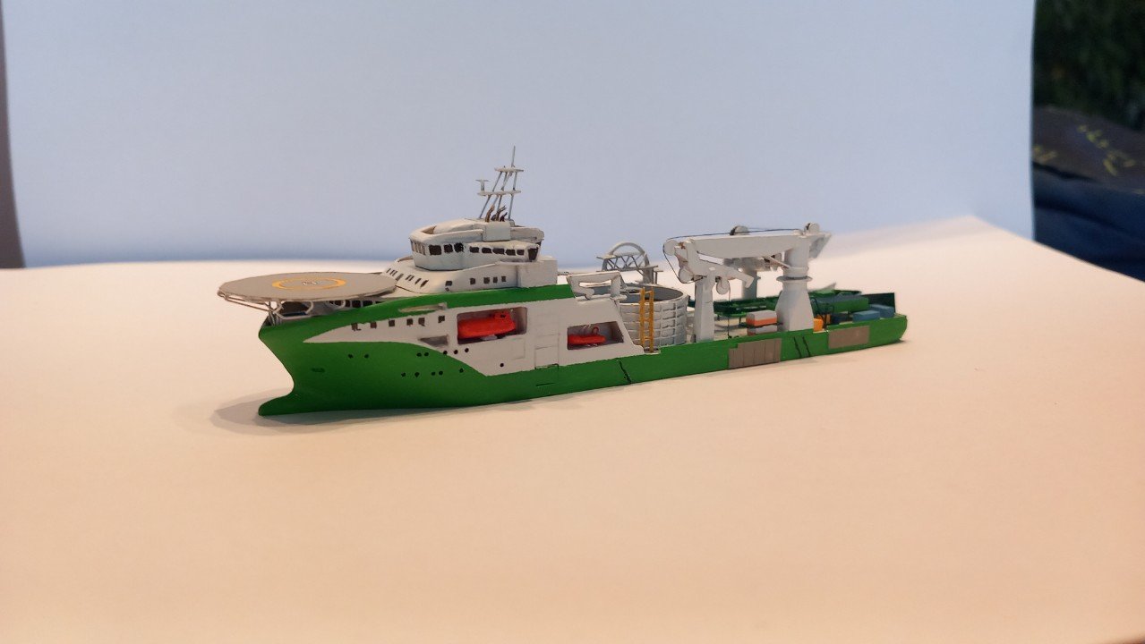
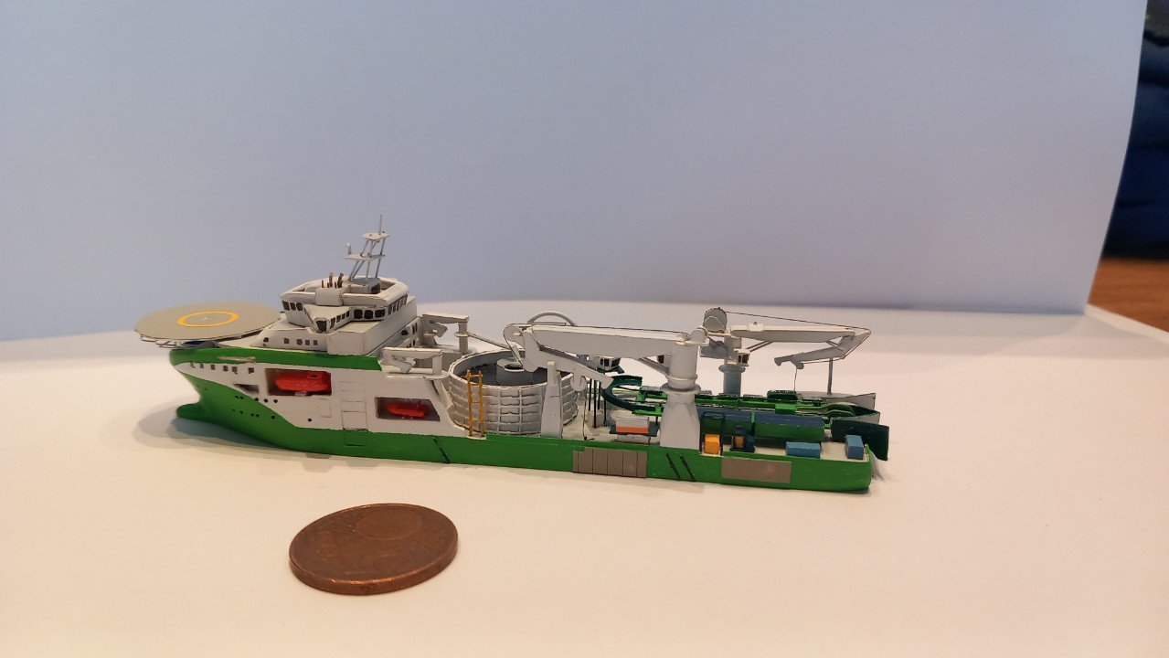
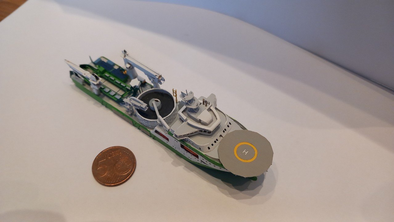
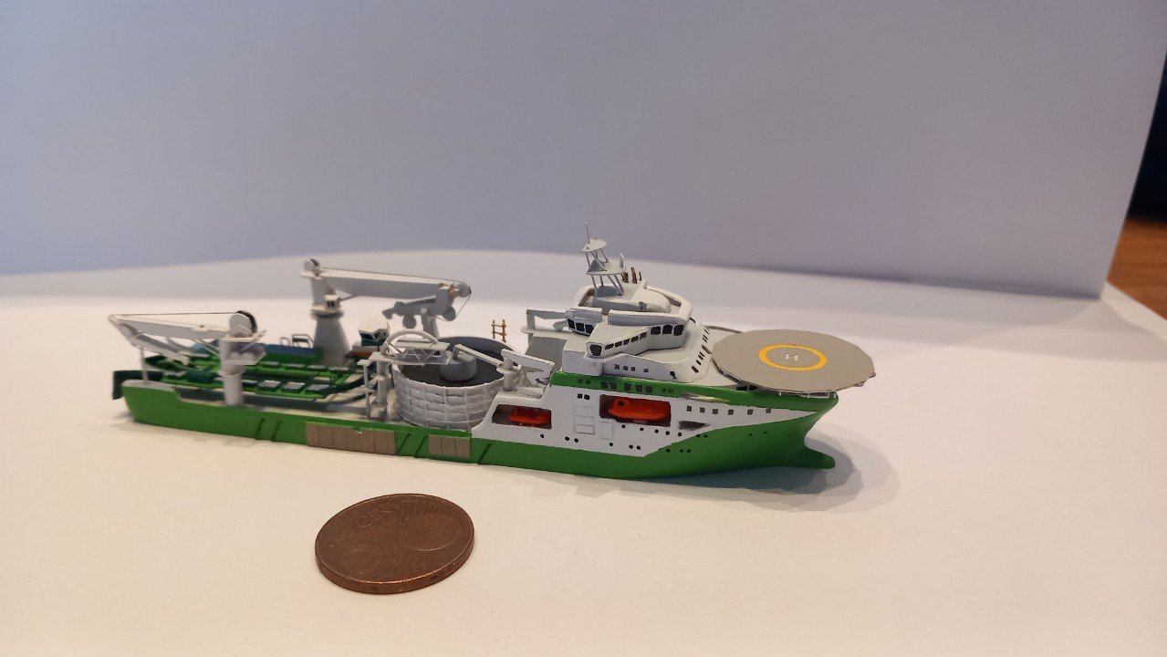
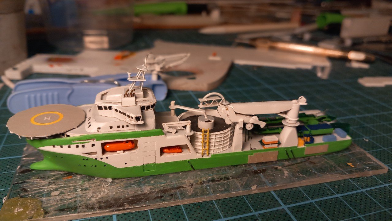
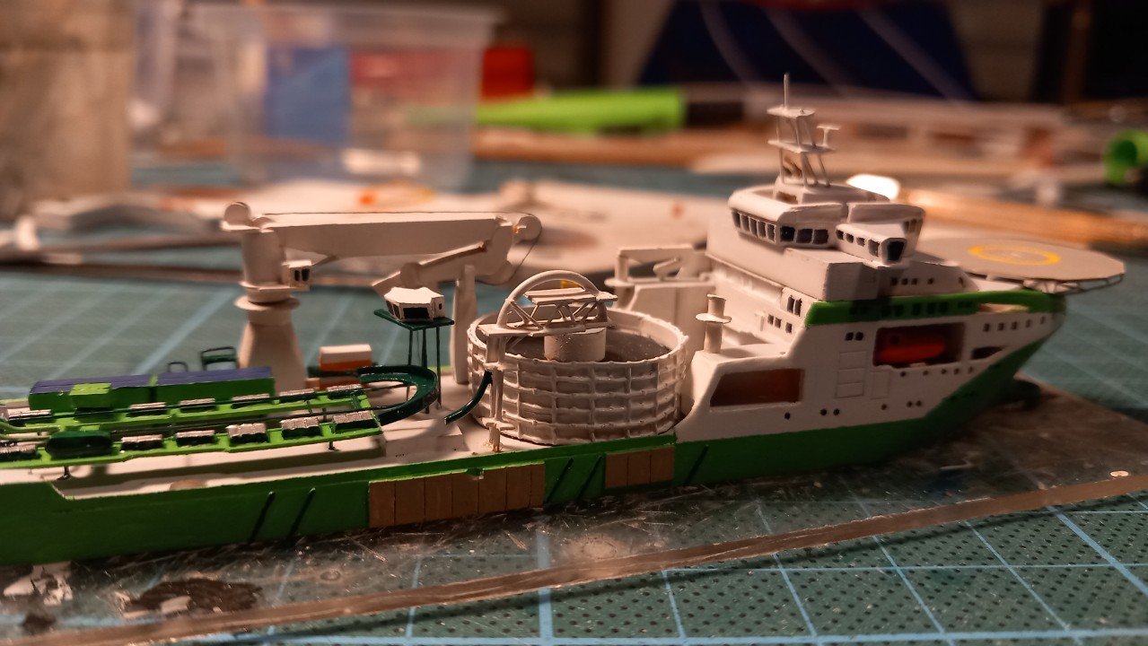
Thanks for the comments and likes. In all my haste to call this one finished, I actually forgot about the 2 large communication domes on either side of the bridge. I've made them from 3mm styrene rod inside my Proxxon and filed them to shape. As you can see, the second ship is also taking shape. @Glen McGuire, the only reason this build went do fast, was my preparation. I have been preparing a 1/100 scale RC build of this ship, which means I was familiar (and thought of solutions) with most of the issues I'd encounter by that integrated accomodation. Also having built a very similar cable layer in the past has helped to detail that installation with precious little info available. Although I have built a Trailing Suction Hopper Dredger before, I believe that Lange Wapper model may be more challenging. I've never been onboard of it and the dark green deck colour makes details on deck very difficult to see in pictures.
-
Ok, she's done. I could probably continue to add details for one month, but probably wouldn't make it any better.
-
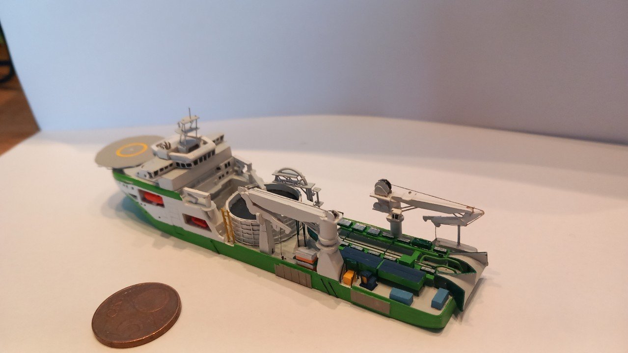
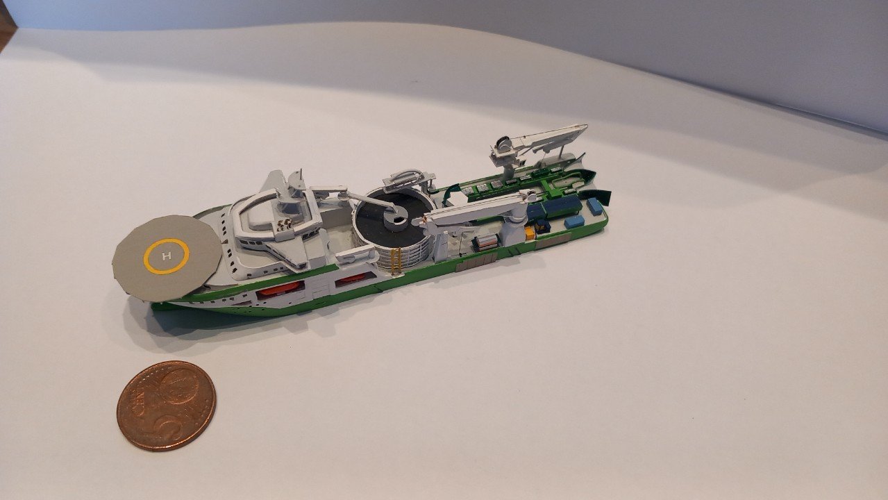
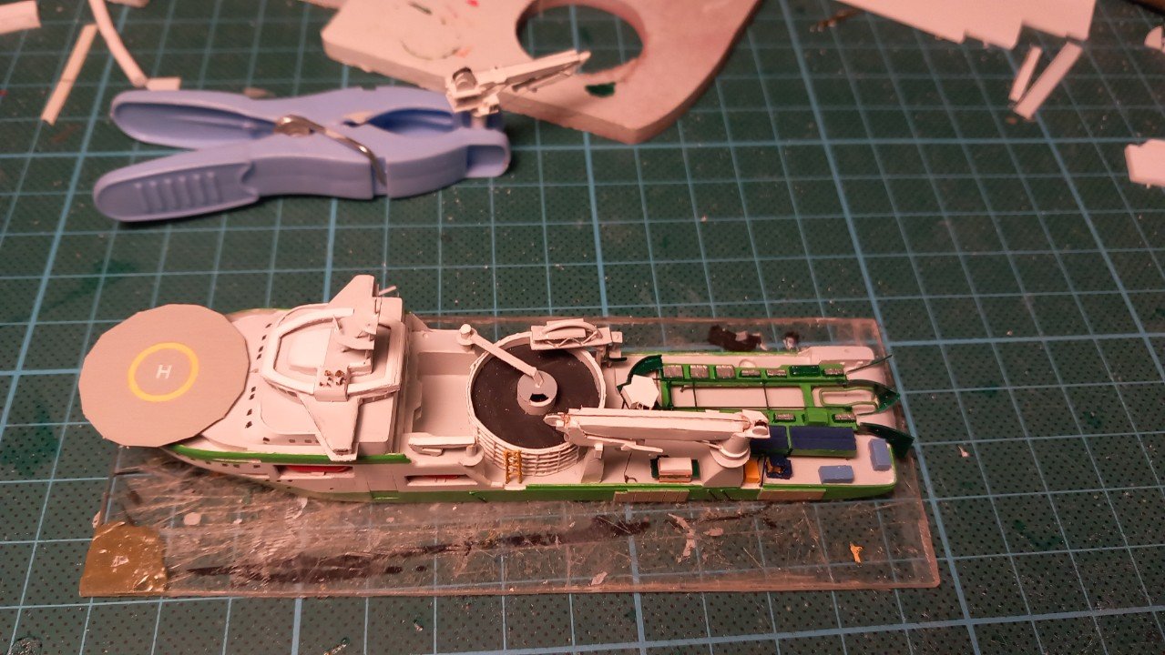
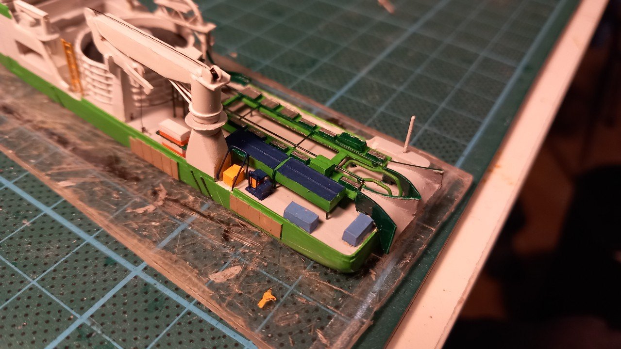
The item I sort of ignored is what I assume a loading tower for the carousel. I assume the cable comes in from deck (dark green bend near the deck) and pulled up over that loading bend over the edge of the carousel. Not sure if that tower can rotate inward and outward to follow the cable or not. Here's a shot of the ROV area. And with the first rescue boat in place. The auxiliary crane is being rigged and then it's time to round this one up.
-
I can't even believe how sharp that work is! (as well as the photography by the way). Quite a complex ship structure, sometimes you wonder how the engineers came up with such a design.