yvesvidal
-
Posts
3,634 -
Joined
-
Last visited
Content Type
Profiles
Forums
Gallery
Events
Everything posted by yvesvidal
-
 Thank you Mike. Yes, coppering and a second planking in visible parts, are in order. After all, I am also entitled to a second planking.... 🙂 like so many other kits. Yves
 -
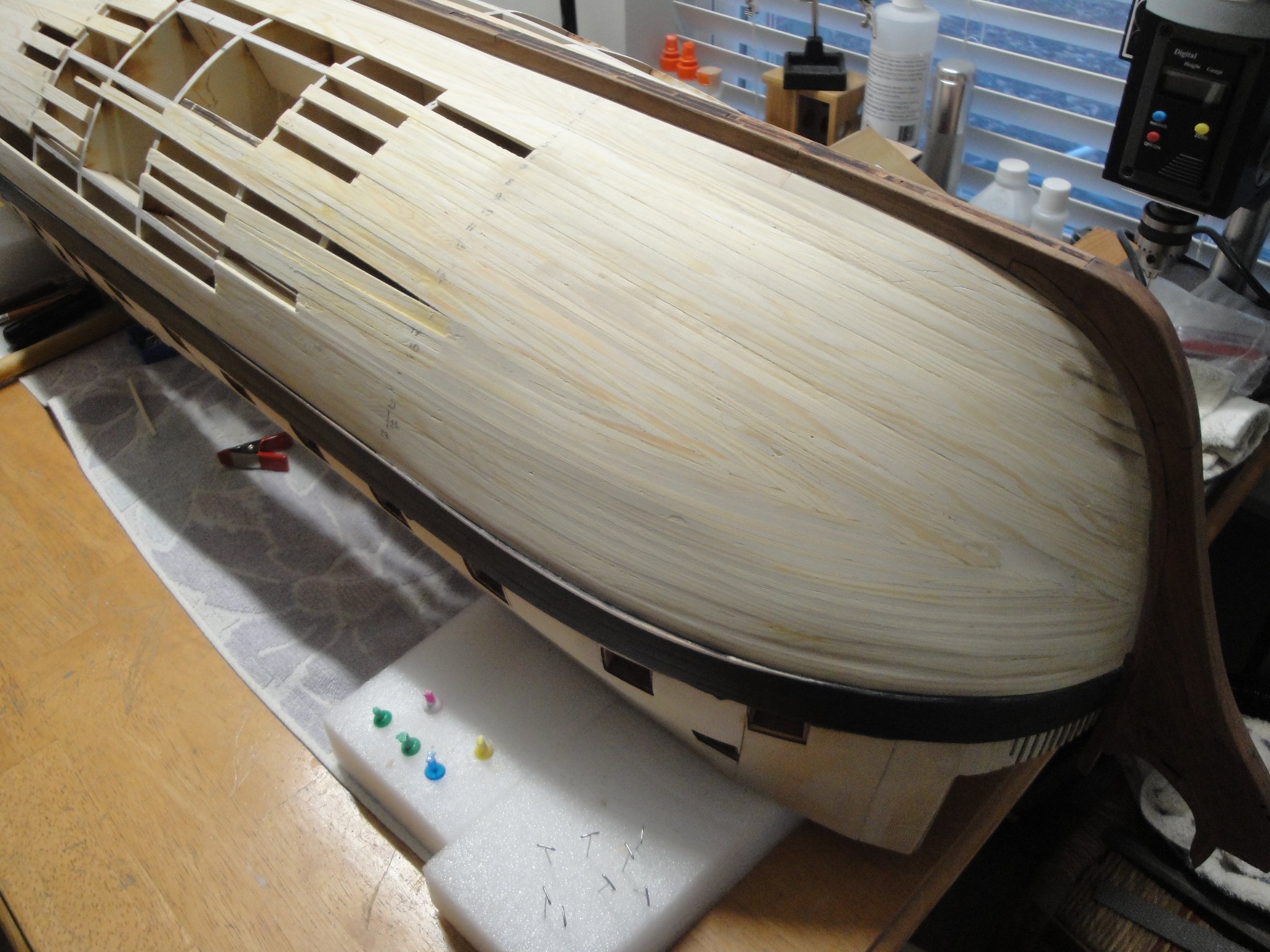
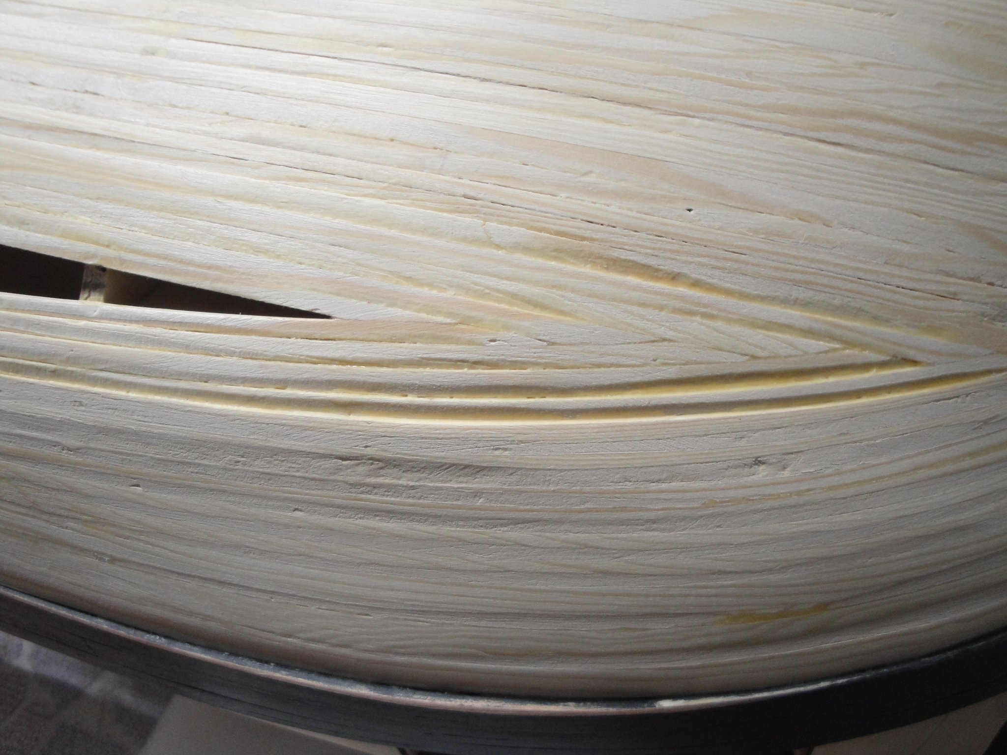
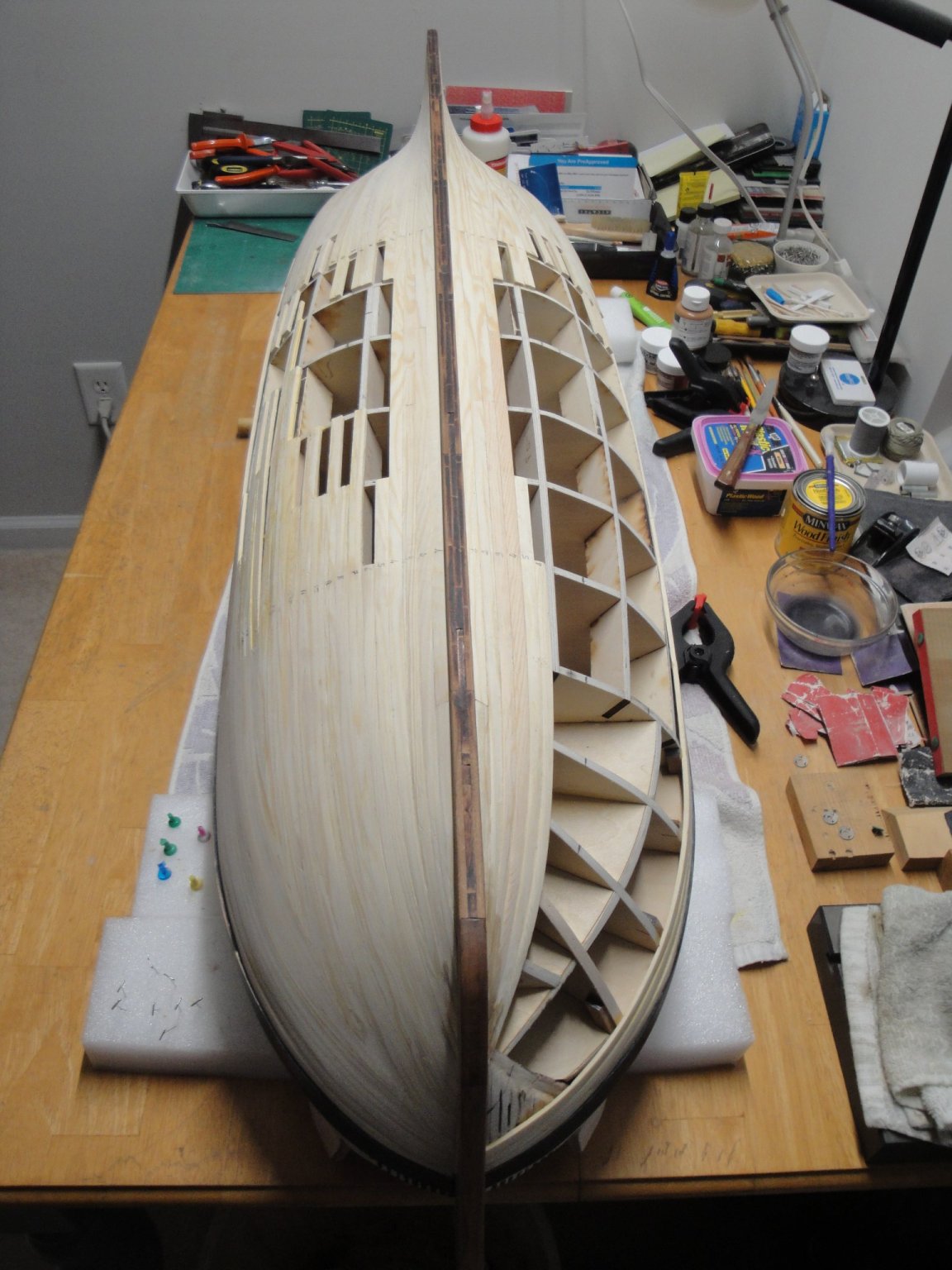
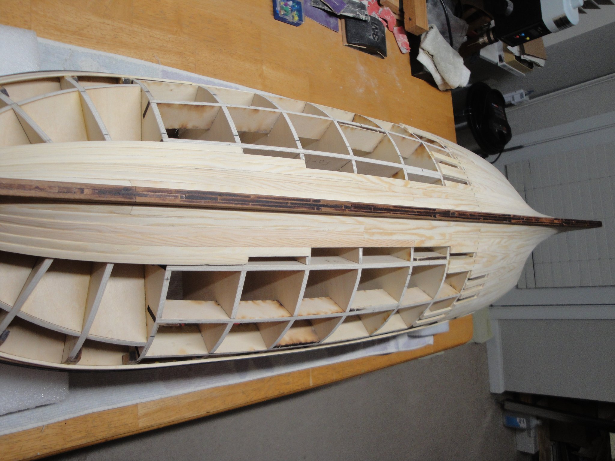
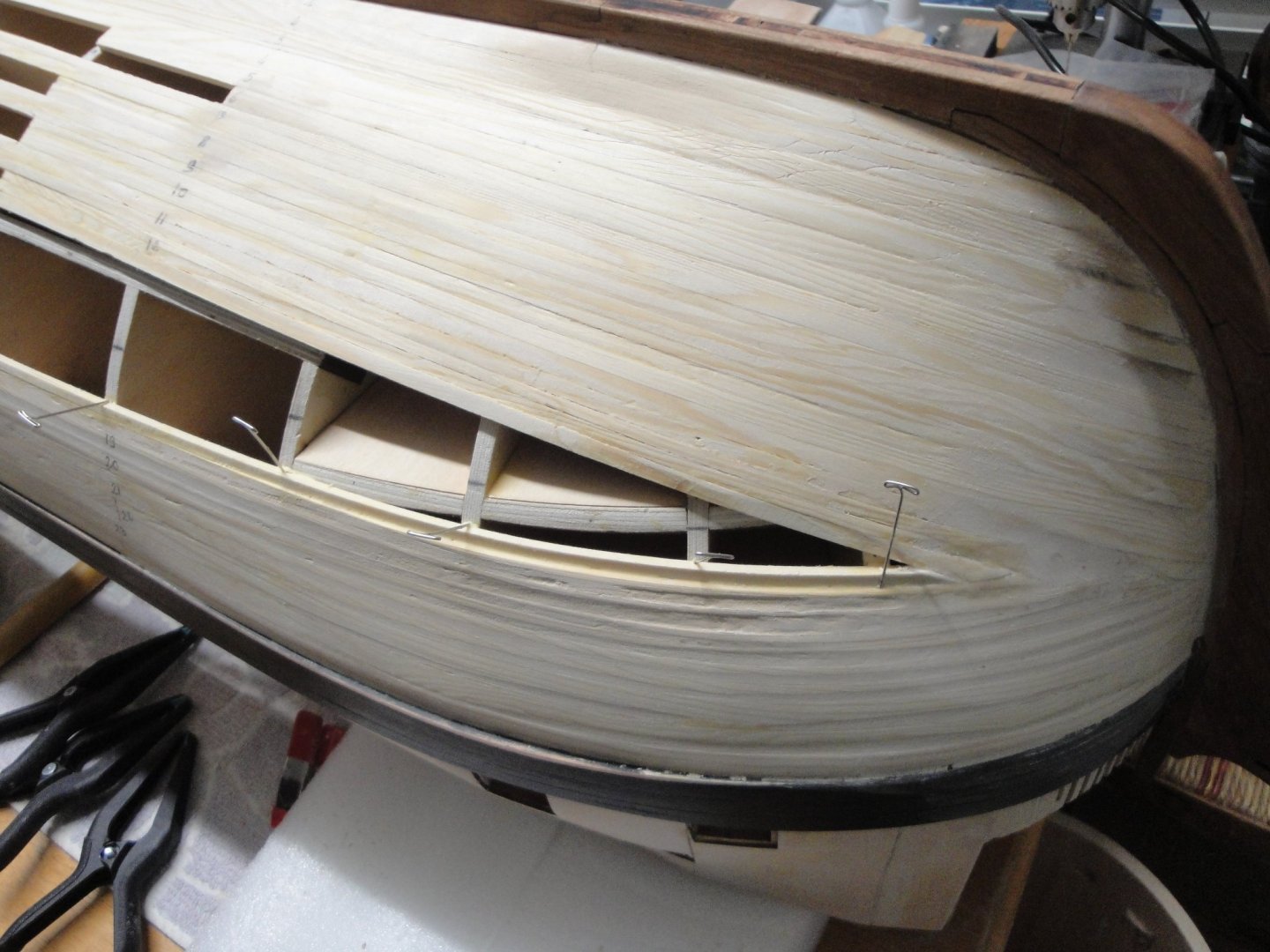
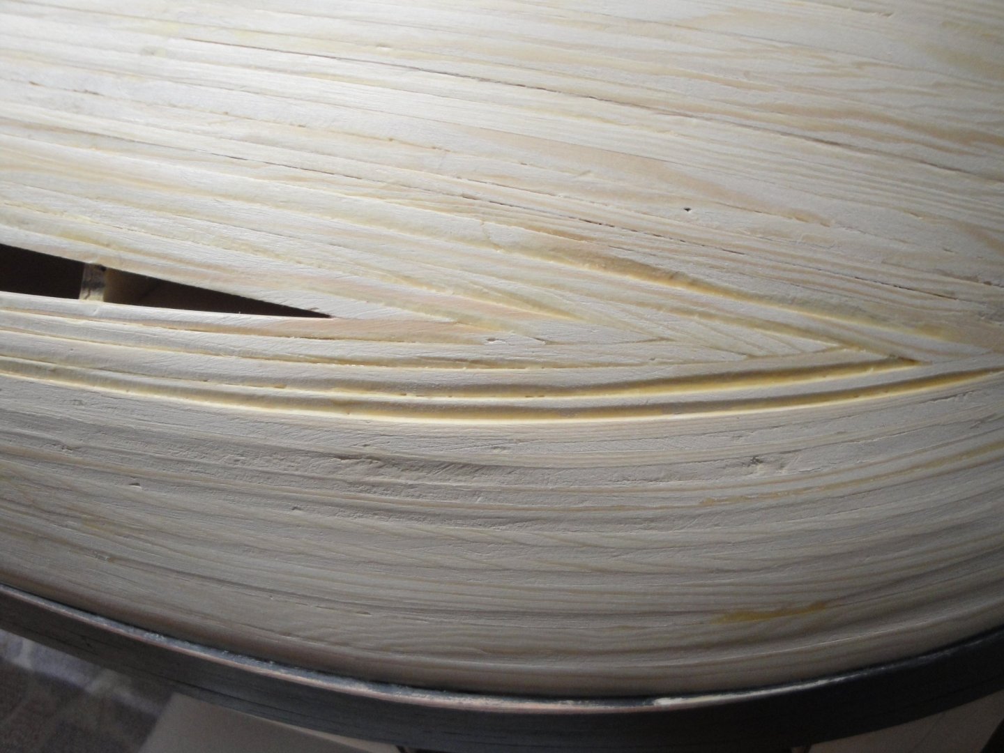
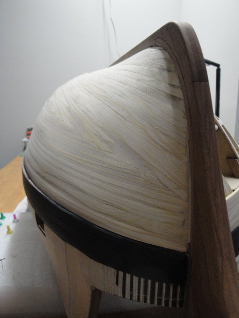
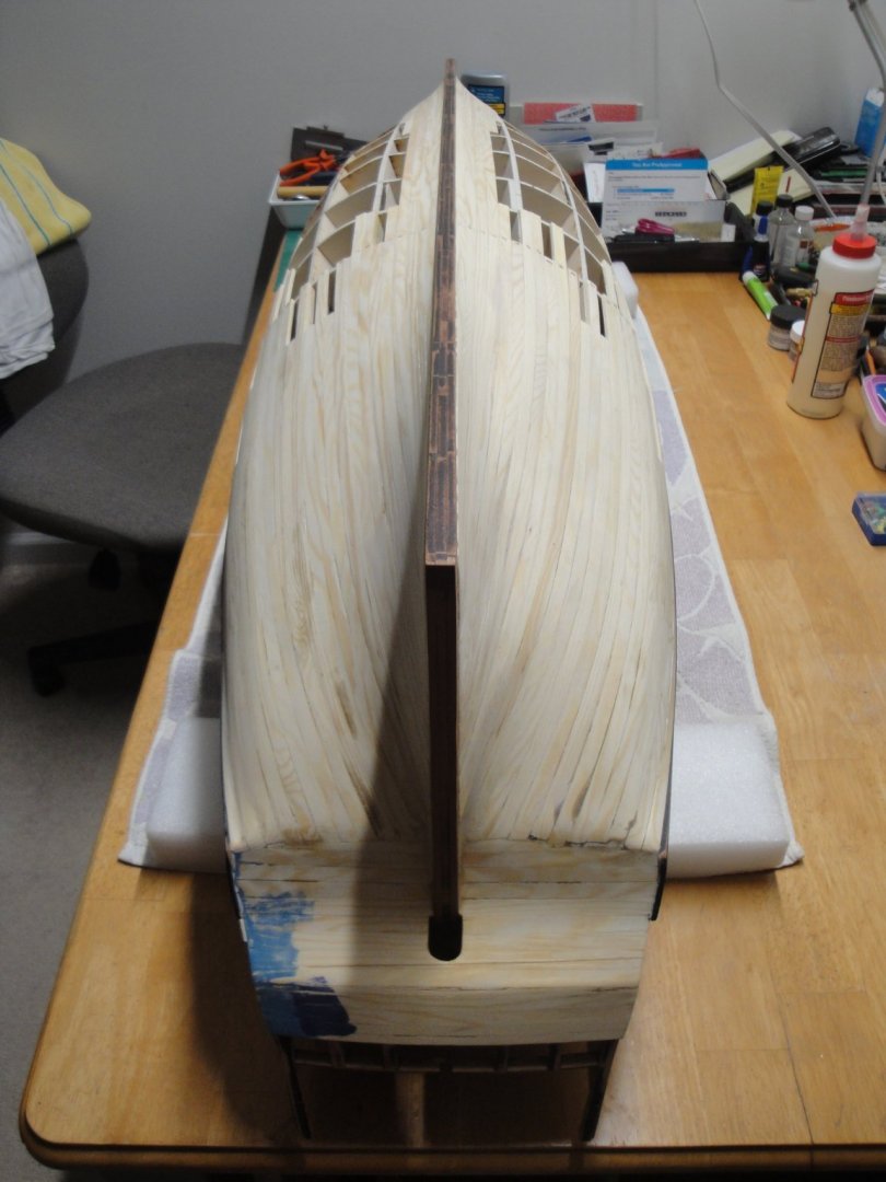
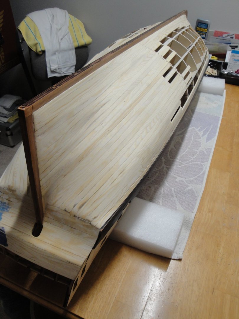
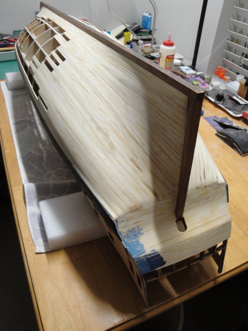
The third quadrant has been completed: I know that a lot of experts will see my construction as blasphemy and heresy to what should be done. It is okay and I understand their point of view. I did the best I could, knowing that this hull will be copper tiled and that most of the planking will be hidden. The most important for me was to embrace the shapes and curves of the hull and to make progress in a relatively decent amount of time. The original planks are 8 mm x 3 mm of poplar/limewood strips. To accommodate the sharp curve of the bow in two dimensions/directions, I decided to slice each plank into two 4 mm x 3 mm strakes. It is a lot easier to handle and I built the planking from the whales up to the mid hull, like a stair with enough steps overlap. Once sanded, the hull is very round and still offers a decent level of sturdiness and solidity. A tiny amount of wood paste is necessary in some places to fill up some of the steps, so created. From the keel down, the planking is placed directly against the bulkeads, until the strakes meet as pictured below: The overall results is rather nice (at least in my humble opinion) and replicates quite accurately the external curves of the ship. It is a lot of work as close to 40 small strakes had to be glued one after the other to create the bow: This is where I stand at this moment: I think I will be finishing the port side of the hull, before moving to the other side: Yves


- 507 replies
-
- 15
-

-
I second Craig: this deck is superb. Yves
-
Beautiful results, Moonbug. I wish I can do as good as you did, on my upcoming hull. Yves
- 419 replies
-
- 2
-
-
- Victory Models
- Pegasus
- (and 2 more)
-
Beautiful! Good thing you painted the strakes separately.... Yves
-
Andrew, Quite often, these furry and wonderful companions are here to help us with karma. It is not uncommon for them to take upon themselves a disease that should have otherwise affected us. We suffer through their loss, but the physical pain in our body is spared by their unconditional love for us. They truly are furry angels of great wisdom and generosity. I have lost quite a few cats (and other animals) during my life and understand very well what you are going through. Yves
-
I am using Thick & Quick Titebond to glue most of the planks on my Bellona 1/48. It gives you about 2-3 minutes maximum of wiggle time. After that it becomes really thick and unusable. The good thing is that it will allow you to press part for two or three minutes with your fingers, when tying it up with clamps is not possible. A good compromise between CA and regular glue. Yves
-
John, That is a great build of a very old kit. I cannot believe that they did not design this hull as planked, as that shape would be very easy to plank correctly. I am glad that you managed to "insert" some planking into its building .... 😉 These paddle boats are some of my favorites and I will be following your build with a lot of interests. Yves
- 238 replies
-
- 1
-
-
- Robert E Lee
- steamboat
- (and 3 more)
-
Dave, thank you for the thorough answers to my questions. Yes, I think I am going to go with the tape too, as the tiles offered by CAF Model are too small and way too expensive. Yves
-
Chris, Thank you for correcting my false assumptions. I like brass (the metal...) but agree with you that 3D printed resin is way superior for accuracy and details. Yves
- 488 replies
-
- 7
-
-
- Indefatigable
- Vanguard Models
- (and 1 more)
-
David, This copper tiling is looking fabulous. Could you tell us what kind of copper ribbon did you use (Brand)? Thickness? Backing (clear or black)? Width? How did you prepare the wood of the hull to get a good adhesion? I will have to copper tile my Bellona (1/48th) soon and I am trying to learn the process and follow the recipes of people who had successful results. Thanks in advance. Yves
- 91 replies
-
- 1
-
-
- Speedy
- Vanguard Models
- (and 1 more)
-
Very promising kit. I like the details on the gun carriage wheels. The 3D printed guns are very crisp and usually better detailed than brass guns. I understand that brass guns would impact negatively the final price of the kit with so much armament, and 3D printed guns will reduce, weight, cost and already have the right color. Yves
- 488 replies
-
- 7
-
-
- Indefatigable
- Vanguard Models
- (and 1 more)
-
Chris, I am very glad to see the Master of Cruise Liners back on the saddle. Still waiting to see that 1/200 Titanic kit.... 🙂 Yves
- 24 replies
-
- 7
-
-

-
- Queen Elizabeth 2
- Gunze Sangyo
- (and 1 more)
-
Kevin, you may want to organize all these wires as they will not fit inside the hull. Also, the light leaking out of the modules will look ugly, through the openings of the deck. Yves
-
Mike, Nothing is double planked. The hull is supposed to be copper tiled and that is probably where I am going. Above the water line, I am planning to use the maple planks of 0.4 mm thick (same width as the main limewood planks, 8 mm) and pretend to have a nicer planking arrangement. We will see how it goes. Yves
-
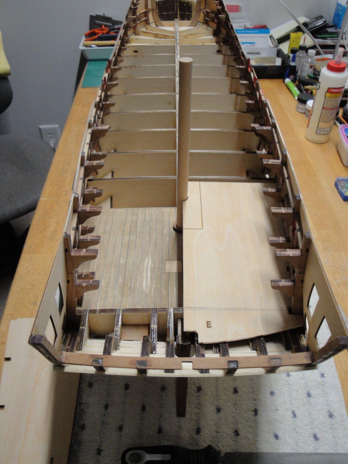
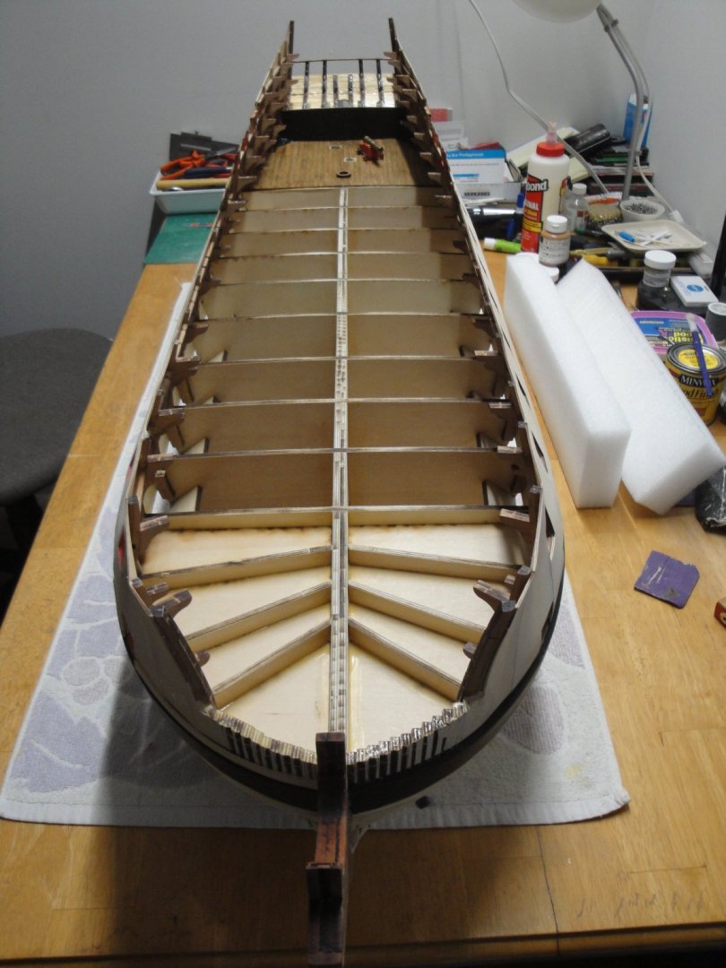
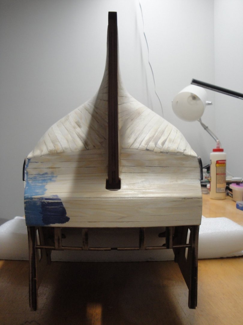
Well, there is not much I can do at the stern at this stage of the hull building: It is time to move the construction crew to the bow: Yves
-
Turangi, This is a gorgeous diorama, beautifully executed. The model is stunning and the long wooden planks are perfectly displayed. I would just place a few 4x4 pieces of wood to insulate the planks from the ground. Wood was never placed directly on the ground. Yves
-
That Vallejo Royal Blue color is stunning. Beautiful hull. Yves
-
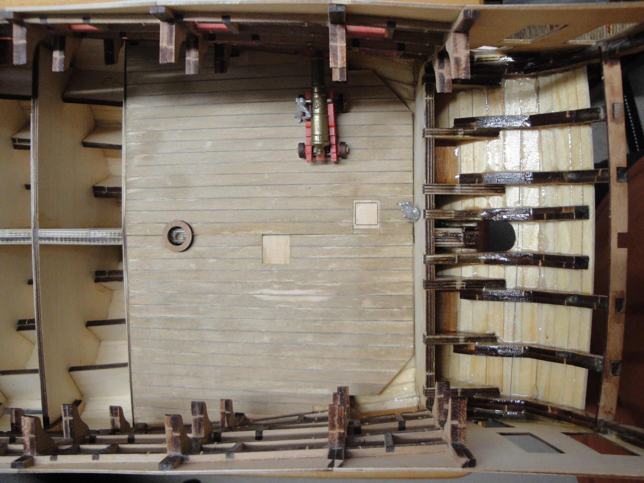
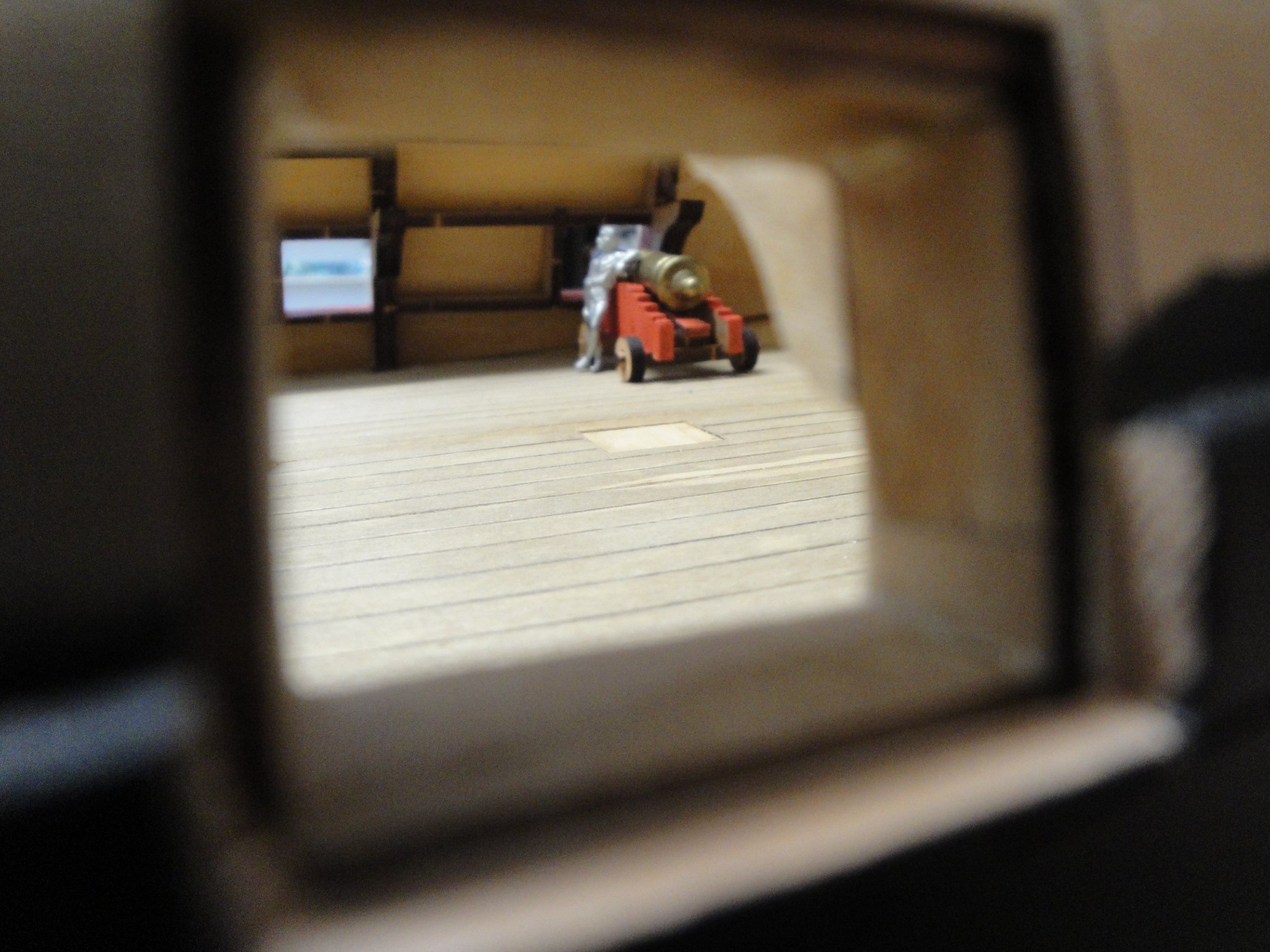
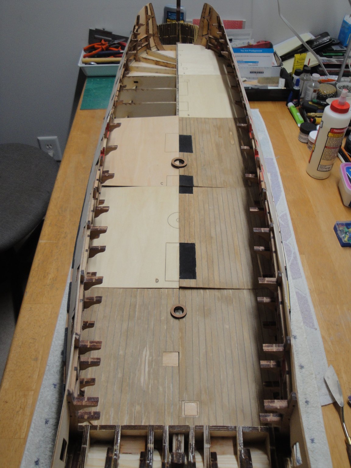
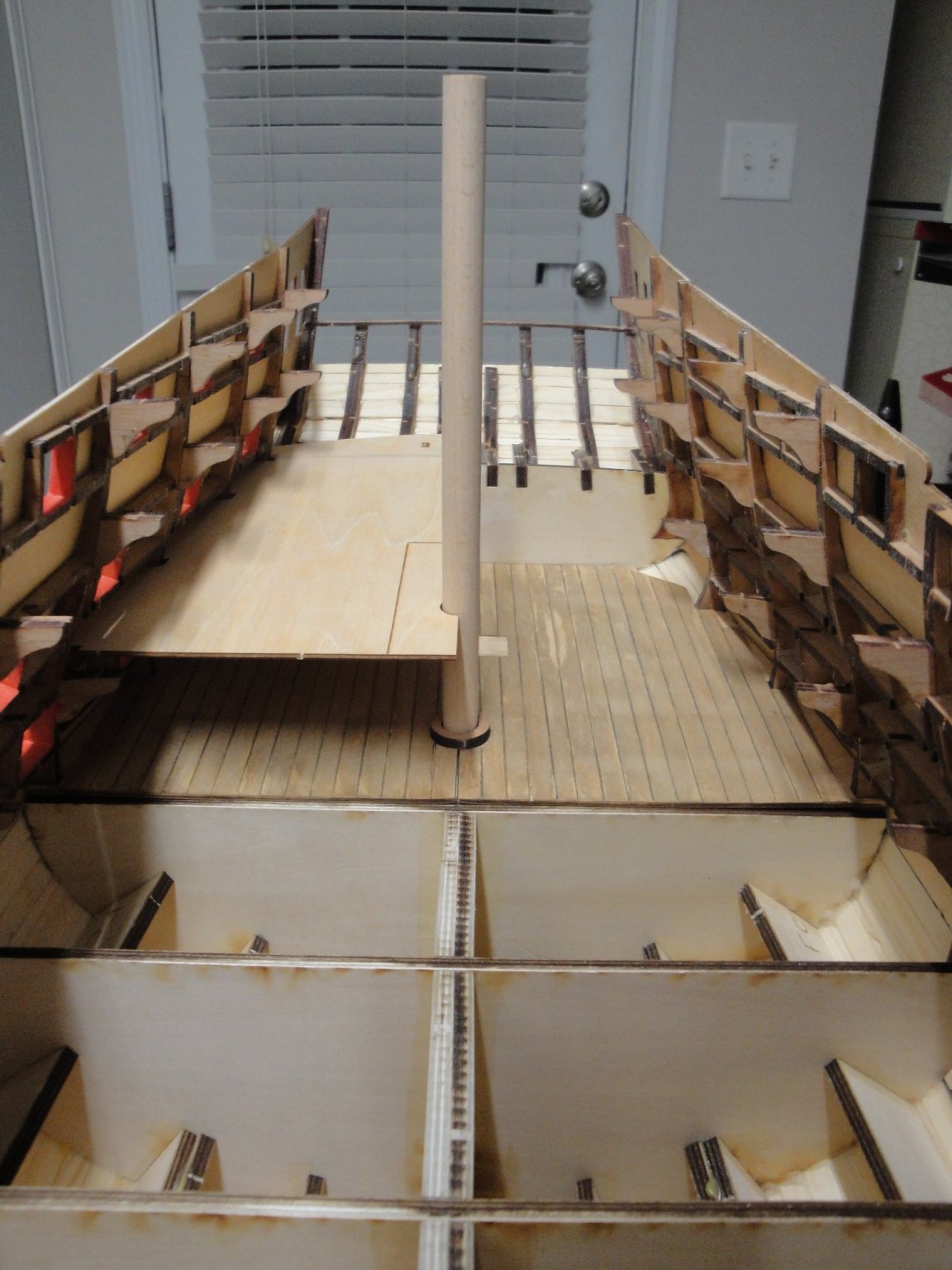
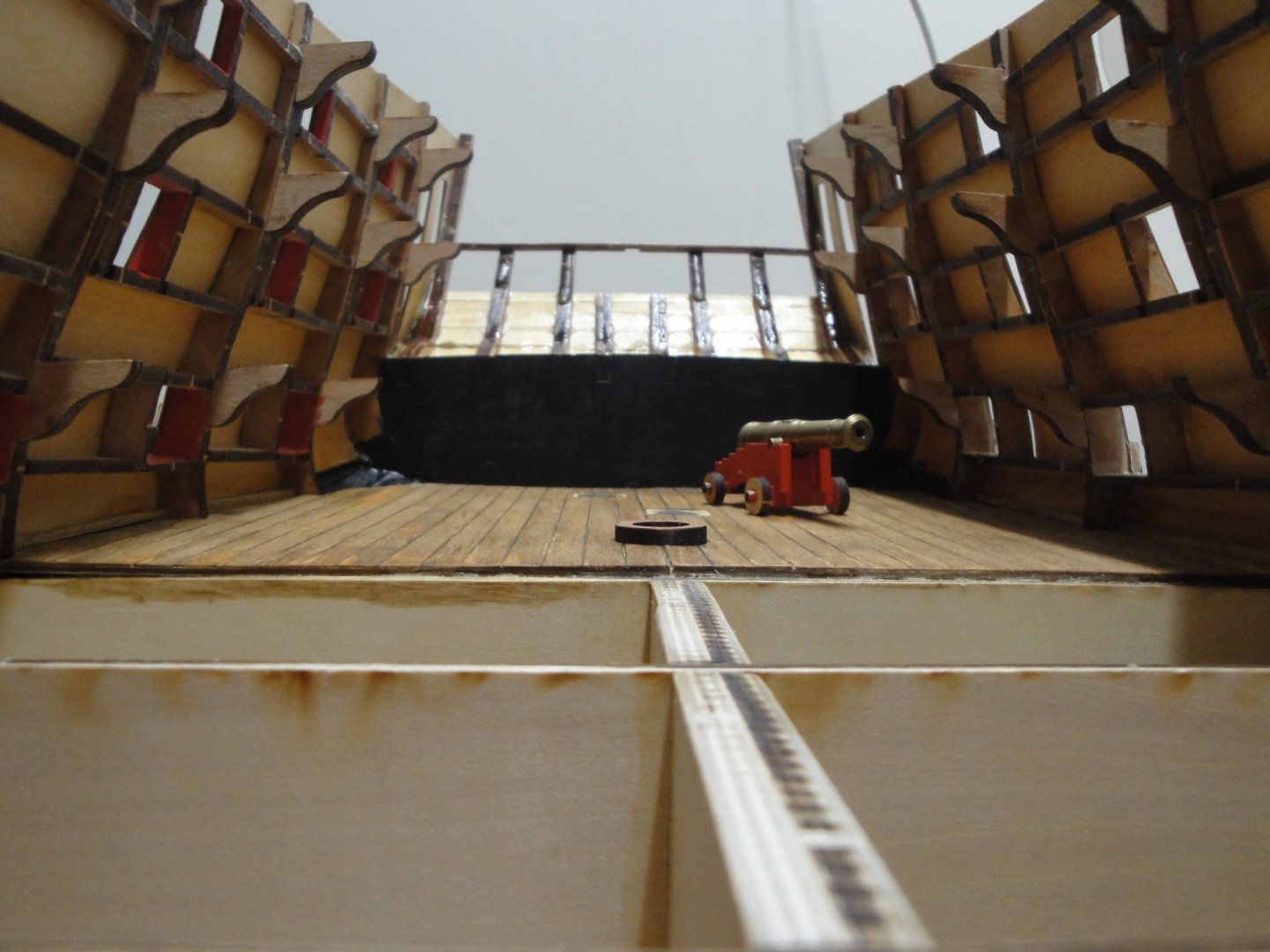
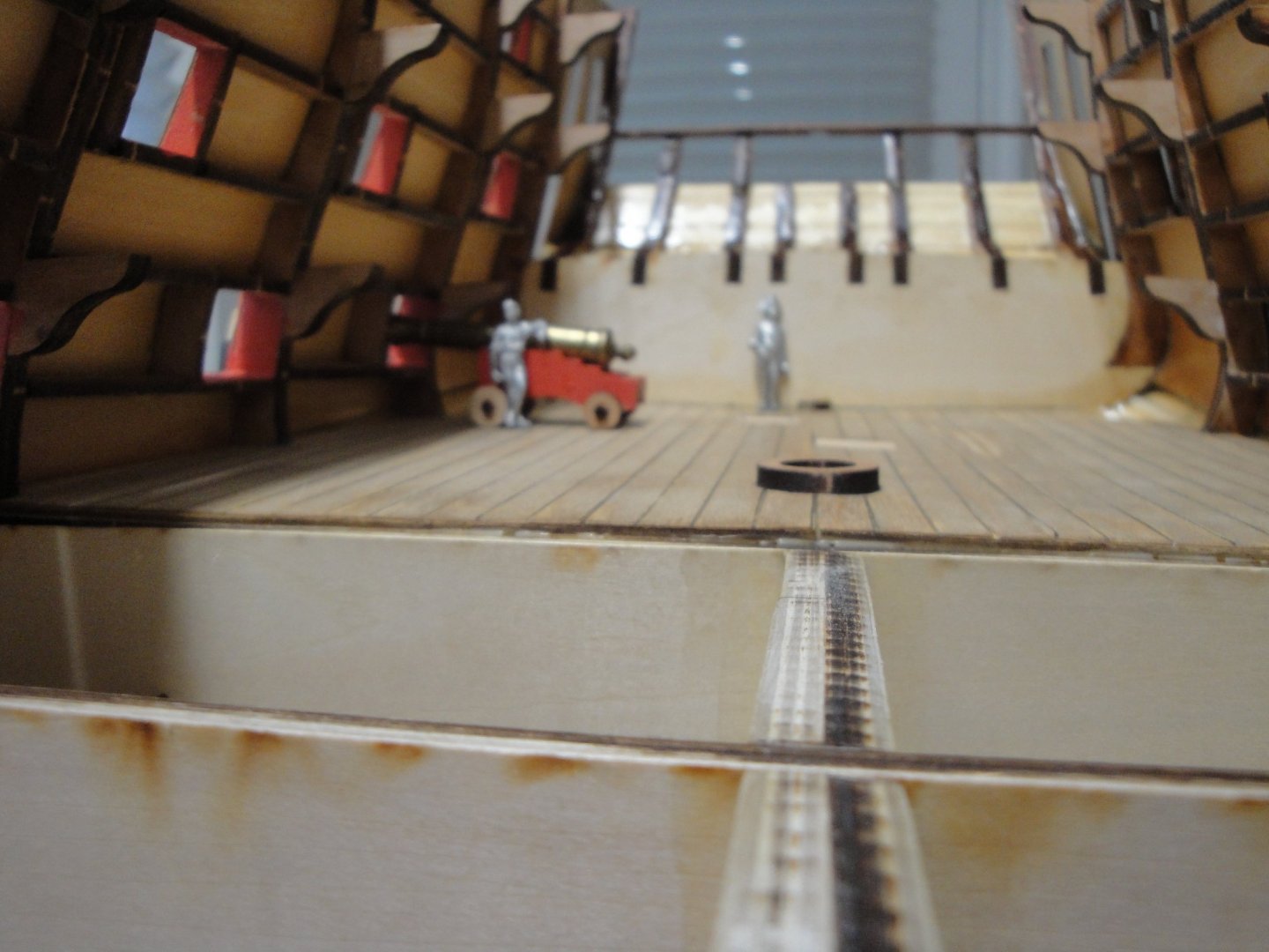
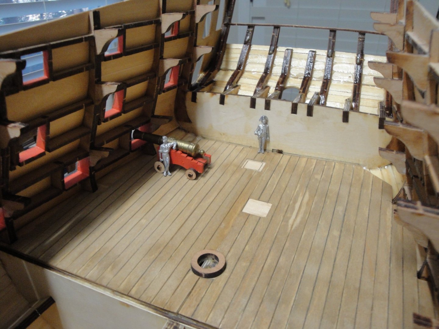
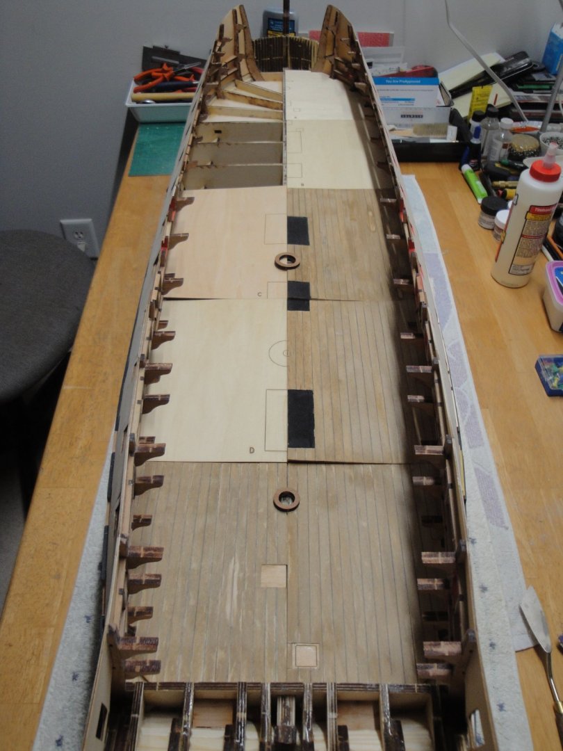
I just glued the rear gun deck section. The hull has been coated with resin and so the deck can be installed permanently: The figures (AMATI 35 mm) may be a tad too small, although 35 mm is about right for 1/48th scale: A goofy picture: Yves


- 507 replies
-
- 10
-
-

-
Not really a "scale model" per say, but Stefan D. is currently the Master at 3D rendering and has published a large number of absolute references and books on the subject of Battleships. Yves
-
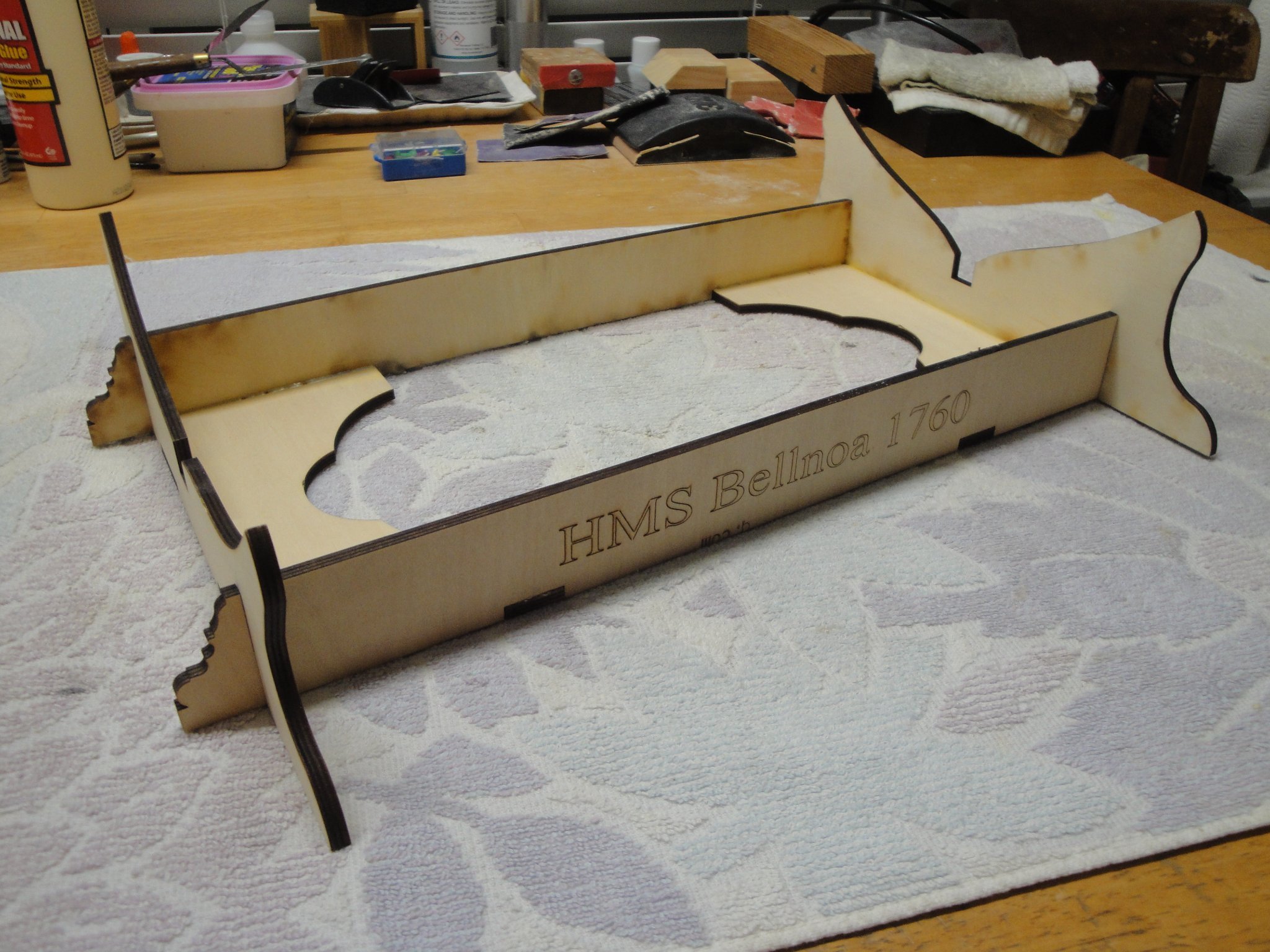
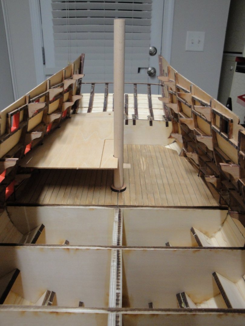
Oh, I forgot to present the stand.... available in Session #4 only..... Shame on CAF for that one, since you really need it during Session #2. On top of that they cannot even spell Bellona correctly.... Yves

-
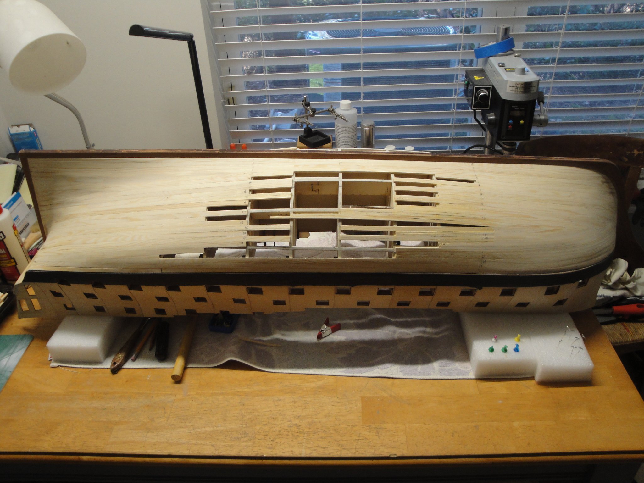
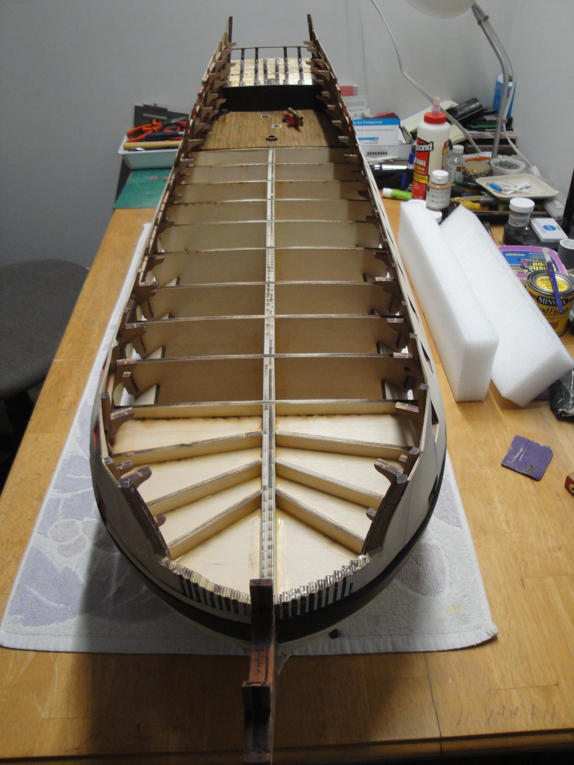
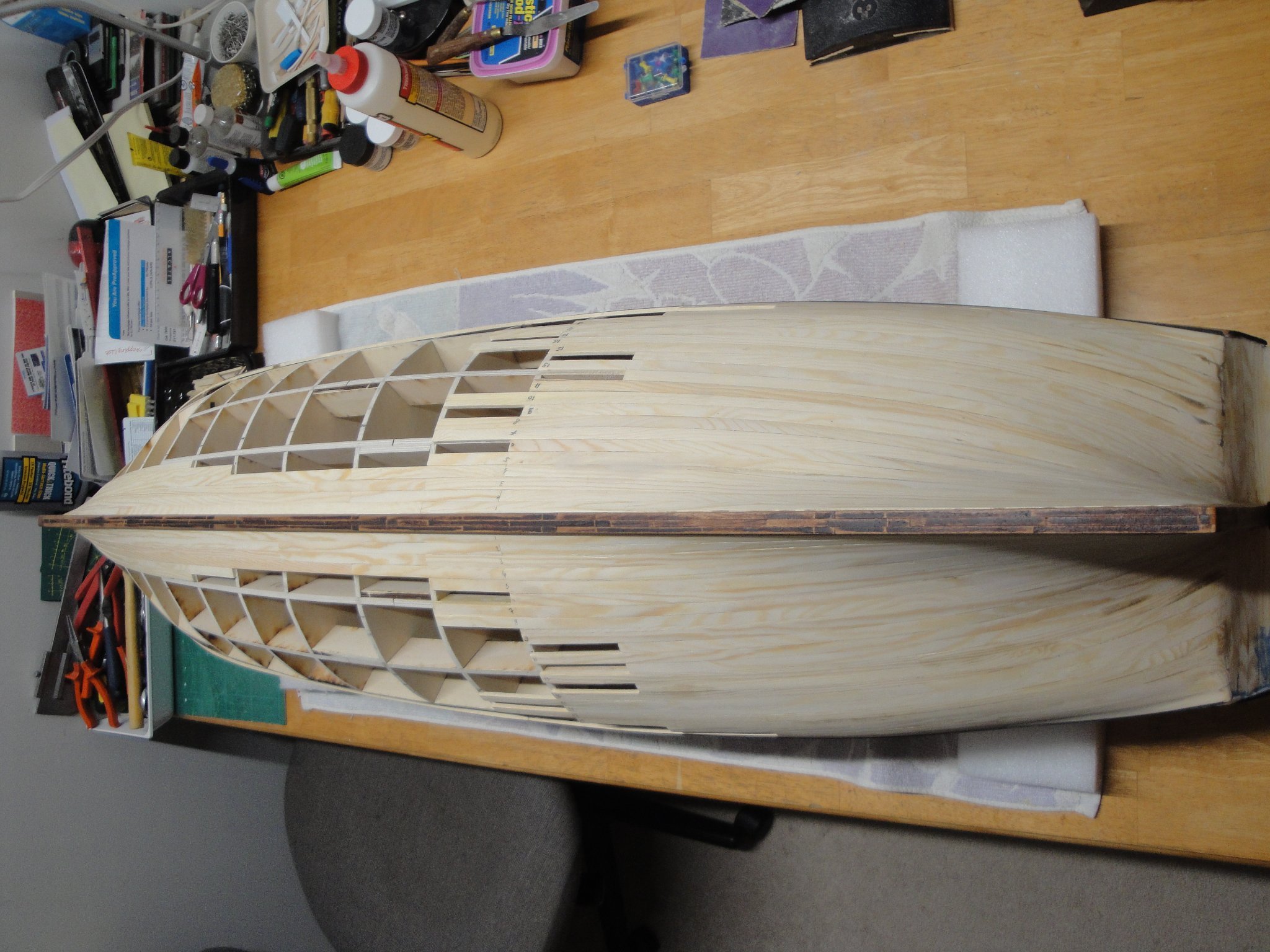
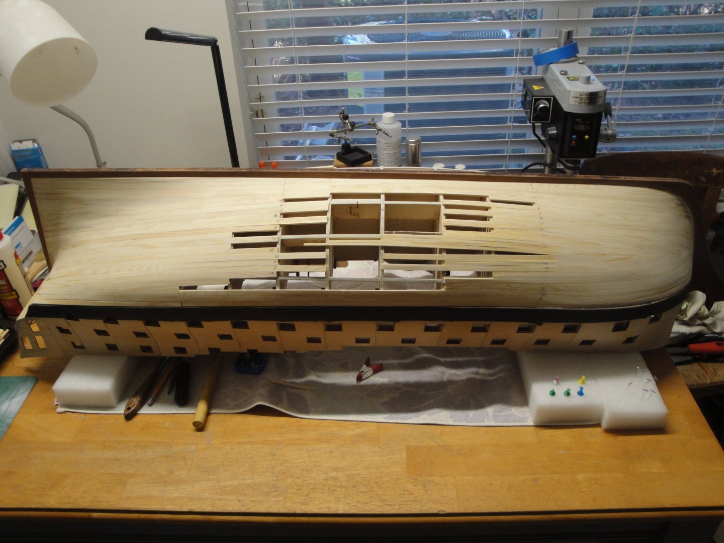
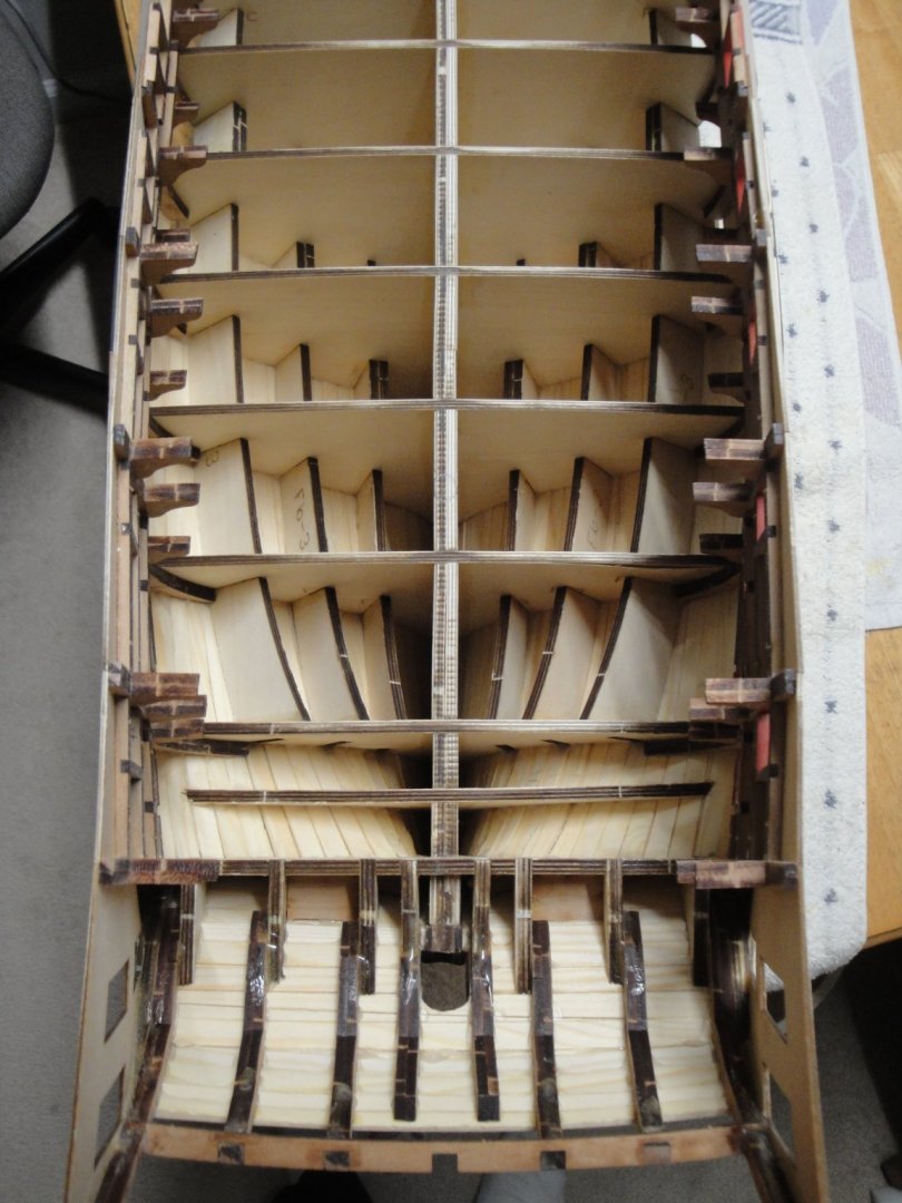
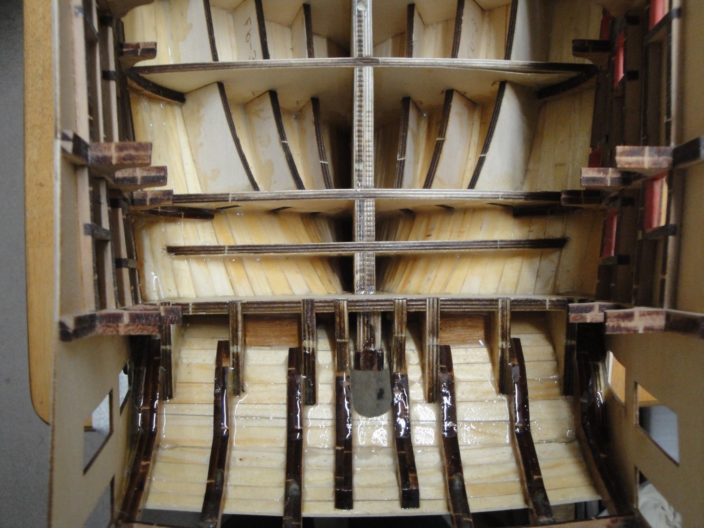
Second quadrant completed. Of course, lots of sanding remains to be done.... but the overall shapes are there: I am leaning very strongly in favor of a coppered hull. Copper tiling has always been a fascination for me (the glittering of the metal...) and since Bellona was tiled later in its existence, it makes sense to try to do it. Besides my planking is far from being presentable as such and will require a second planking in the non-tiled sections (above the water line). I also suspect that the bow is going to be even more difficult to plank than the stern... Therefore, I am learning about the tiling process by reading what the members of this forum have done on their models. The deep blue is the one that matches the best, the English paint used on these period ships. Inside the hull, I am brushing some acrylic resin on the wood, to seal it and increase the bonding strength of the planks to the bulkheads. There is an enormous amount of pressure and tensions taking place and I do not wish the planks to start coming out, in a few months or years. Planking has been done with Thick and Quick Titebond glue (or is it Quick and Thick?) and I trust them to a certain point. The only glue I trust fully is the two components epoxy, slow curing glue. Before brushing the resin.... And after ! I noticed that the lime/poplar wood provided by CAF Model was occasionally splitting. Soaking that wood into resin is probably a good insurance for the long term. Interestingly, no resin seeped through the hull....indicating that it is waterproof. Just for fun, I could not resist trying the various gun deck pieces: And the Upper deck and misen mast: It is getting exciting.... Yves


- 507 replies
-
- 14
-
-
-
Don't feel bad Zack. We all go through these challenges and defeats. It is part of the learning process and the mastering that comes well later.... 🙂 Yves