yvesvidal
-
Posts
3,634 -
Joined
-
Last visited
Content Type
Profiles
Forums
Gallery
Events
Everything posted by yvesvidal
-
 I think your cat was mad for not getting enough attention. I have had many many cats and wood models, and I have never experienced such thing. You need to spend more time with your cat :-) Yves
 -
Rod, Thanks for the compliments. I submitted some pictures of my model to Benjamin but he probably used his own assembly for the article, for various reasons. Yes, I am trying to finish the planking (1st layer) of Bellona and I will then go back to the Corvette and try to complete her. Wood dust and PLA parts do not mix too well..... Yves
- 321 replies
-
- 3
-

-
- Finished
- Flower-class
- (and 1 more)
-
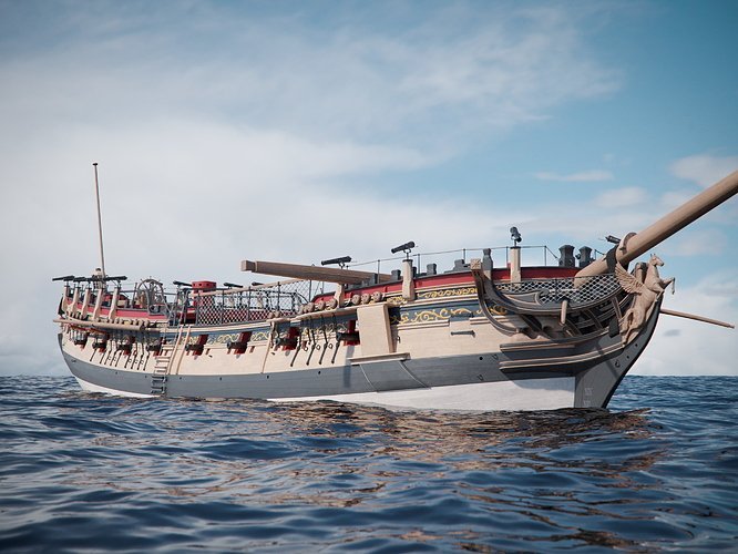
Thank you Allan. Yes, Bellona was coppered later on during its active life on the oceans and I intend to do that on the model as well. You are also correct about the armament that was modified later on and to be totally correct, the guns on the quarter decks would have to be replaced by carronades, which are not included in the kit. There are risks that this model will never be exact, in one form or another. I think I can live with that :-) Yves
-
This is getting really impressive and exciting. Yves
- 454 replies
-
- 3
-
-
- Union Steamship Company
- Stepcraft 840
- (and 3 more)
-
Beautiful Model Bruce. Absolutely outstanding. Happy New Year and many more models. Yves
-
Brian, What a fantastic model. I love the attention to details and the creativity with materials and parts. Your bench is looking great with all these organizing boxes. Yves
-
I love the sand and plants. Very nice touch. Yves
-
Your pictures are not showing up... Yves
-
I am not a supporter of tree nailing but I admire your patience and skill. Yves
-
Excellent Summary of this great kit. I agree completely with your review of the kit and share your enthusiasm about it, even if I did not complete my ECB yet. Yves
-
You will love the Calypso. I built mine 35 years ago and had it navigating on the mediterranean sea, and various lakes in France and America. I still have it and will refurbish it one day. Yves
-
Beautiful work Derek. Happy and Merry Christmas to you as well. Yves
- 345 replies
-
- 2
-

-
-
- Duchess Of Kingston
- Vanguard Models
- (and 1 more)
-
Tamiya acrylic paints have to be diluted with their thinner. I use 50% paint, 50% thinner in the summer time. In the winter, you may want to go more 70% paint and 30% thinner. Otherwise, it will run way too much. But you probably know all the above, already. Yves
-
What a beautiful l ship... and that bow is amazing of perfection. Yves
- 345 replies
-
- 1
-
-
- Duchess Of Kingston
- Vanguard Models
- (and 1 more)
-
well, after the capstan and the wheel, you now need to build the ship that goes around them, also at the 1/16 scale. Yves
-
Giampiero, Will you be keeping the top of the hull black or will you paint it Royal Blue for the background of the friezes, as many models have suggested? Yves
-
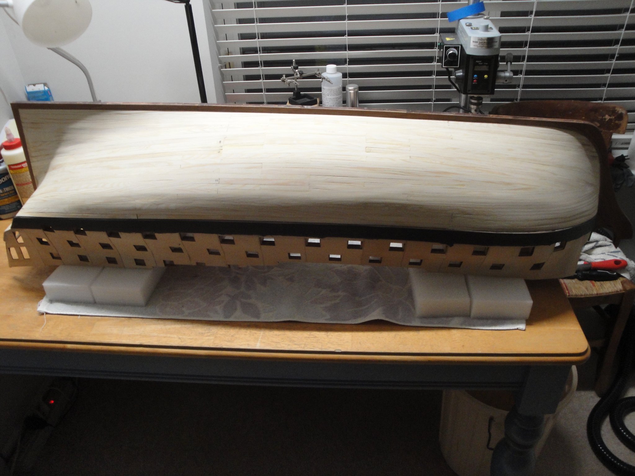
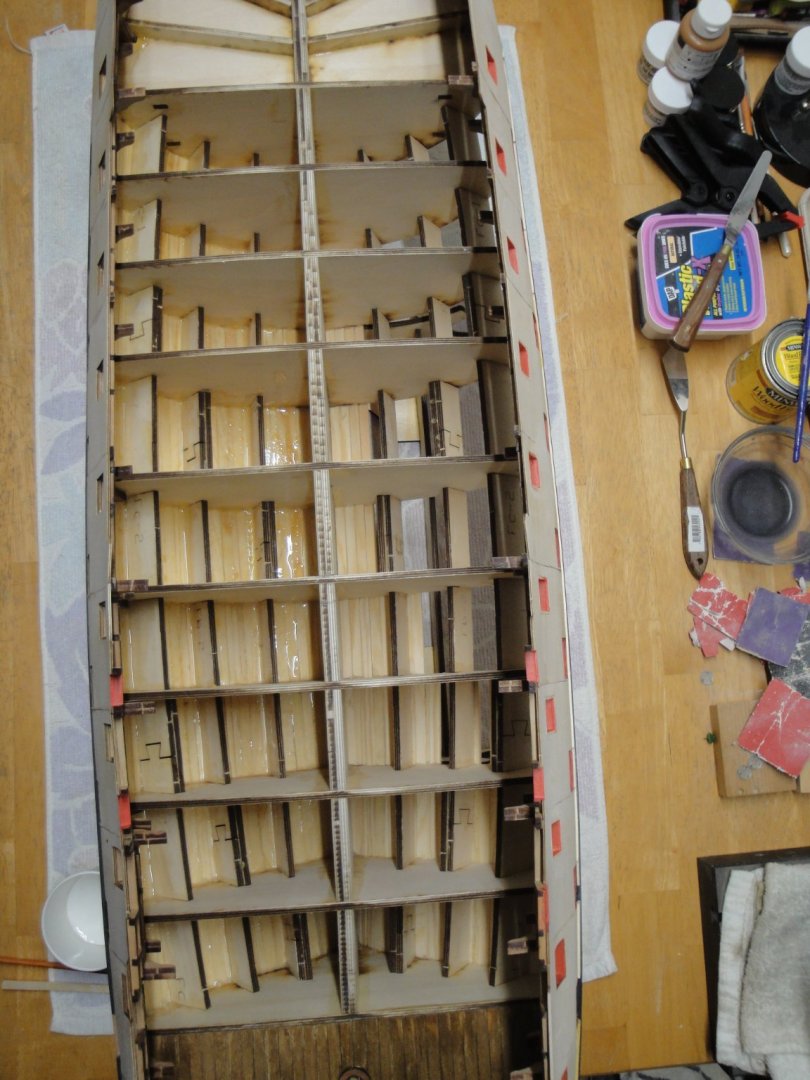
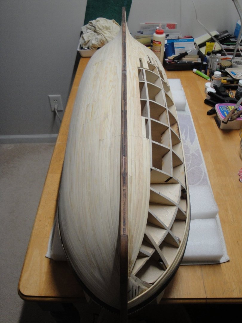
The acrylic resin has been brushed on the inside of the port side: This seals the wood from external agents (humidity mostly) and increases the bonding strength of the wood glue. The resin is permeating the wood fibers and contributing to their resiliency against aging, hygroscopic and temperature changes. It is suggested by CAF and has been used with success by many modelers before. Yves
-
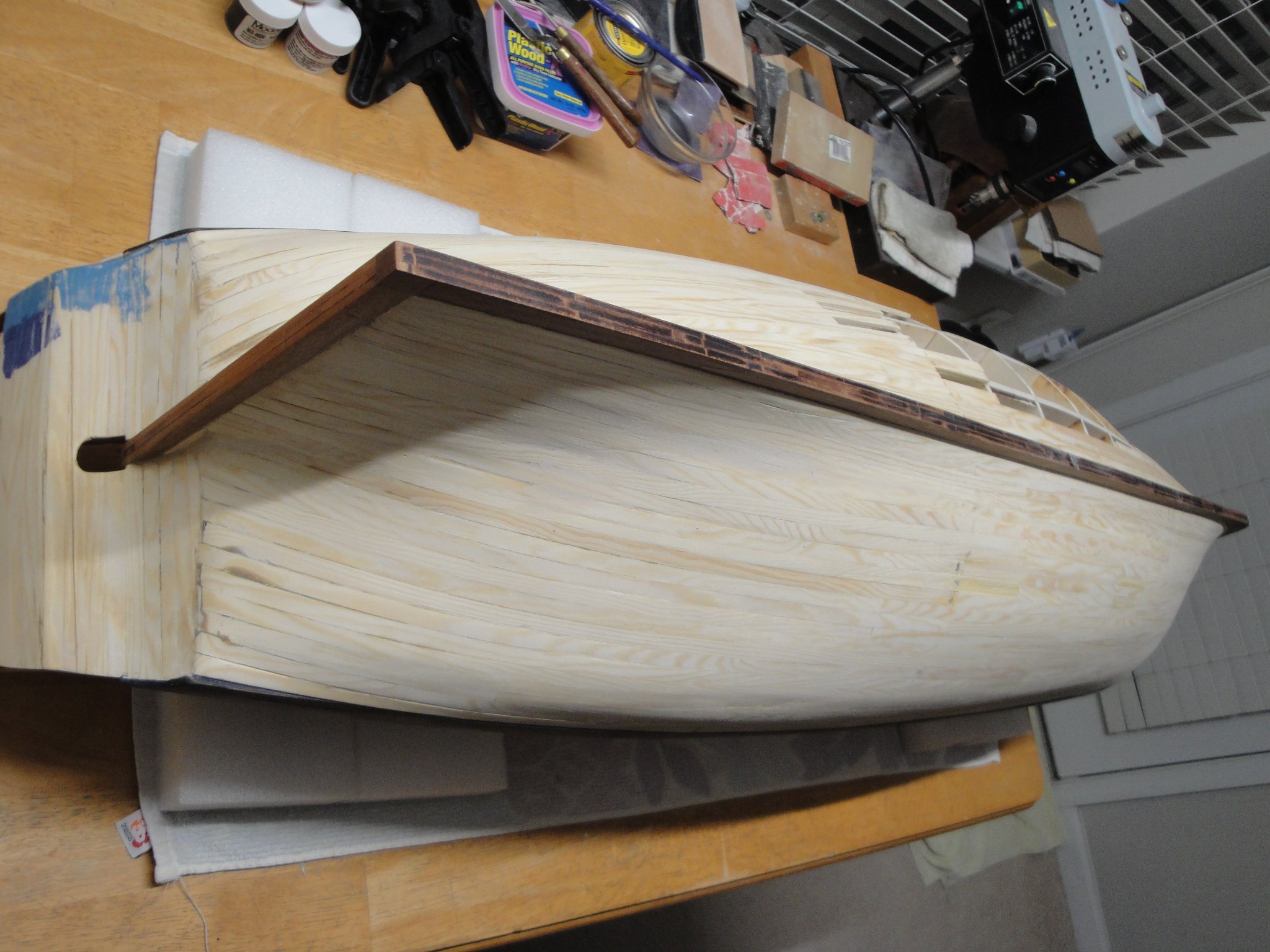
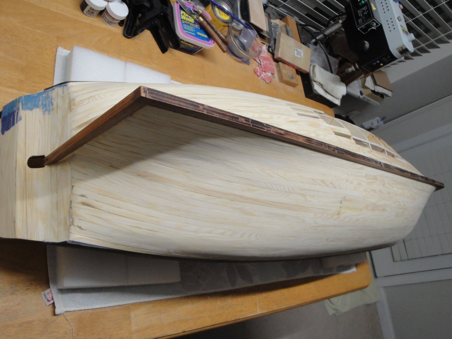
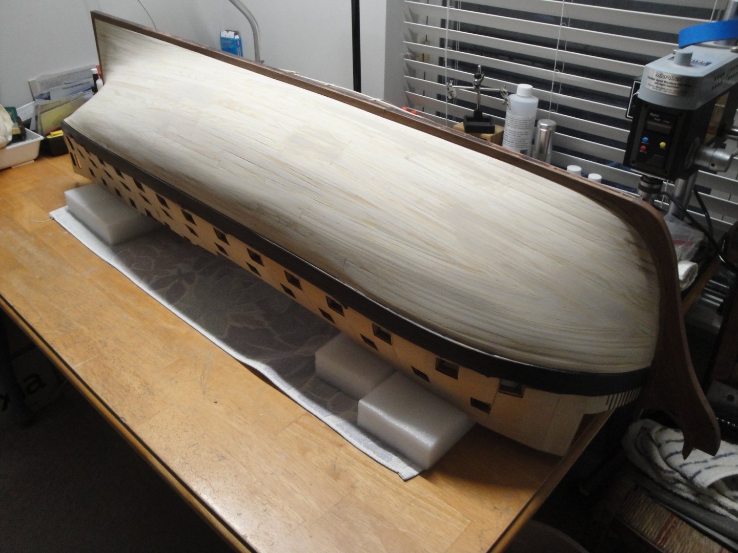
One side done: Now, I have to brush the resin on the inside and do some sanding to make it silky smooth: Yves

- 507 replies
-
- 18
-
-

-
Incredible and beautiful work. I am speechless.... Yves
-
Beautiful woodwork. Yves