yvesvidal
-
Posts
3,634 -
Joined
-
Last visited
Content Type
Profiles
Forums
Gallery
Events
Everything posted by yvesvidal
-
 Thank you Kevin for the drawings of the smoke float and Kevin-the-lubber for this great 3D rendering of the devices. I have made some progress with Meshmixer and know how to move, rotate, resize and cut planes. I will get to these devices to finalize the Corvette. Yves
- 321 replies
-
- 3
-

-
- Finished
- Flower-class
- (and 1 more)
-
Great use of the tub !!! 🙂 The boat is doing well and seems to be correctly ballasted. Yves
-
Beautiful model. Congratulations. Yves
-
Thank you Kevin. Yes, I wished these would be available in the kit. I am no expert with 3D modelling (actually completely ignorant...) and thus I would have to procure these Smoke Floats from another source. Yves
- 321 replies
-
- 5
-
-
- Finished
- Flower-class
- (and 1 more)
-
Superb results. Your work is amazing. Yves
-
That must be nerve wracking.... Have you thought about using Acrylic glue such as Gator Glue? It gives you plenty of time to position the parts. You can always re-enforce with CA glue later on. Yves
-
Not really. Sackville is a completely different beast and much more modern vessel. I have studied the pictures of Sackville and I have to say that I am really impressed by how the Canadian museum association have restored that vessel. In retrospect, building the Sackville instead of the Snowberry would have been a lot easier. However, the virtual kit does not have a lot of parts that can be found on the Sackville. Yves
- 321 replies
-
- 5
-
-
- Finished
- Flower-class
- (and 1 more)
-
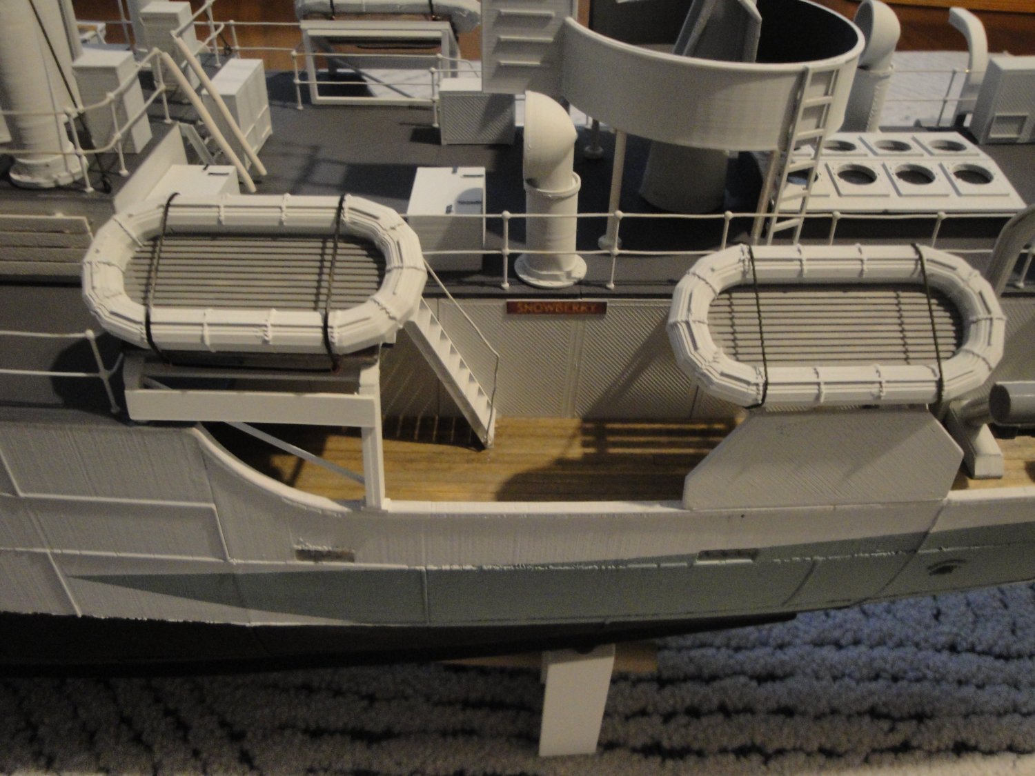
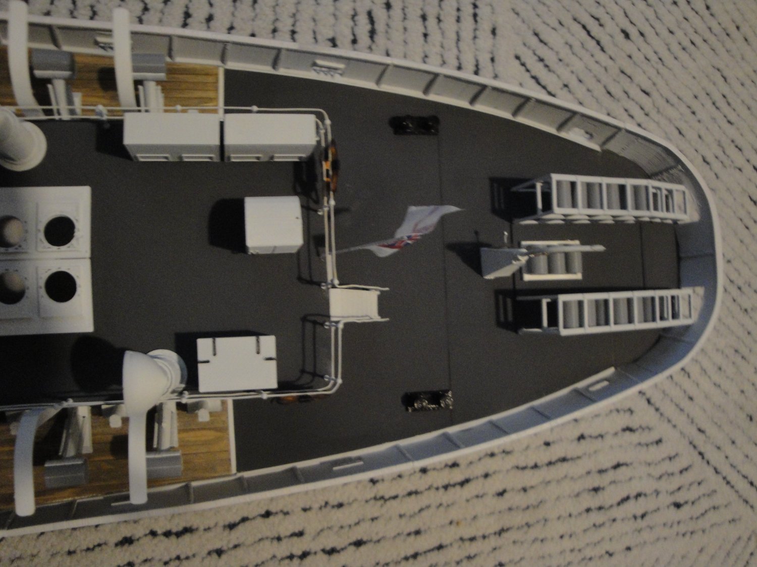
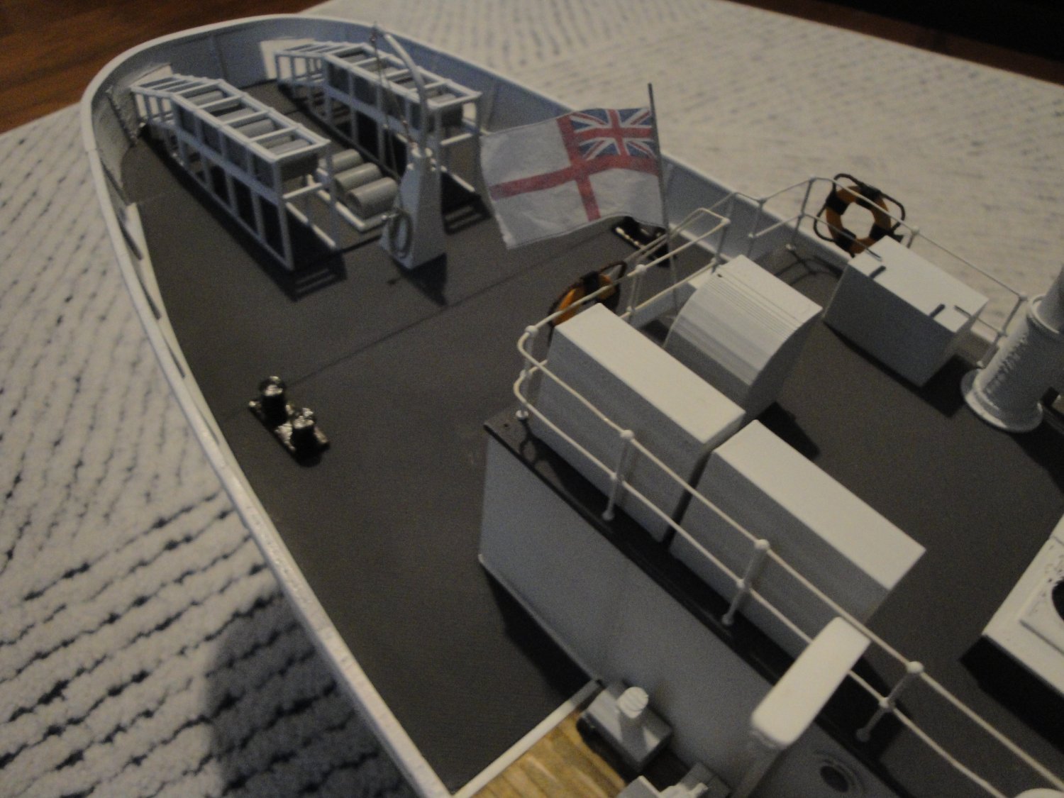
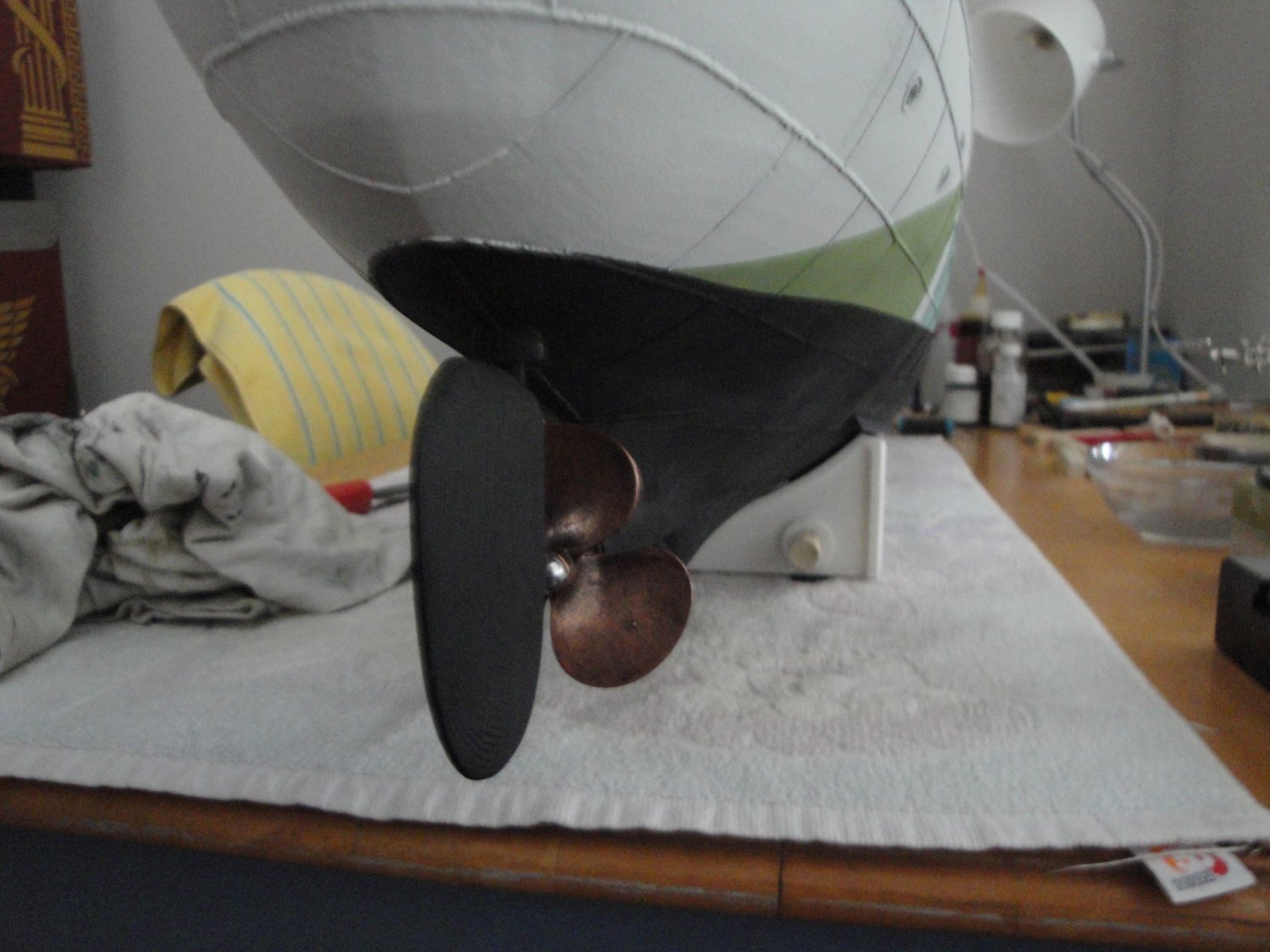
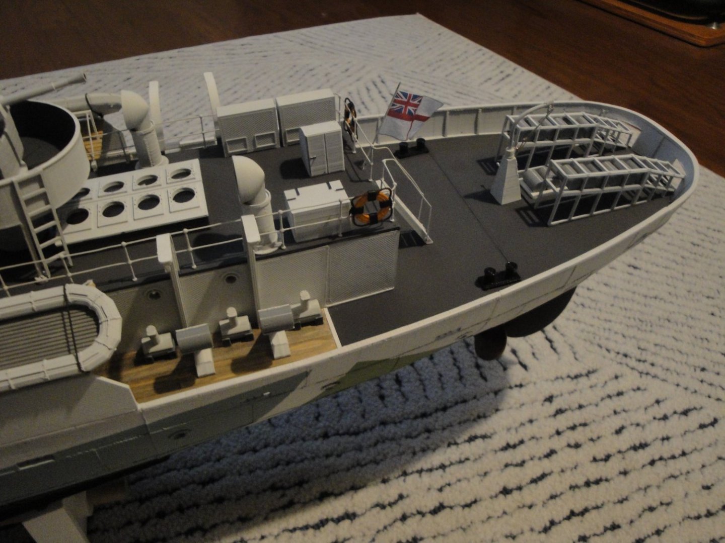
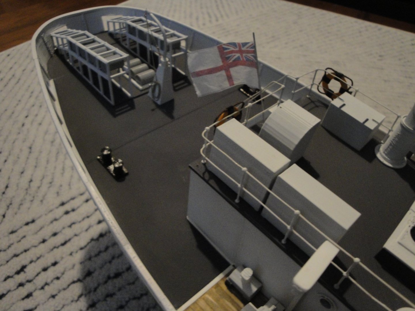
We are getting very close to the end of this project as far as we can ever finish a ship model, especially when using a large scale such as 1/48th. The Module #6 (the rear deck) is almost complete, with its depth charges, chutes and ejectors: I understand that for some modelers, this rear deck seems a little bit empty and I completely agree with that opinion. I wish the kit provided the famous "Smoke Float Canisters" which are usually sitting on top of the depth charge chutes. I tried to study a few pictures of the stern of Snowberry, but could not get much in term of details or equipment. Most of the pictures I have seen are crowded with sailors, making it difficult to see what is installed on the deck. I should definitely place some ropes, laying on the deck.... A view of the rudder: The flag is made with silk paper printed on a color laser printer. This technique has been described by Chuck, a few times and provides a nice rendering of a "floating in the wind" ensign. I will try to post more overall pictures of the model, to conclude this build log. Yves


- 321 replies
-
- 14
-
-
- Finished
- Flower-class
- (and 1 more)
-
Superb diorama. The sea is spectacular and you captured very well the color of the oriental seas. Yves
- 179 replies
-
- 4
-

-
-
- hatsuzakura
- pit road
- (and 2 more)
-
What a marvel !!! Your work is so meticulous and precise. I love it. Yves
- 140 replies
-
- 2
-
-
- benjamin w latham
- model shipways
- (and 1 more)
-
I missed your second post, sorry. Obviously, you are now mastering the technique. It does make a big difference and your results are excellent. The residual stuff around the "140" decals can be gently removed with lukewarm water and a Q-tip, delicately. Yves
-
Please experiment with the chemicals on another surface first. You know that decals have to go first on a glossy surface, or as glossy as you can get it. Then use the Microscale SOL on the surface, place the decals and then delicately add more of the Micro-SOL stuff. Then do not touch any more, no matter how the decals look. Be patient. Once dry, you can re-apply the chemical again, as many times as you want. Bubbles can be punctured with a needle and Micro-sol can be applied on top again. Experiment. Good luck. Yves
- 293 replies
-
- 10
-
-
Well, flux is usually what will steer the solder, especially if you use it sparingly. Yves
-
I love the shapes of that vessel. Such elegance and such panache !! Please, keep at it. Yves
-
Good catch and a nice time saver !!! Yves
-
Beautiful model. Billing Boats would be proud of you. I cannot wait to see pictures of the Colin Archer sailing on the water. Yves
-
To conclude this beautiful thread about some Fiat legendary cars: Yves
-
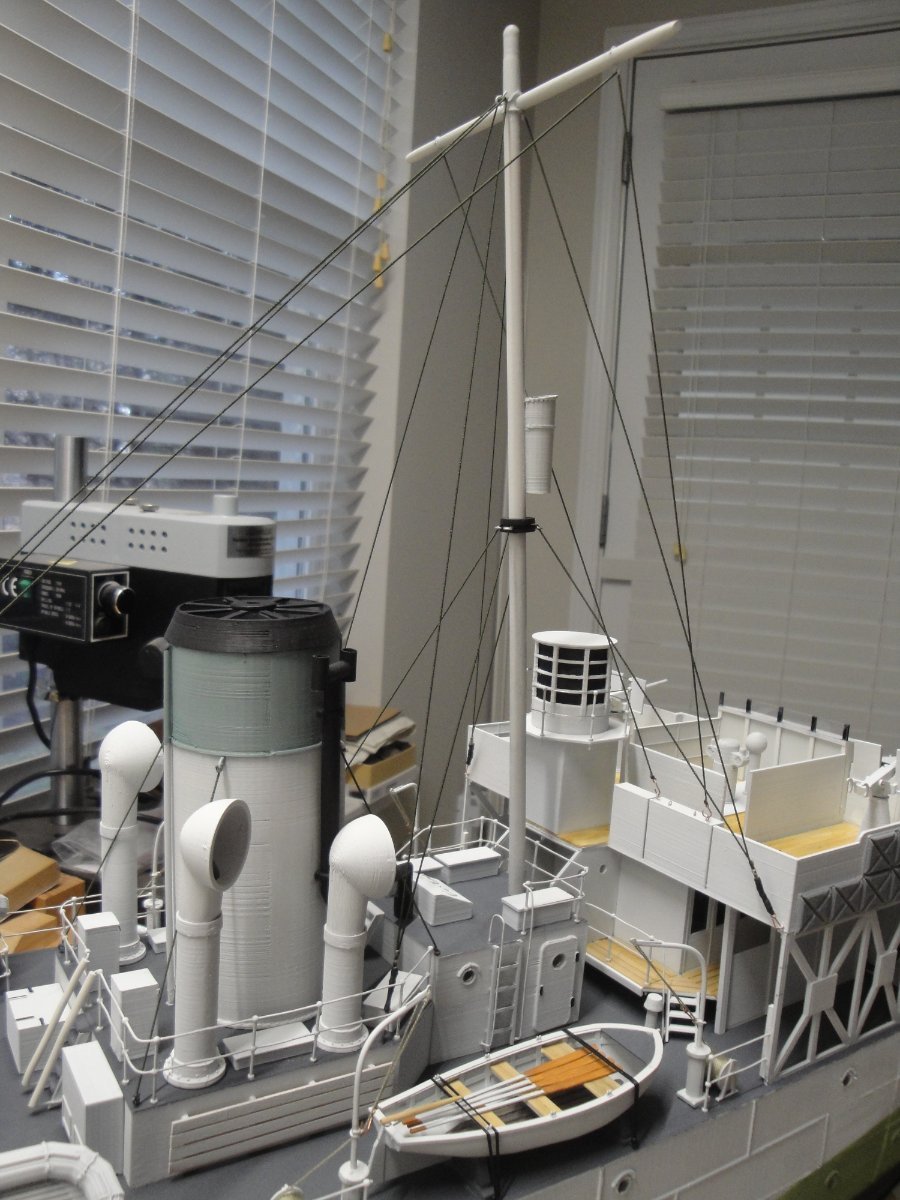
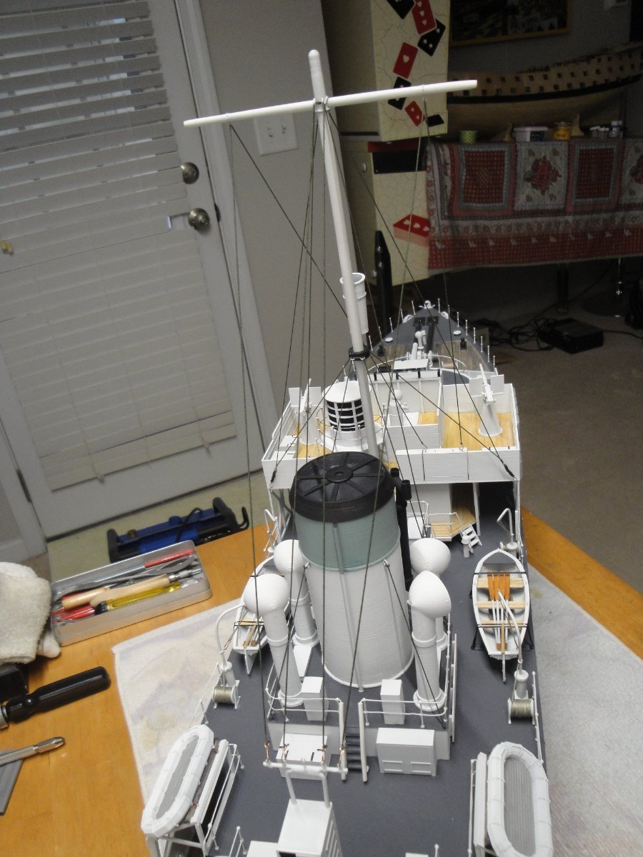
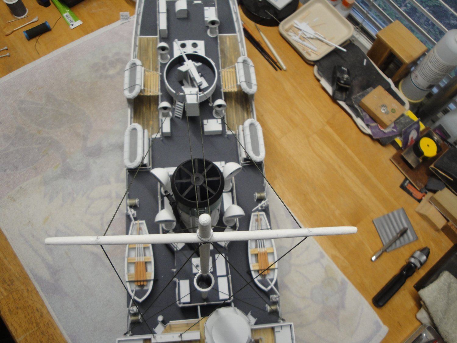
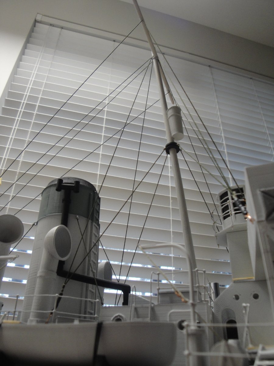
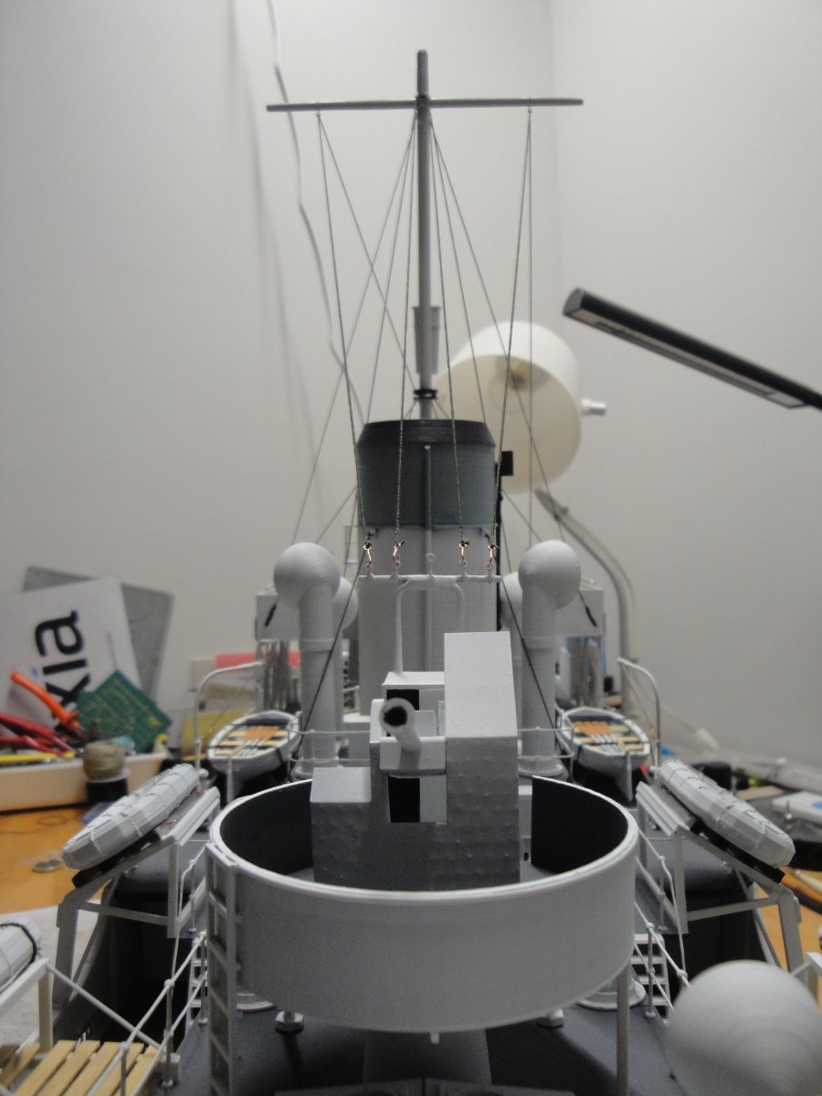
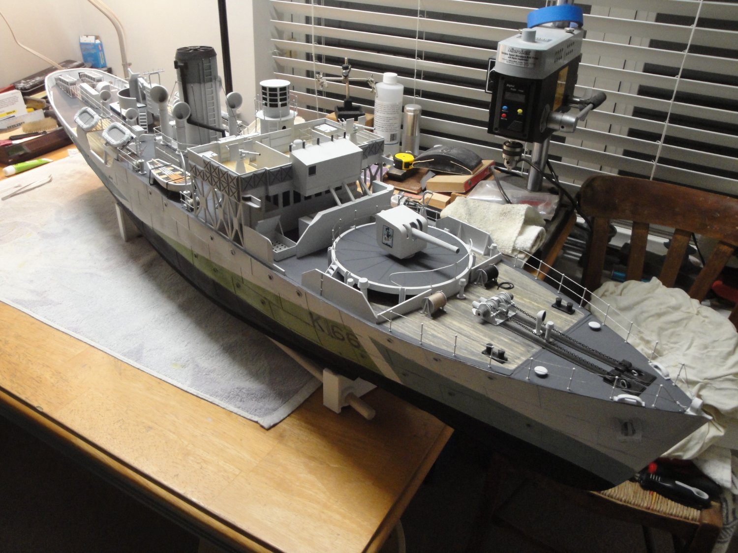
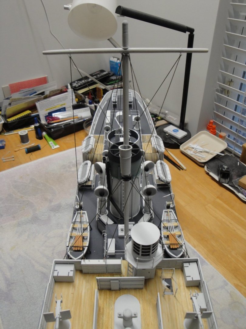
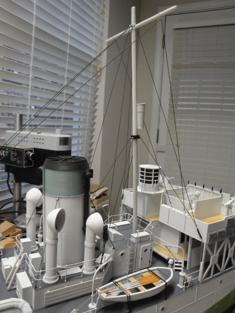
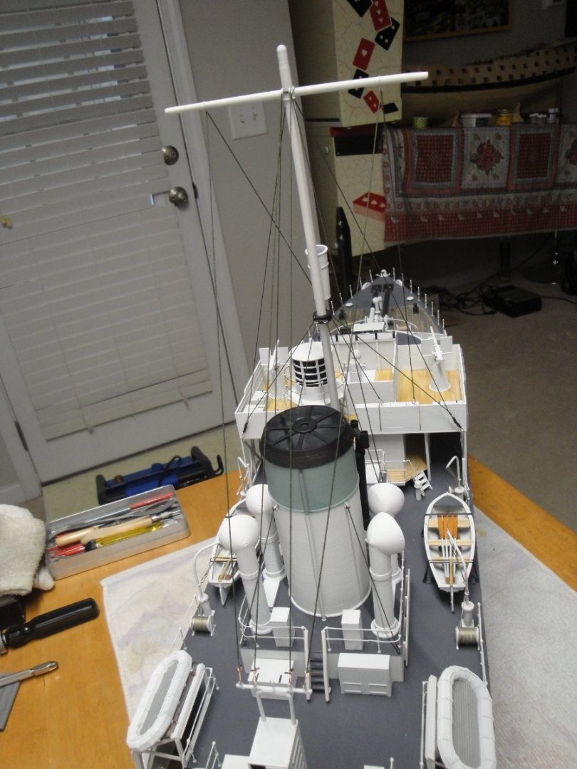
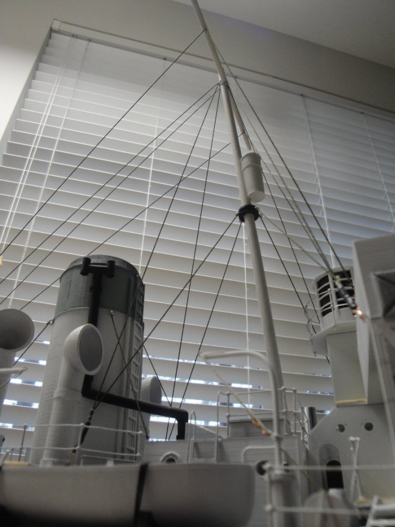
Mast and rigging are pretty much completed. This is a simplified rigging for multiple reasons: I have very little information on how the Snowberry was rigged. Each Corvette was different and the archive pictures are not sharp enough to really distinguish how the rigging was done. With this virtual kit, I am more interested in giving an overall and realistic appearance rather than a perfectly and precise arrangement. Rigging can be improved later on by adding more lines, especially around the flag bins. All the lines are made with elastic thread of 0.3 mm, knotted and glued. I like using that material as it gets under tension very easily and will withstand some mishaps. The entire mast and rigging can be removed if the model needs to be transported. The mast is made of wooden dowels. I did not use the masts provided in the kit as printing such round and long parts is not very pretty, with PLA. Besides, the wood is stronger and a lot straighter. An overall view of the model. The last Module to be completed is Module #6, stern and depth charges. Yves

- 321 replies
-
- 12
-
-

-
- Finished
- Flower-class
- (and 1 more)
-
From what I recall, the Mefistofele has a complete and working engine with moving pistons and a real crankshaft. I saw a model finished once, in a European show and was amazed by what these artists (like you...) can do. These PROTAR kits are almost like assembling the real car, from a mechanical perspective. Yves
-
Fantastic work. For a first time, this is amazing. I hope you tackle the Mefistofele as well and perhaps the Bugatti when it comes out. Yves
-
It will be interesting to follow your Build, as I am building the same ship two times as big. Yves
-
Those judges can be silly sometimes and confuse weathering and actual rendering with sloppiness. Yves
- 454 replies
-
- 3
-
-
- Union Steamship Company
- Stepcraft 840
- (and 3 more)
-
Beautiful planking. Very well done. Yves
-
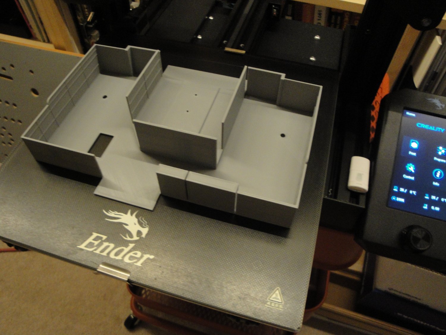
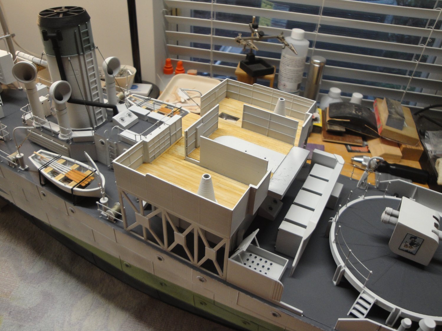
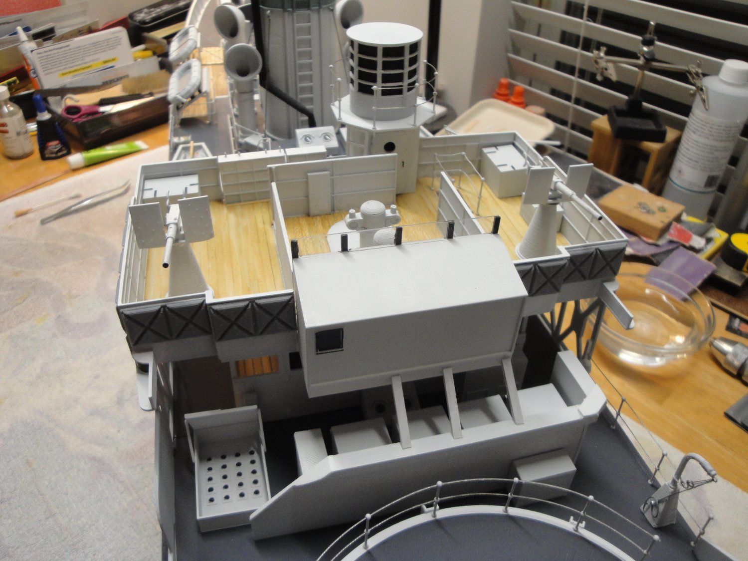
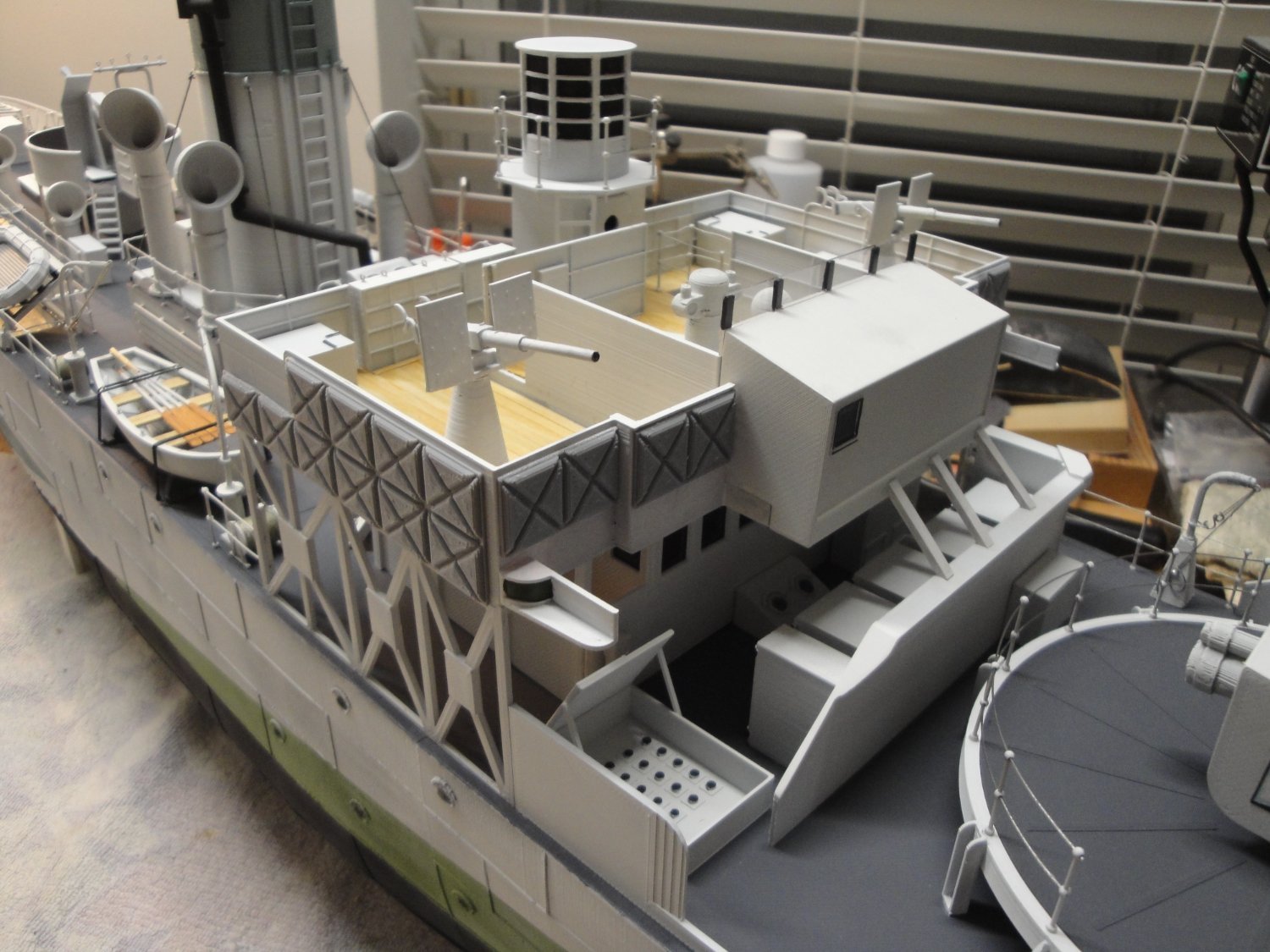
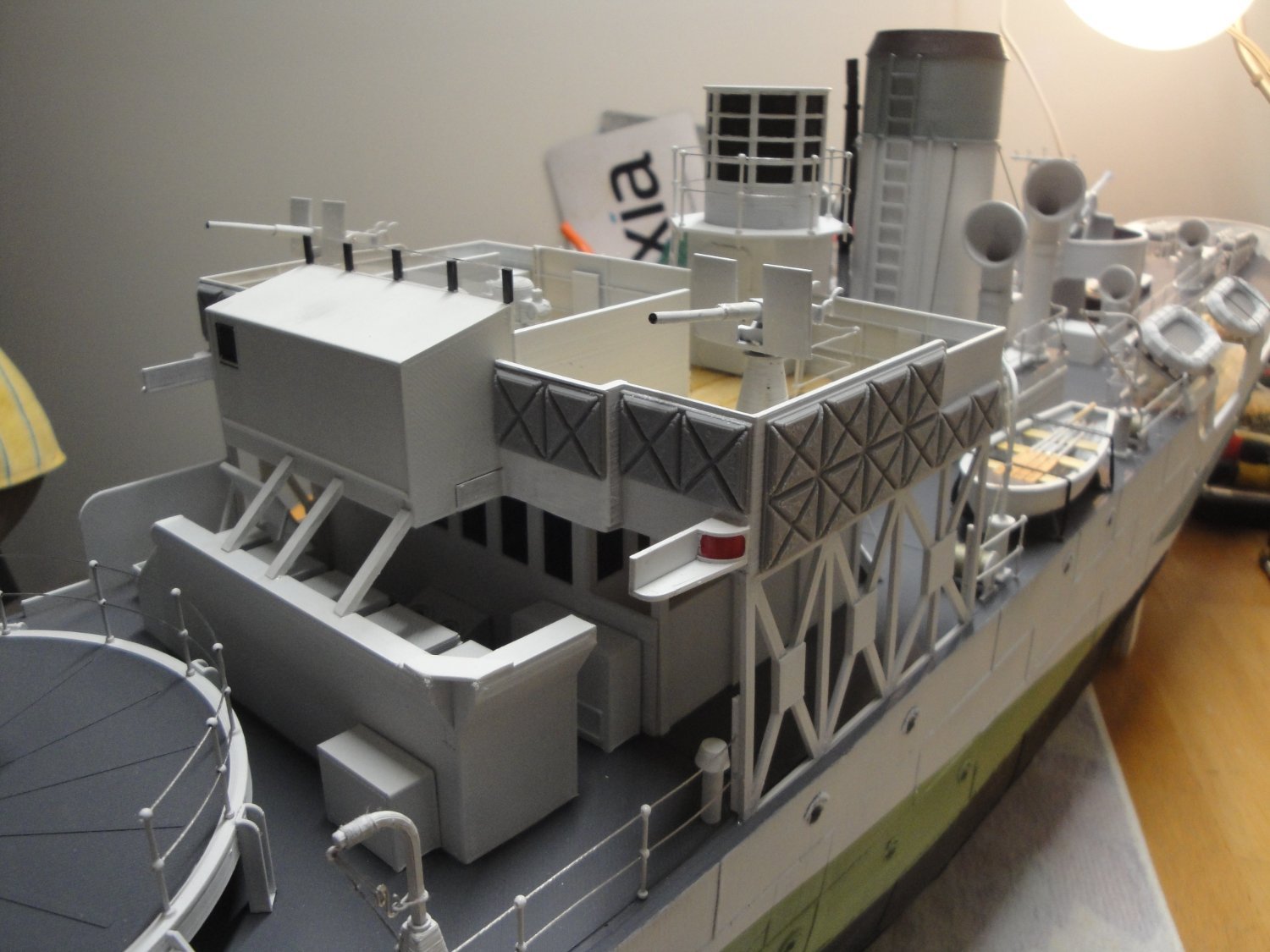
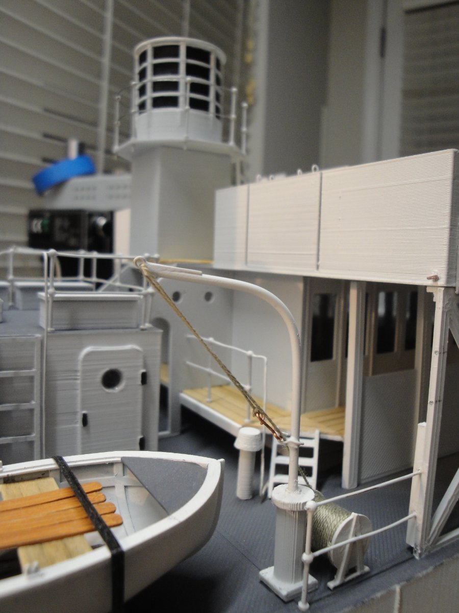
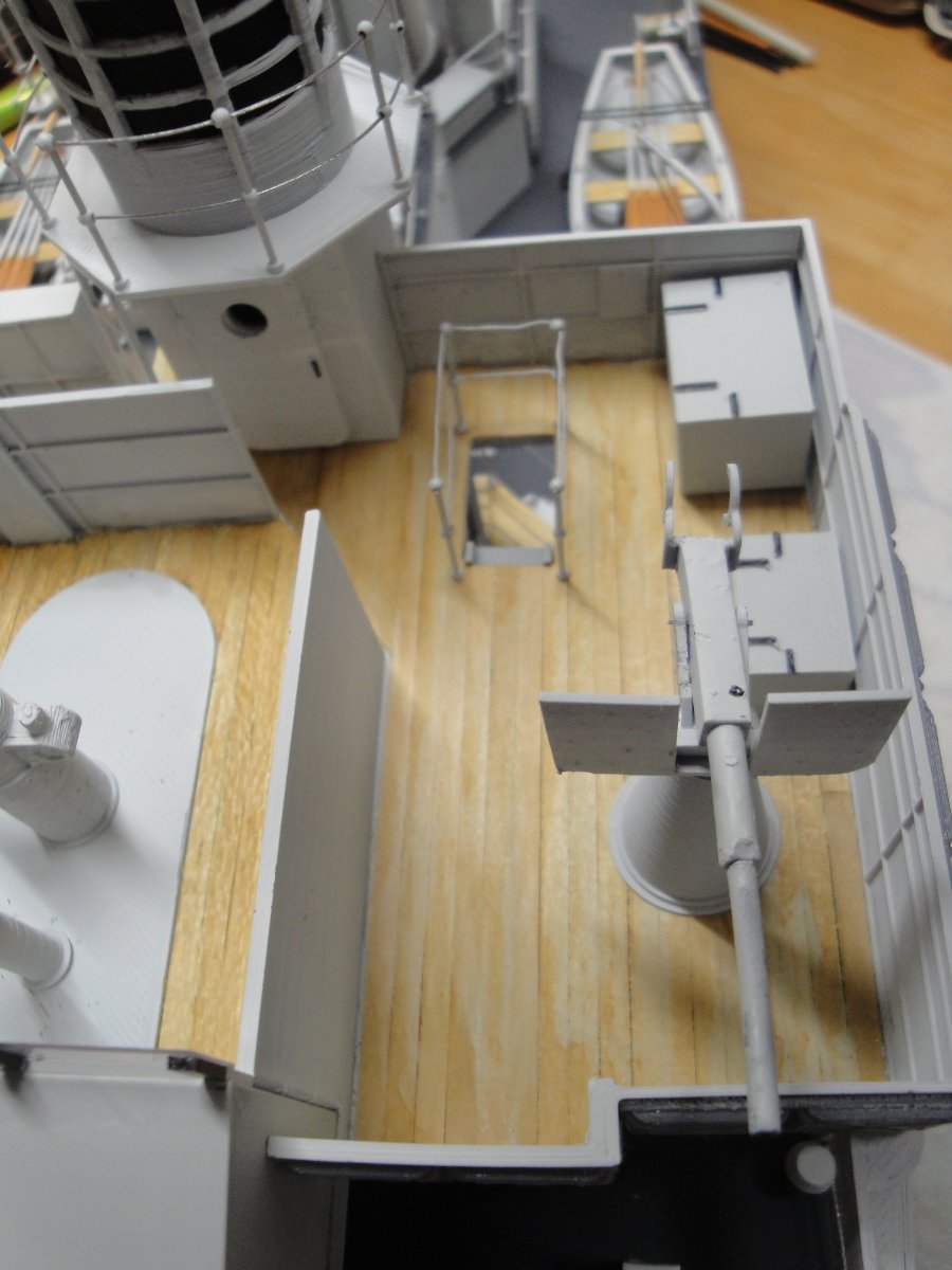
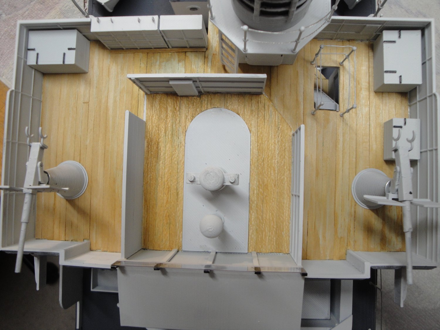
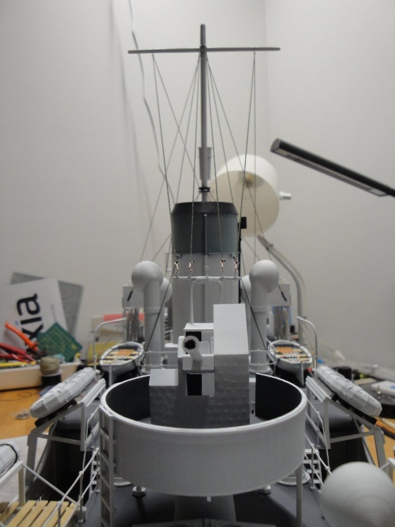
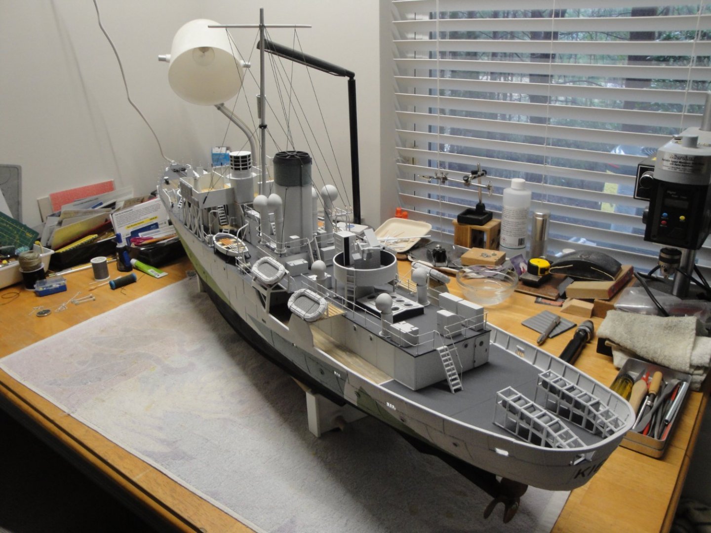
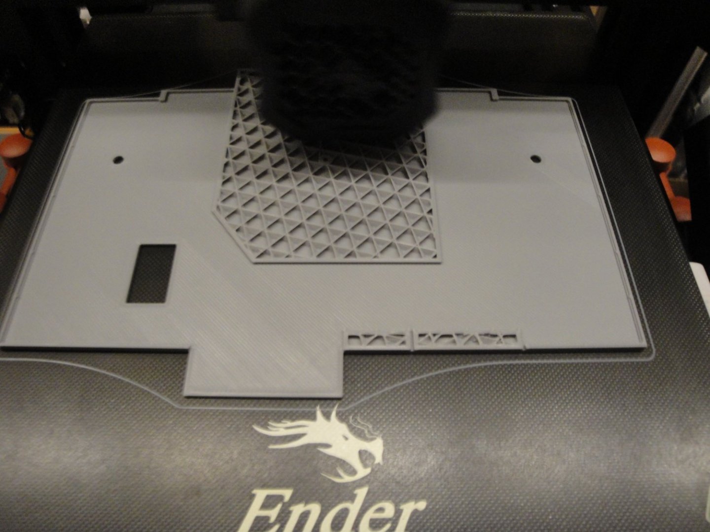
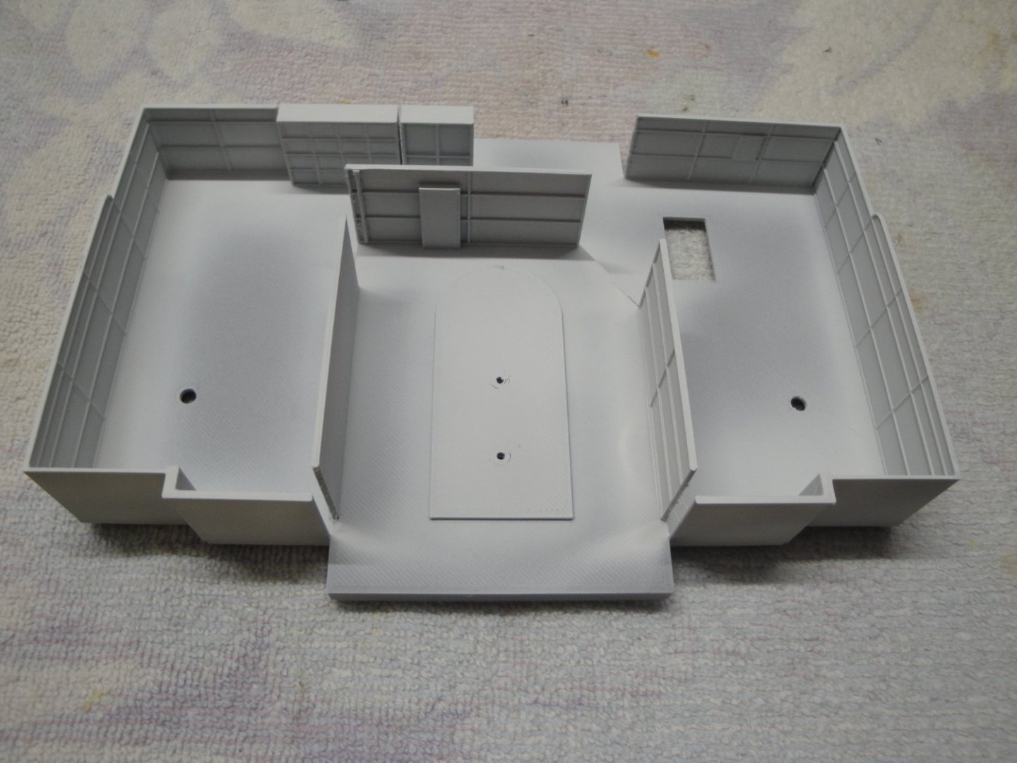
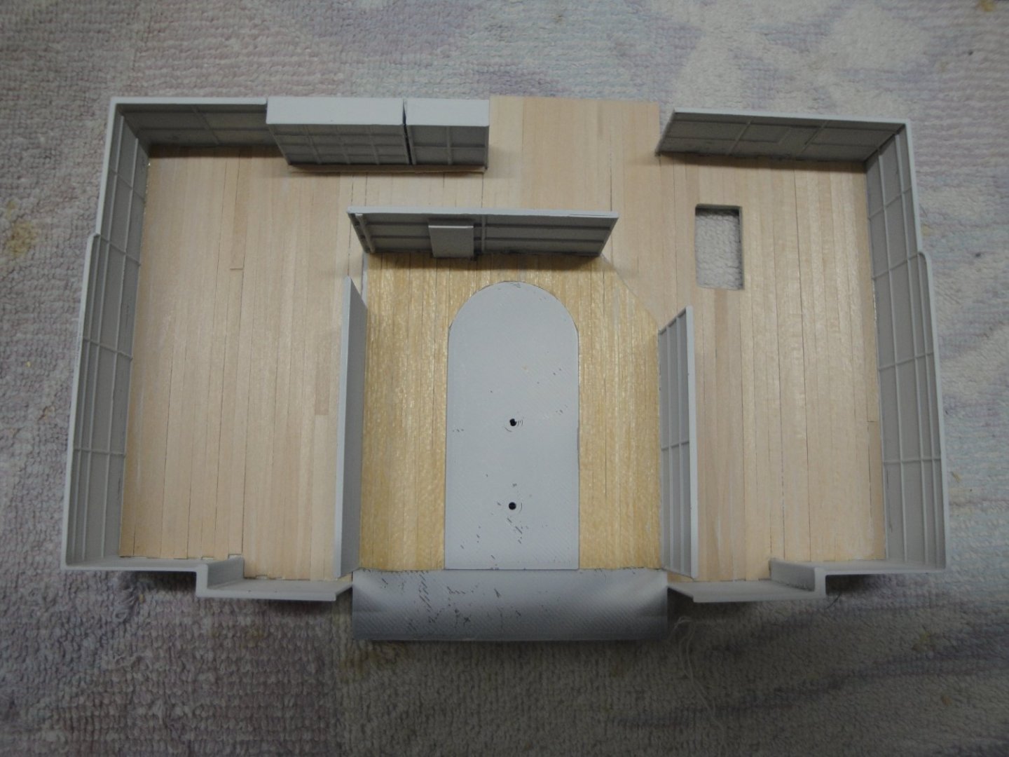
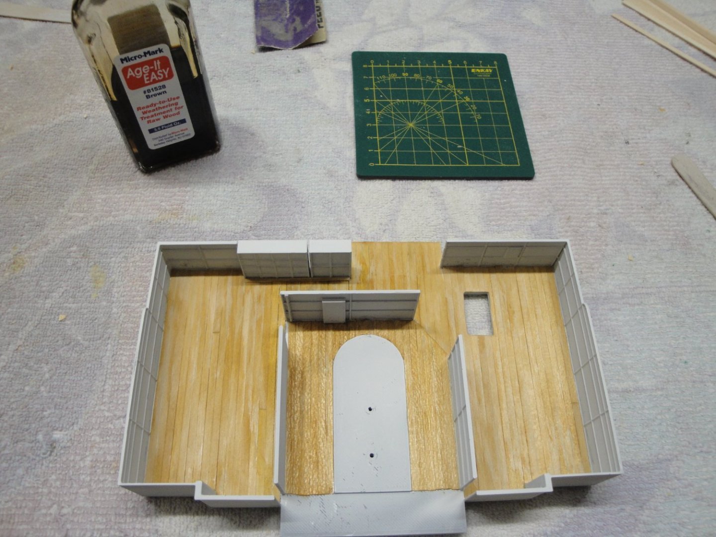
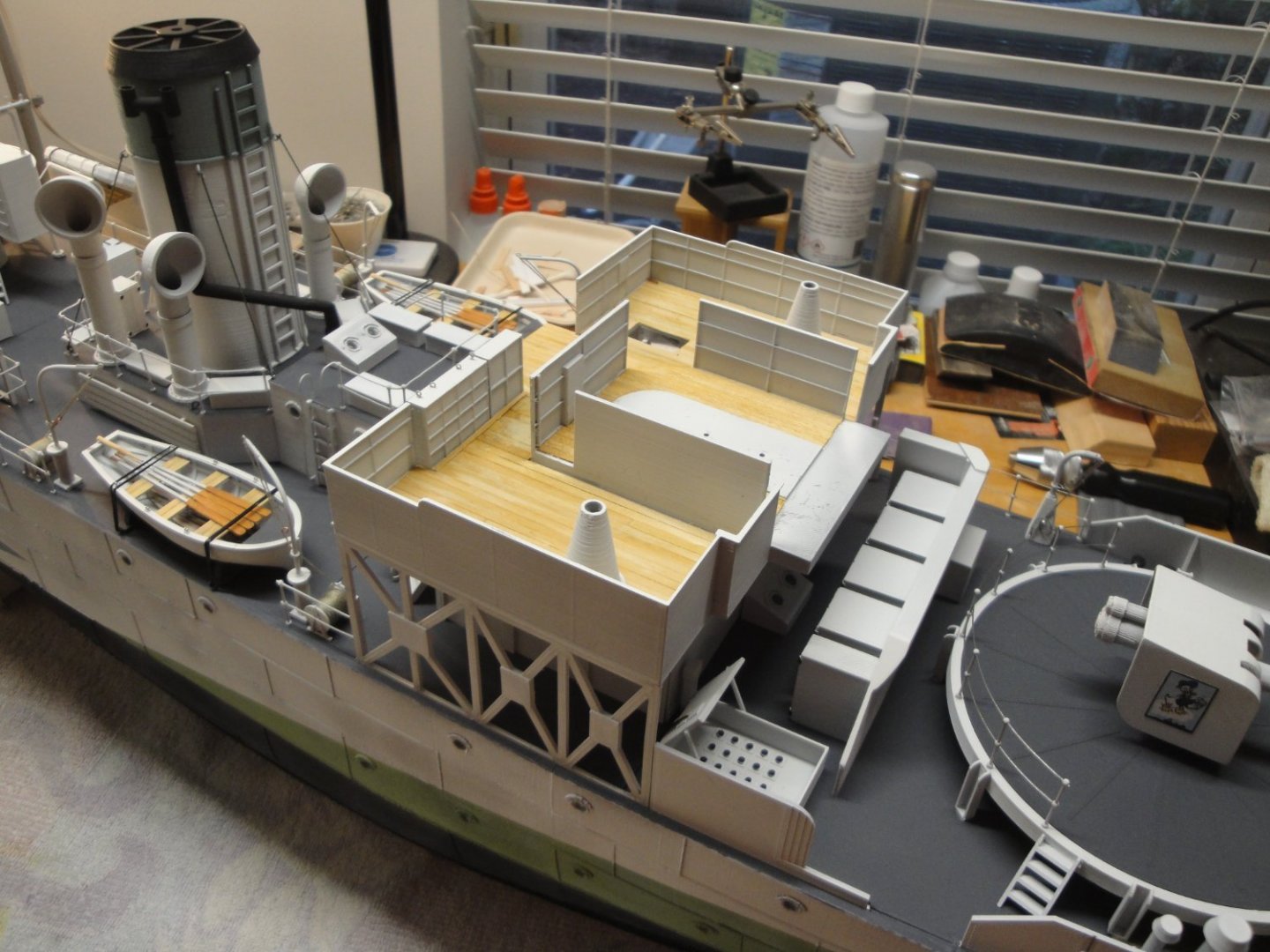
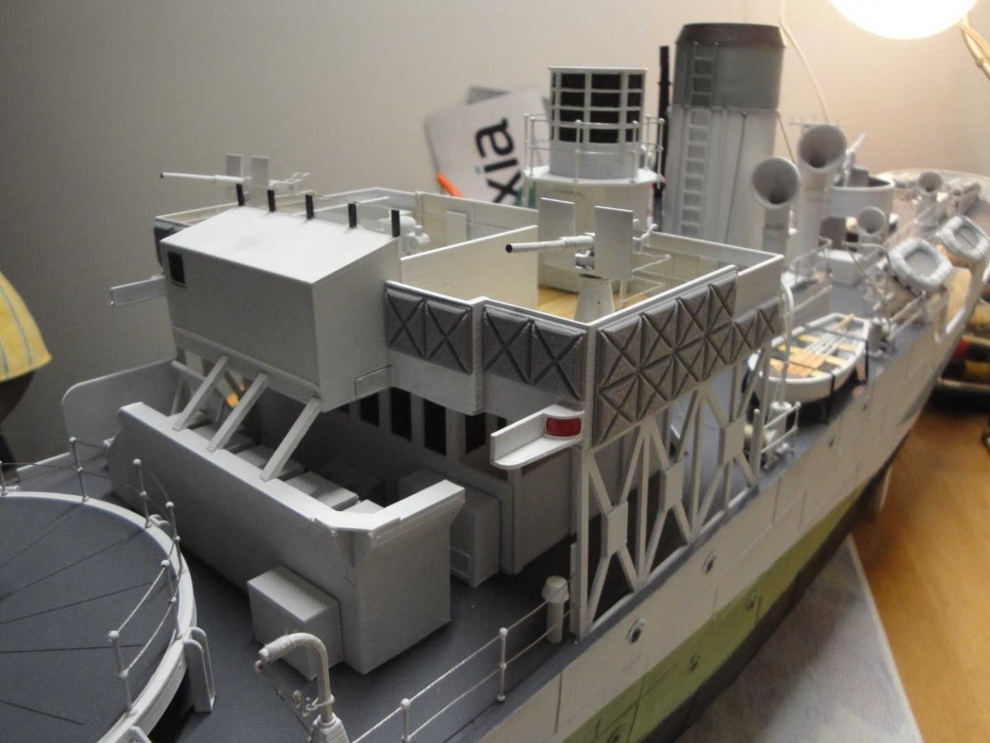
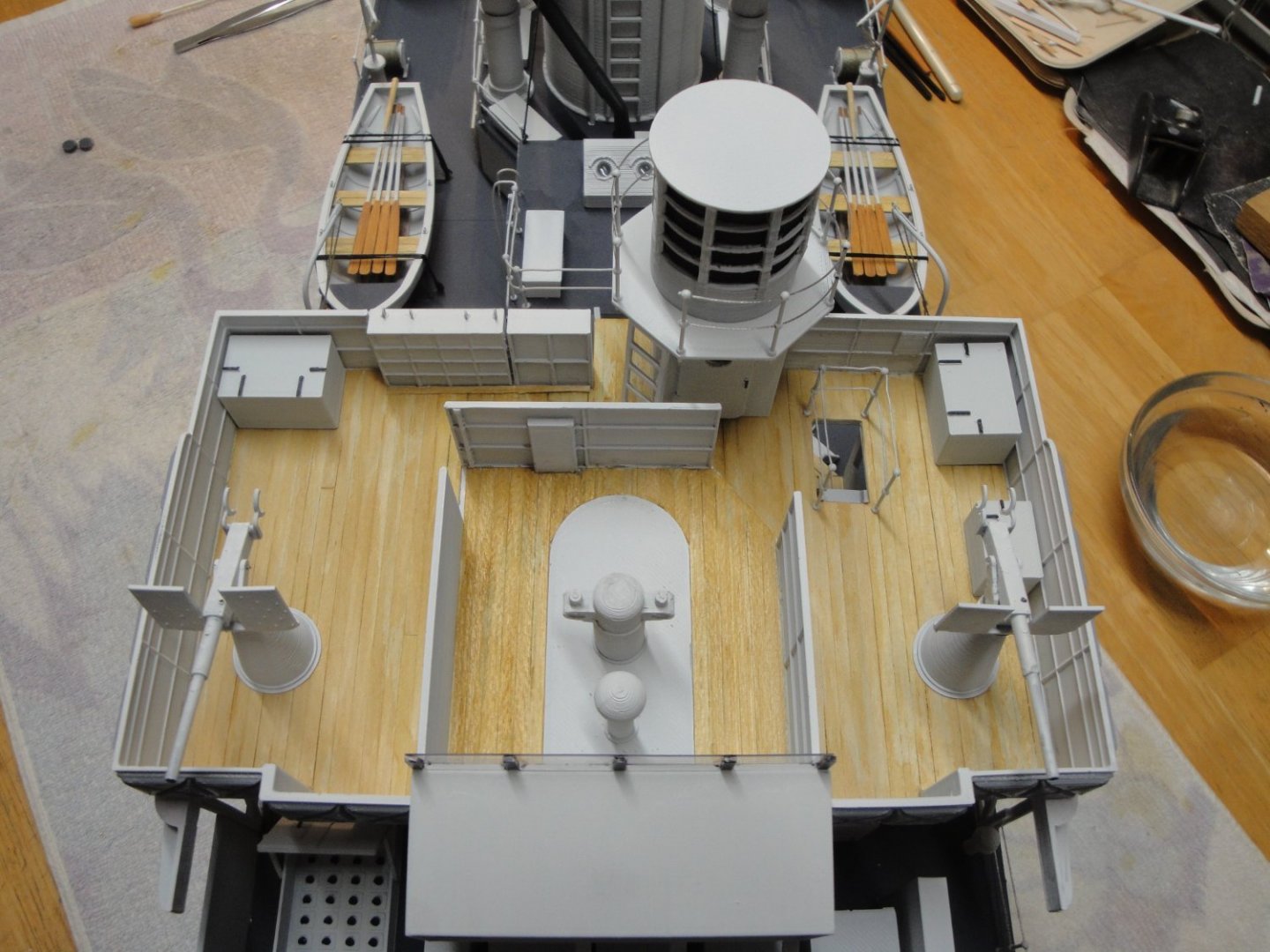
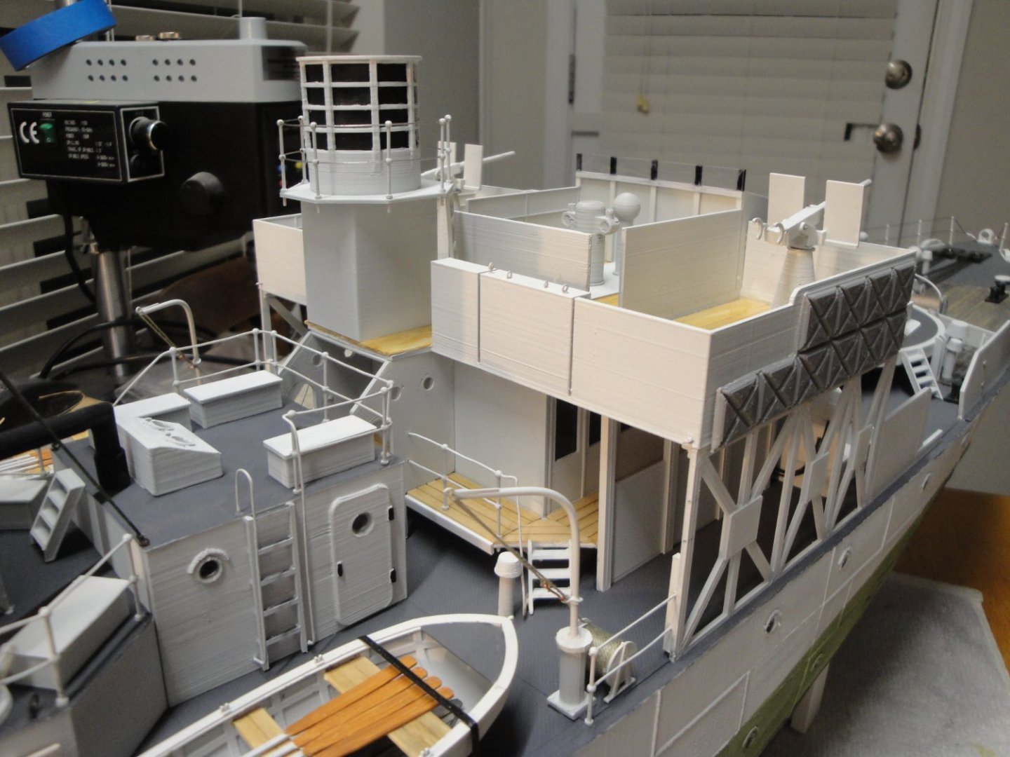
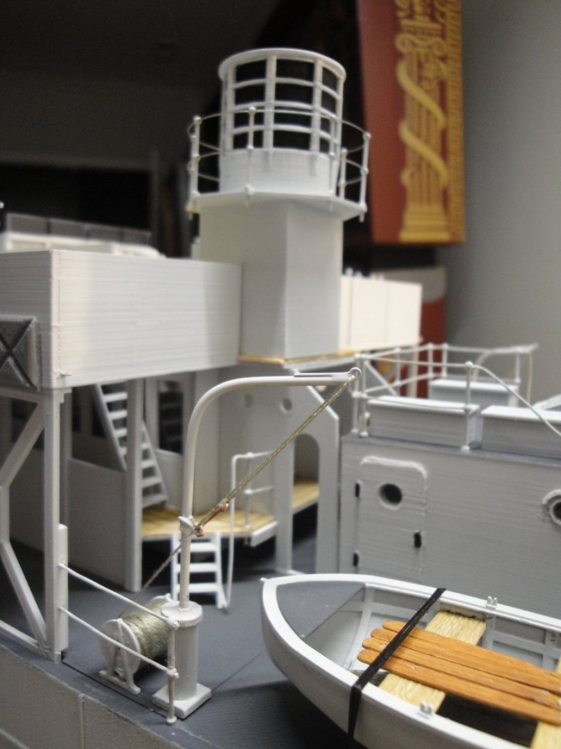
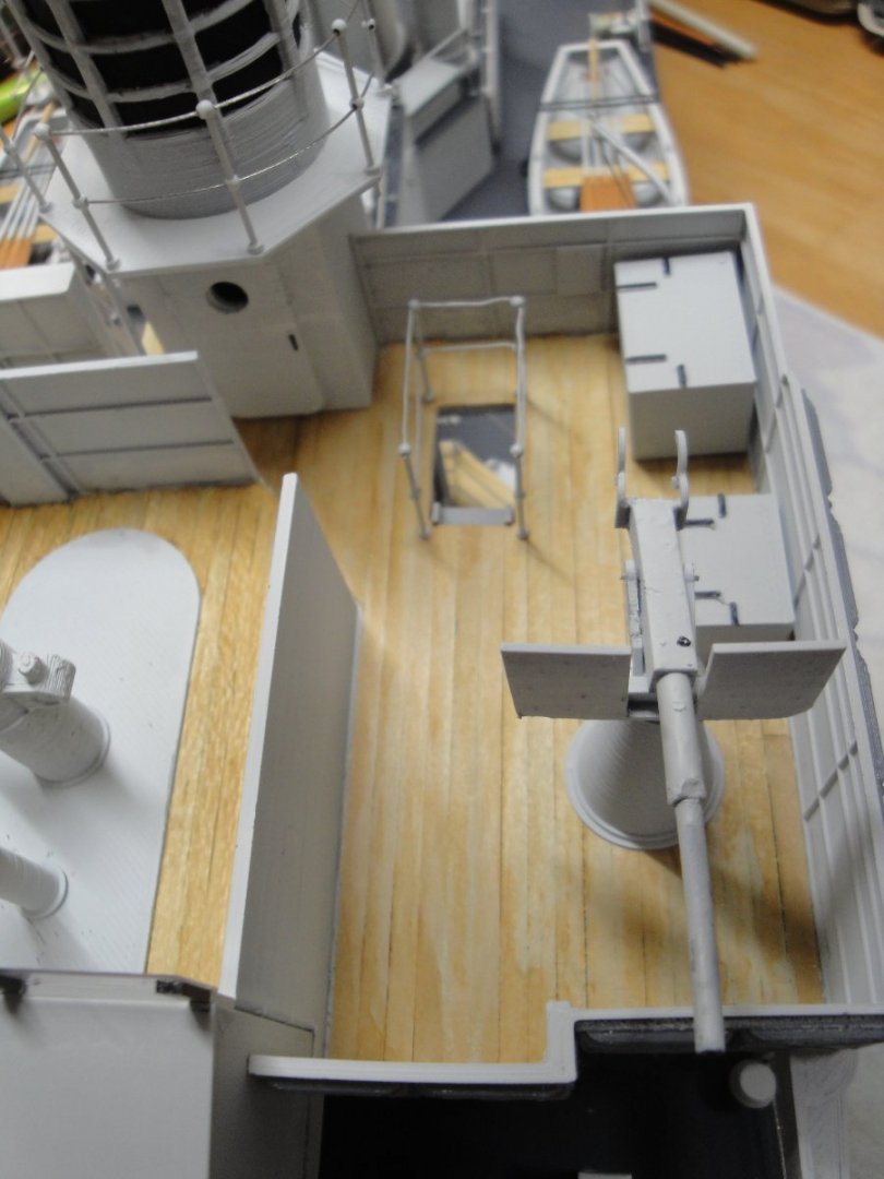
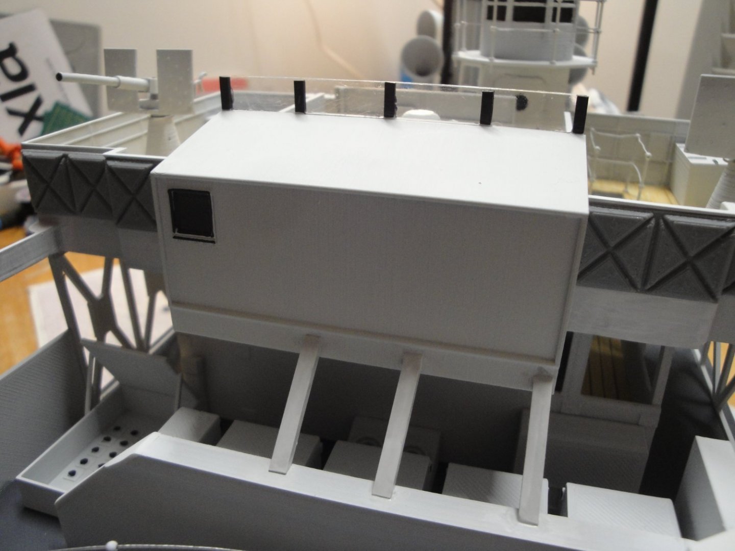
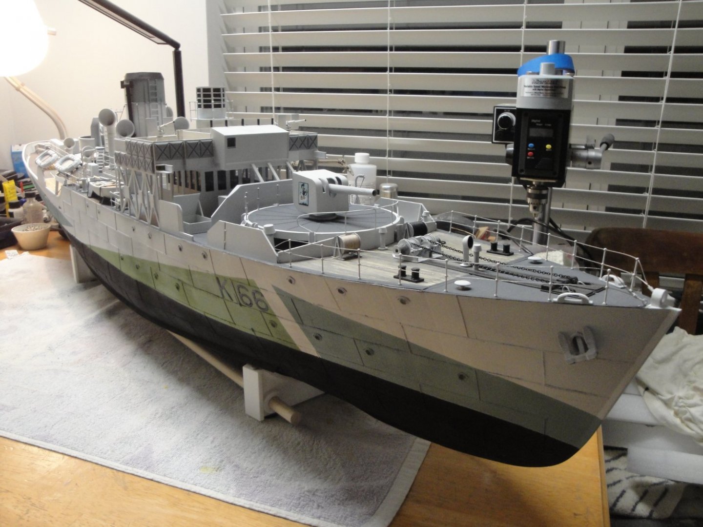
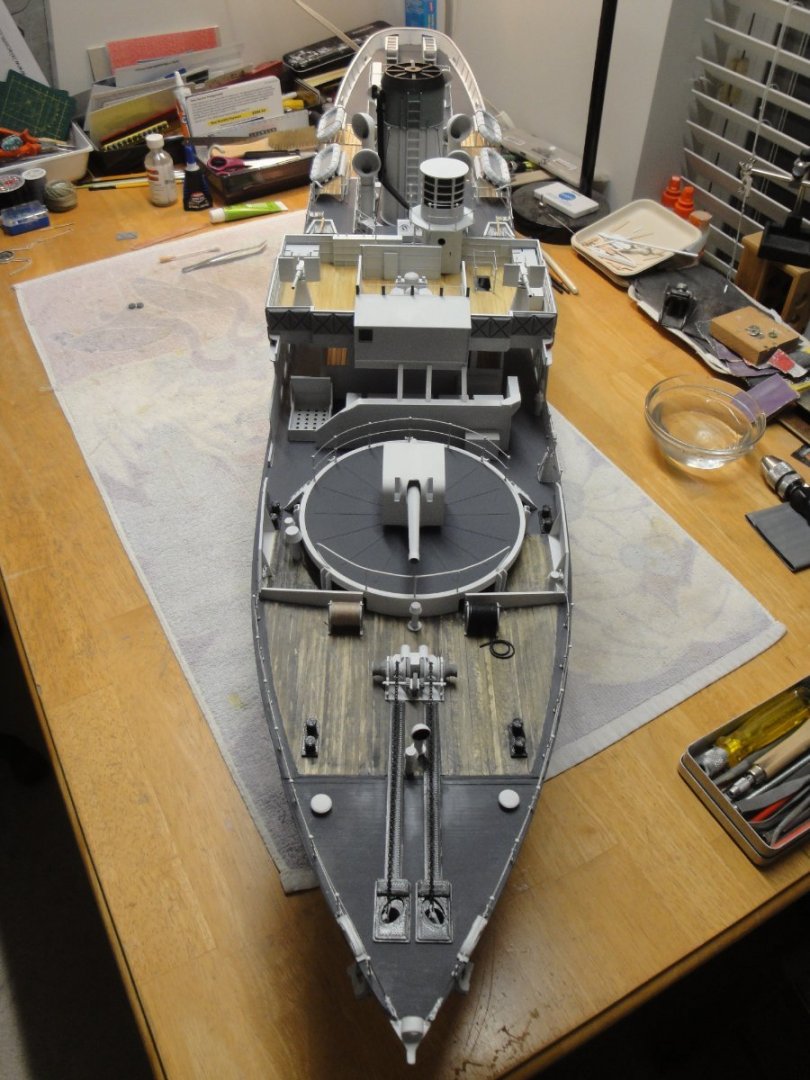
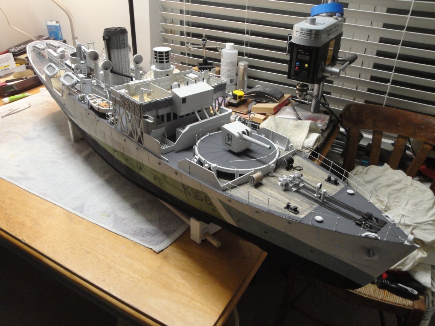
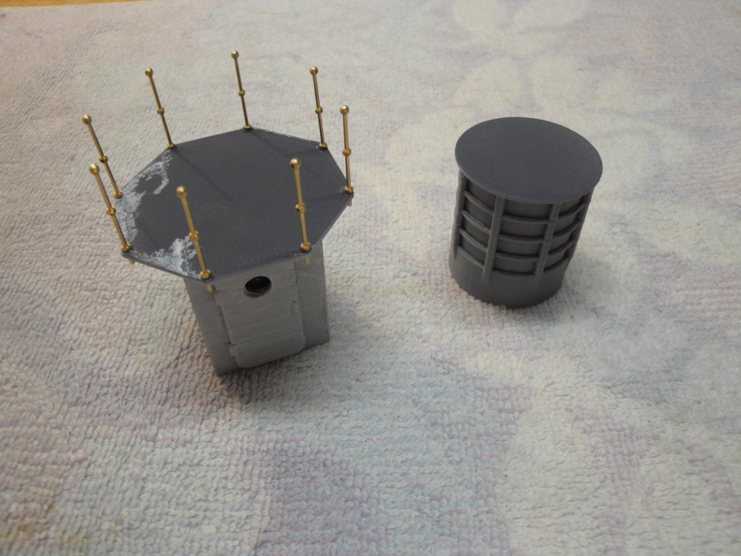
A quick update on the BENSWORX Virtual kit, slightly improved. I have been working on the main bridge and this is the result. The main bridge is printed in one large part: Resulting in this solid bridge: There are pros and cons with this way of doing. The Pros are that the part is very sturdy, easy to remove from the main cabin (for RC application) and relatively easy to finish. The Cons are that it does not offer too many details and makes the planking of the bridge, a tedious challenge. The original bridge was surrounded by canvas stretched on a tubular structure. The 3D print renders some of that aspect, at least from the inside. Anal modelers will likely cut everything and build the sides from soldered brass wires, covered by a thin canvas made of fabric. I thought about that .... for about one minute. Planking takes a lot of precise and small cuts and is labor of patience. I used two varieties of wood and I am not sure if the central part is planked or not. It probably is.... On the rear wall, the small shelves are used to store all the pennants and flags. This is again highly simplified on this 3D kit. A coat of AGE-IT finishes the wood and gives it a nice blond hue: Then, it is the relatively easy task of gluing all the parts, after painting them. The radar enclosure is unfortunately simplified and would have to be entirely rebuilt, if you wanted to replace the solid PLA by transparent films. Overall, the end result is not too bad and blends harmoniously with the rest of the ship. The shielding panels are installed, in the front and sides of the bridge. The rear wall of the bridge was apparently not protected, according to the pictures I saw. The two Oerlikon guns were printed using a resin printer. I need to find some Canadian sailors to populate that bridge..... The radar (above) is carefully painted to simulate the inside of the radar enclosure (dark). That part could be represented with a canvas covering it, if you decide to picture your Corvette in a harbor. The staircase going to the main deck and the ammos storage bins. I have added a small windshield which is not part of the kit. Overall view of the beast: I still have to work on the mast and finish the 6th module, comprising the depth charges deck and stern. I hope you are enjoying that big project. Yves


- 321 replies
-
- 17
-
-
-
- Finished
- Flower-class
- (and 1 more)