yvesvidal
-
Posts
3,634 -
Joined
-
Last visited
Content Type
Profiles
Forums
Gallery
Events
Everything posted by yvesvidal
-
 Truly museum quality and a display of what PE can bring to a model, in the 21st century. Yves
 -
Lots of engineering going into that giant model. It is almost like building a scale 1:1 ship. Yves
-
Beautiful model and very convincing rigging. Well done. Yves
-
Lovely. You must be happy that there are some rat lines.... Yves
- 28 replies
-
- 4
-

-
- vanguard models
- Brixham trawler
- (and 2 more)
-
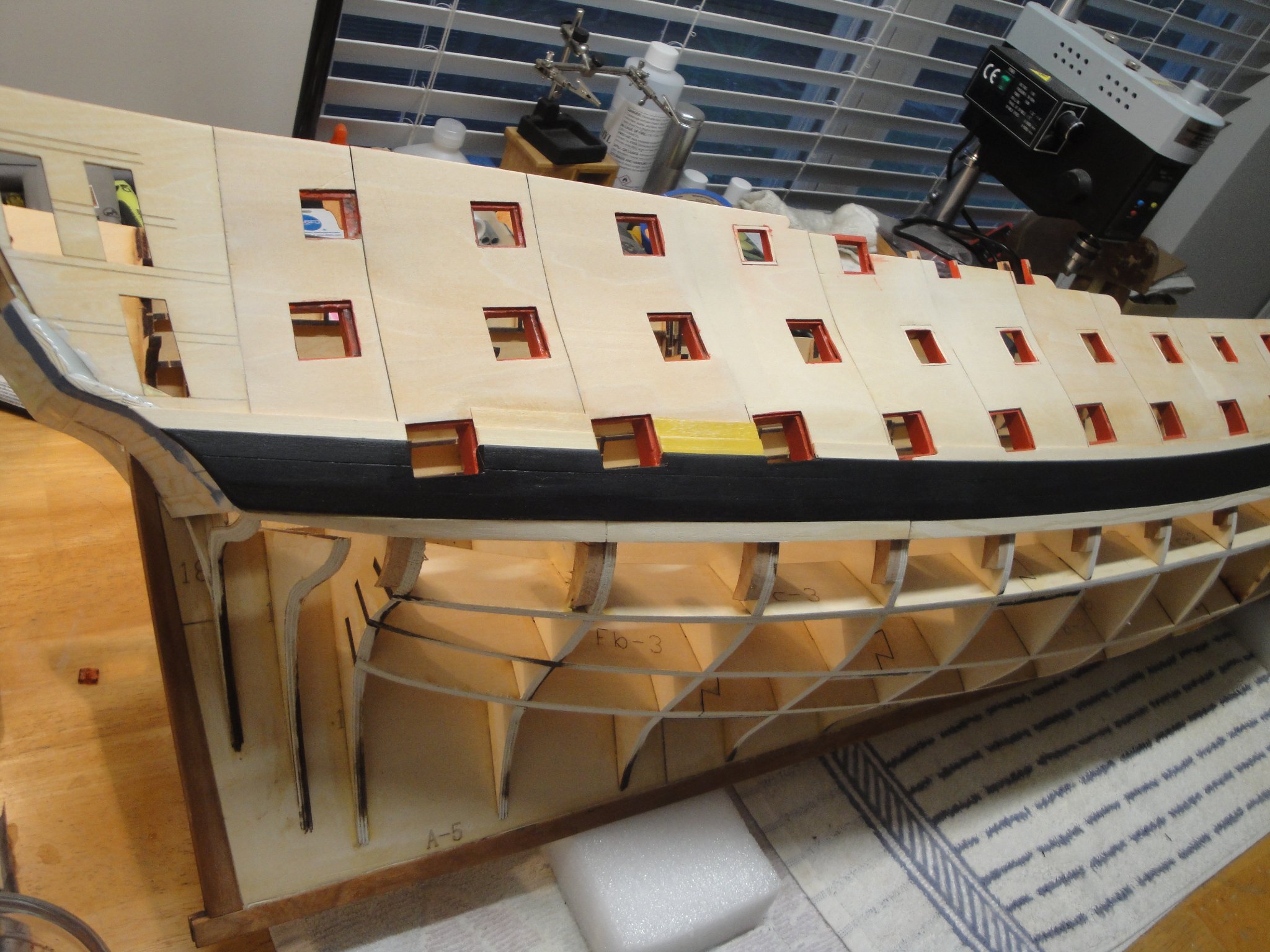
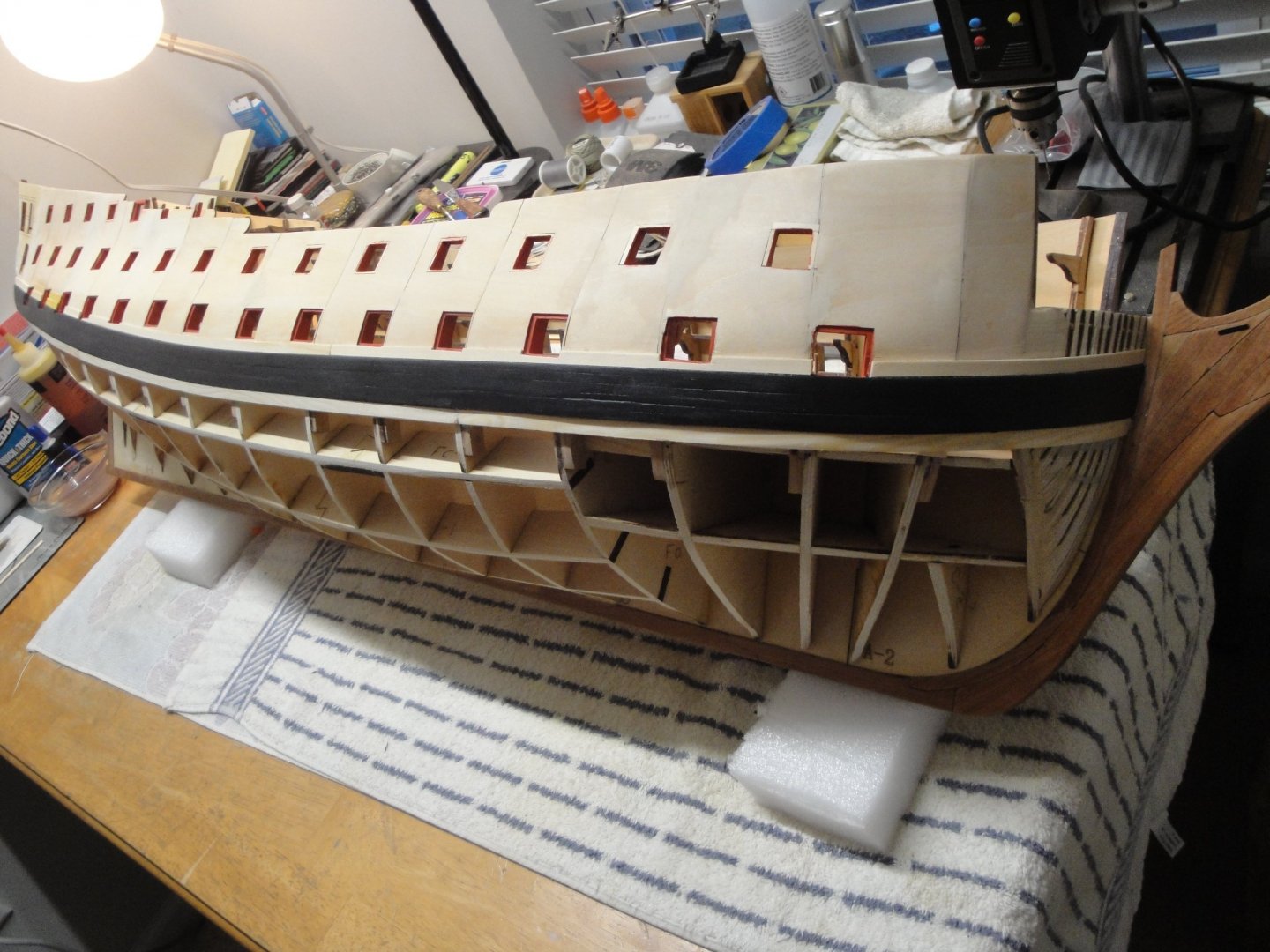
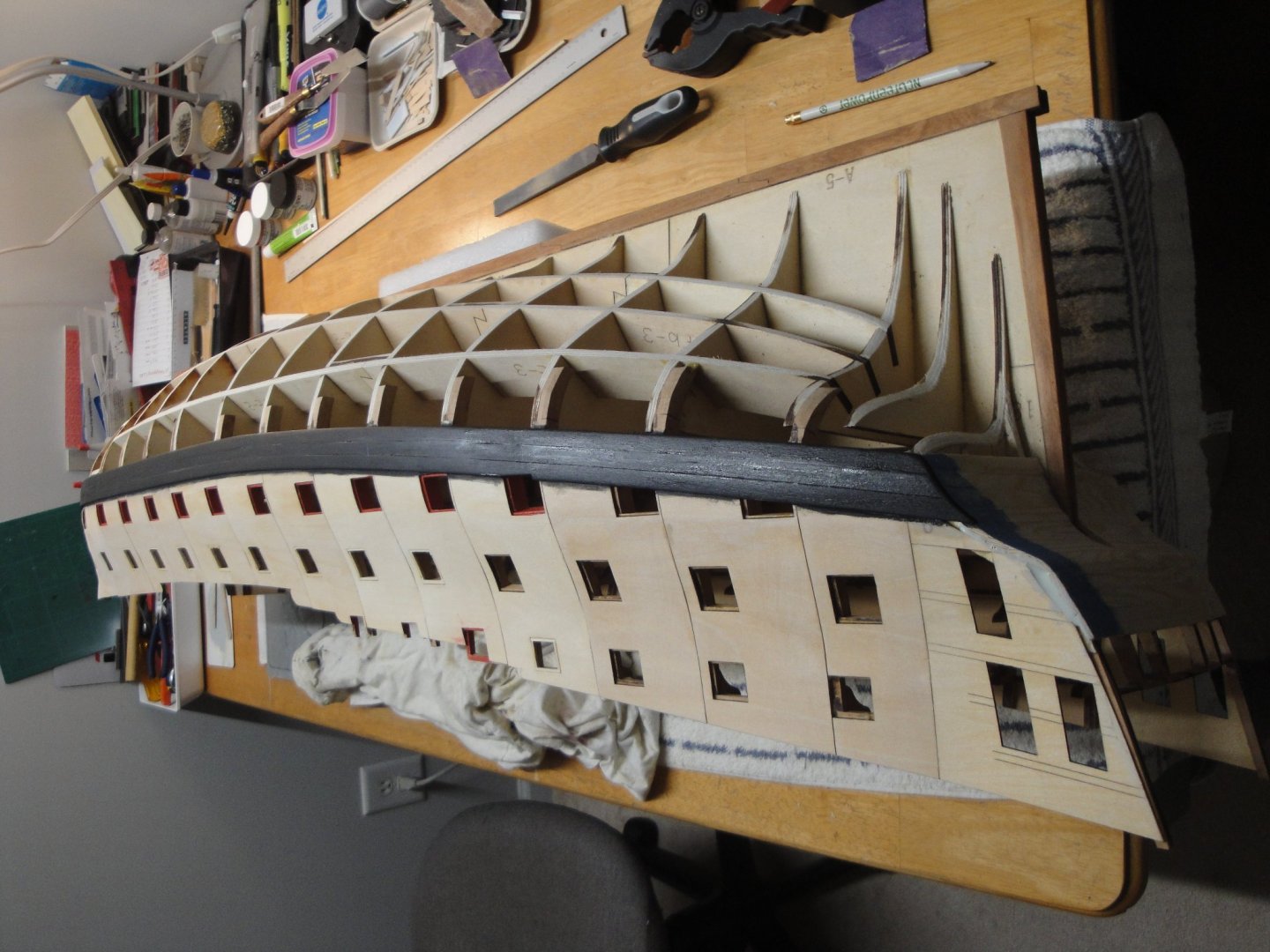
The starboard side is pretty much ready for planking. Main, lower and upper wales have been installed and all gun ports sanded and painted: Now, I just have to do the exact same thing on the port side.... Yves
-
Wonderful results on the mainsail. It is looking really neat. Yves
- 127 replies
-
- 1
-

-
- Bowdoin
- Arctic Exploration
- (and 3 more)
-
D9R by Kevin - Meng - 1/35 - PLASTIC - started 2015
yvesvidal replied to Kevin's topic in Non-ship/categorised builds
Interesting kit Kevin. I like the fact that it is not an armor vehicle. Yves -
Wonderful work and very nice planking. Yves
-
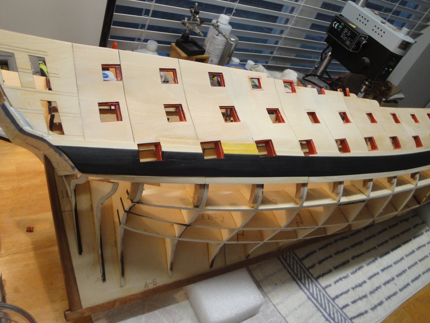
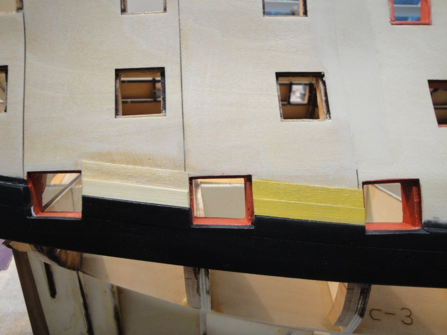
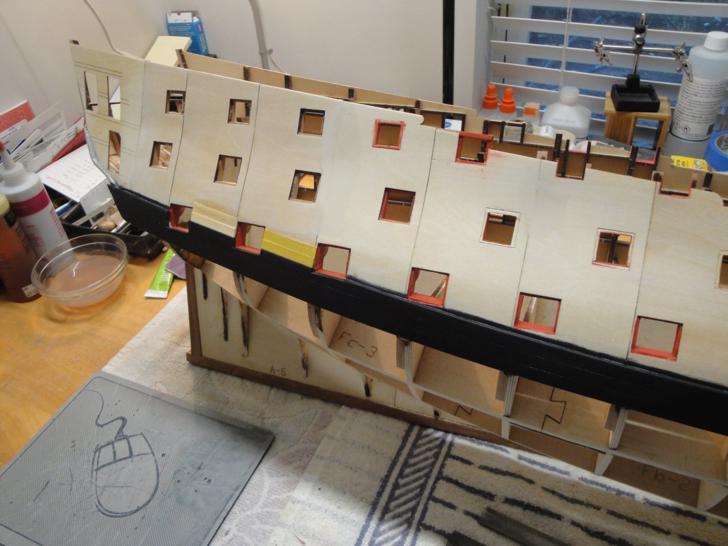
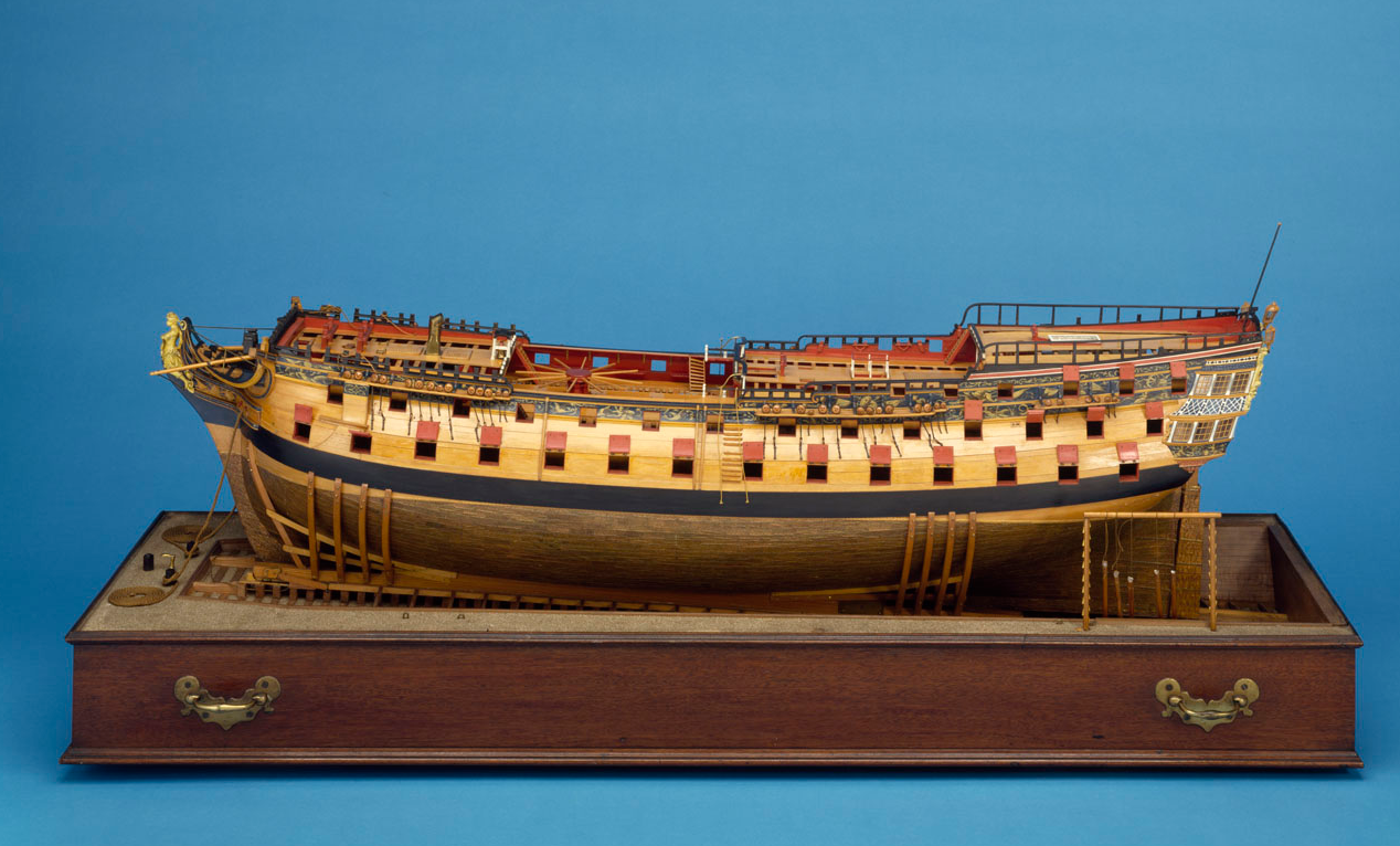
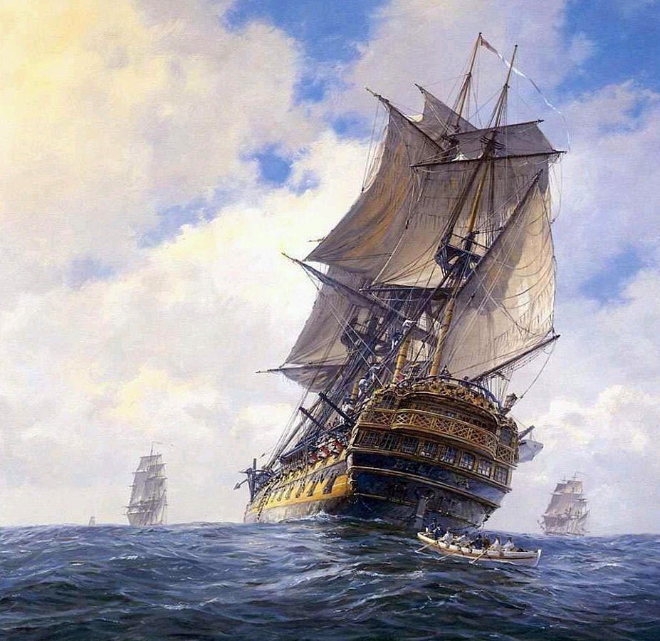
I am exploring some colors for the upper part of the hull and the channels: On the left side, we have Wipe-On-Poly on basswood and maple strips. The WOP may get darker with multiple applications. On the right side, Minwax Mustard water based color. The mustard will get duller with time. Overall view to get a better feel: Let me know your preferences and some other tricks to color the maple and basswood. The original model is shown below: And a painting of HMS Bellona by Geoff Hunt: Yves
- 507 replies
-
- 12
-
-
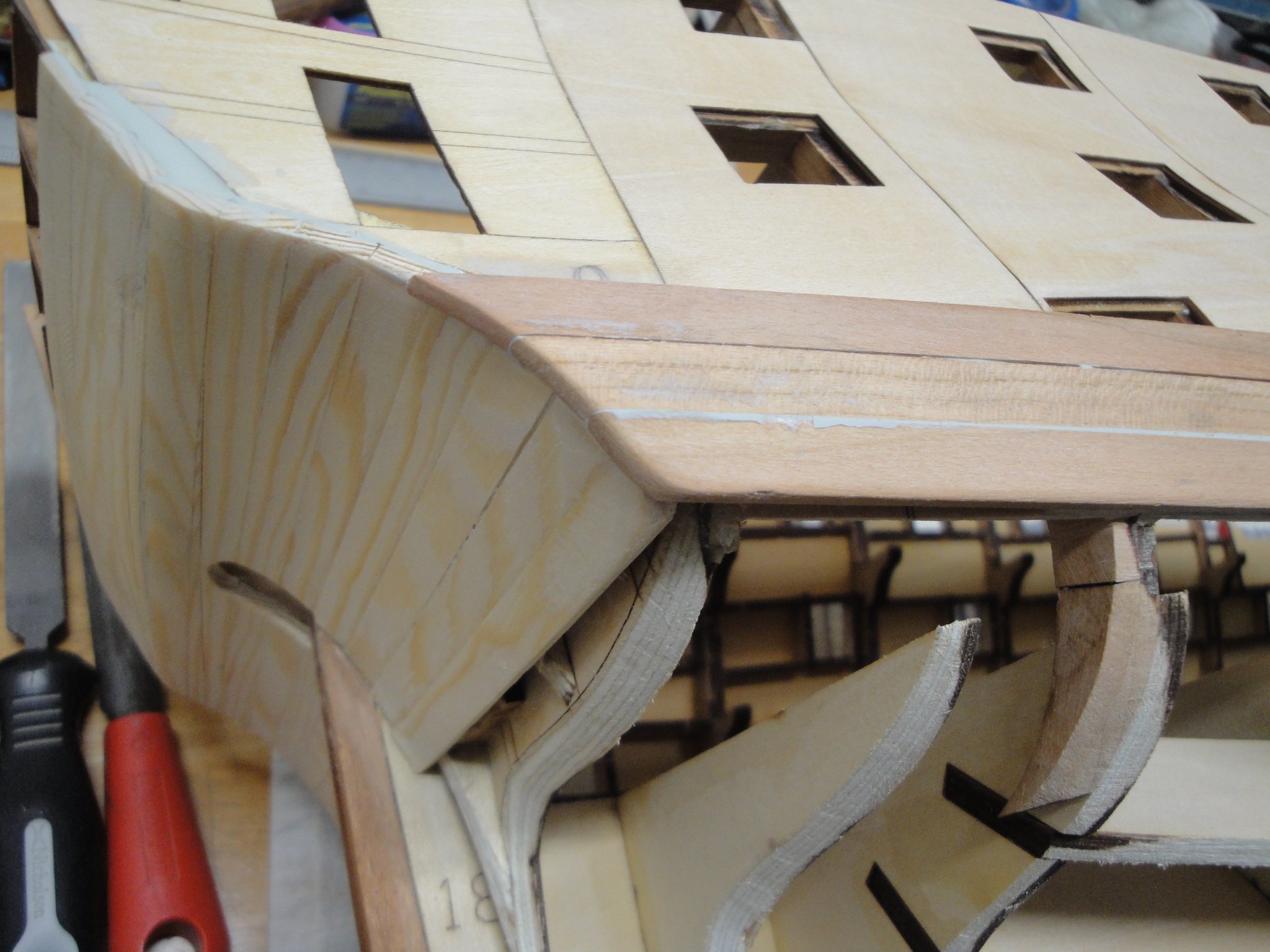
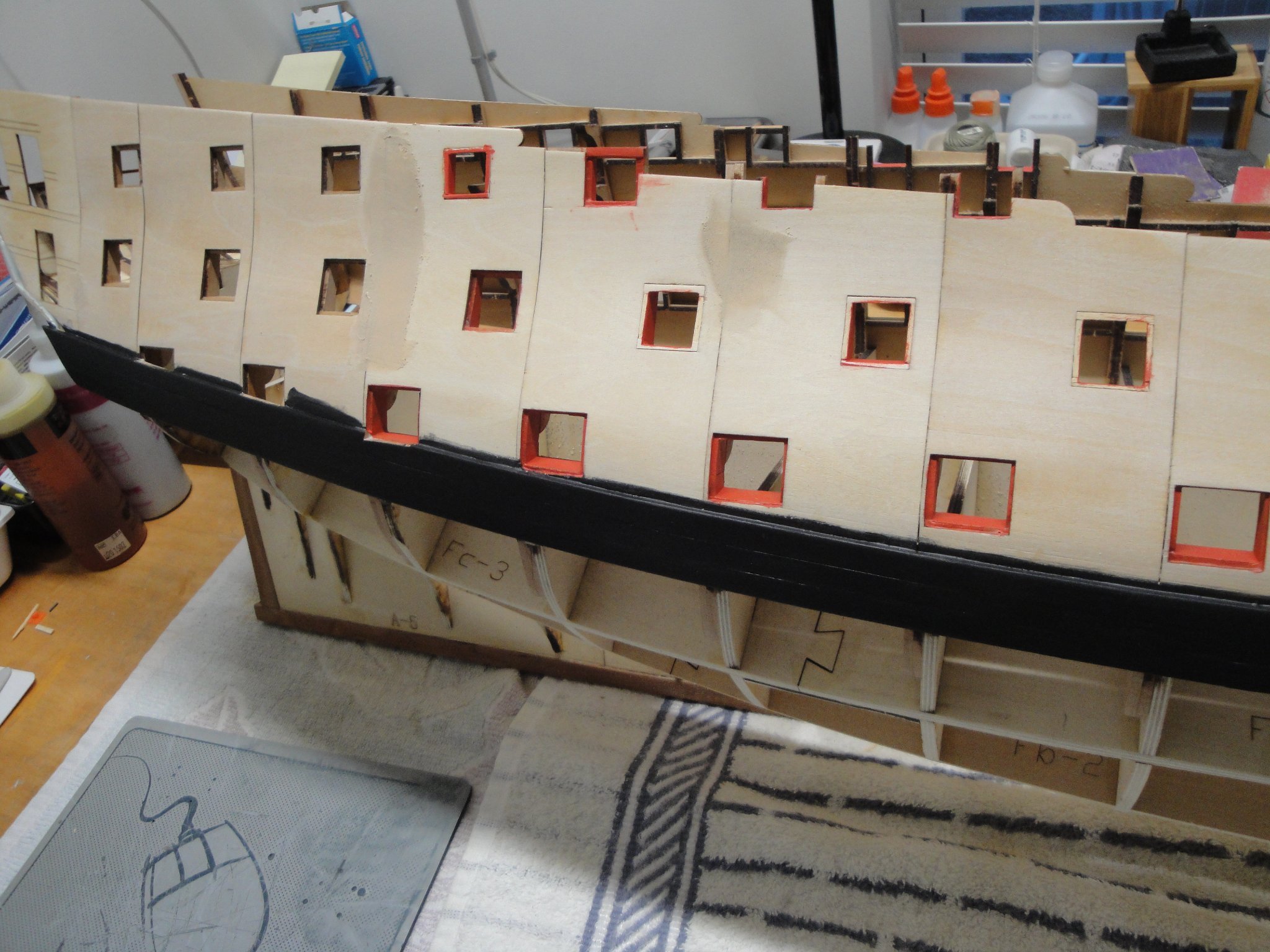
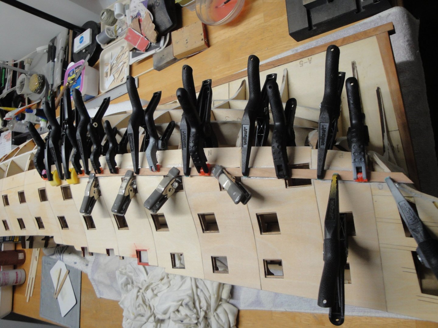
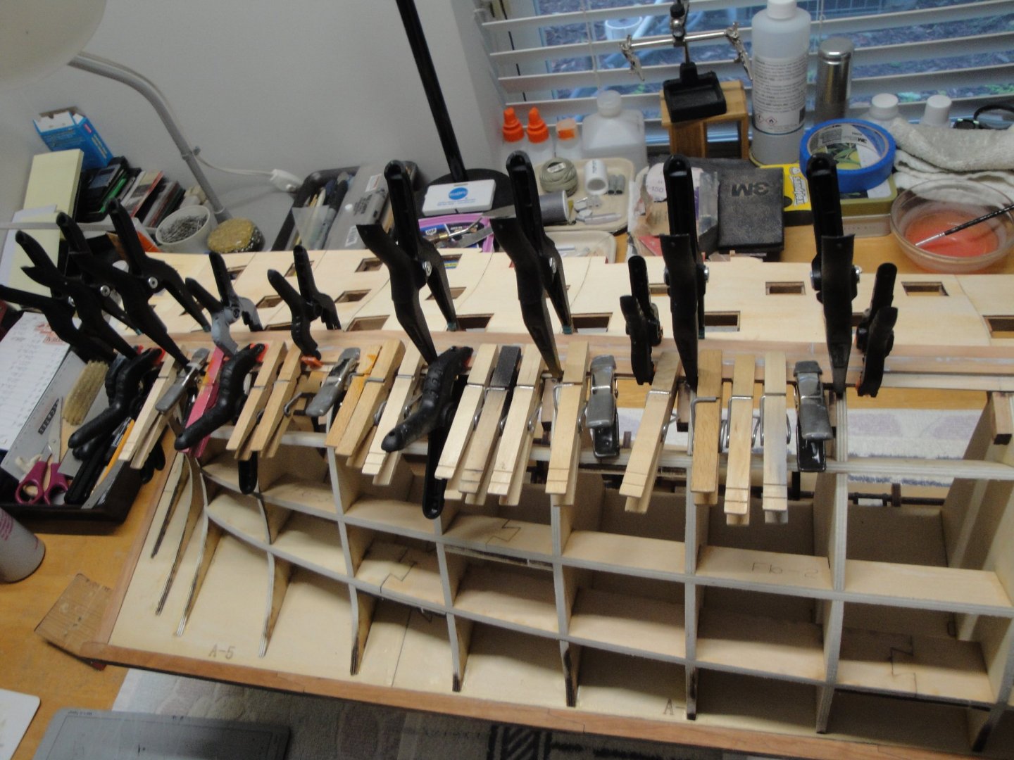
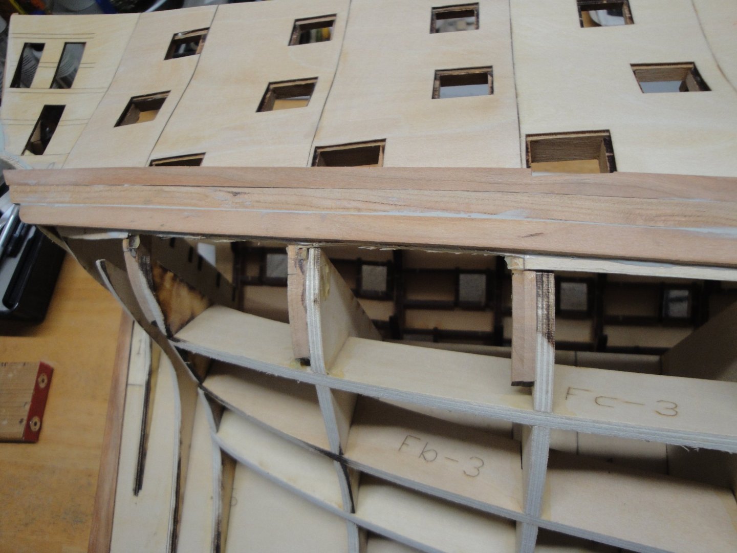
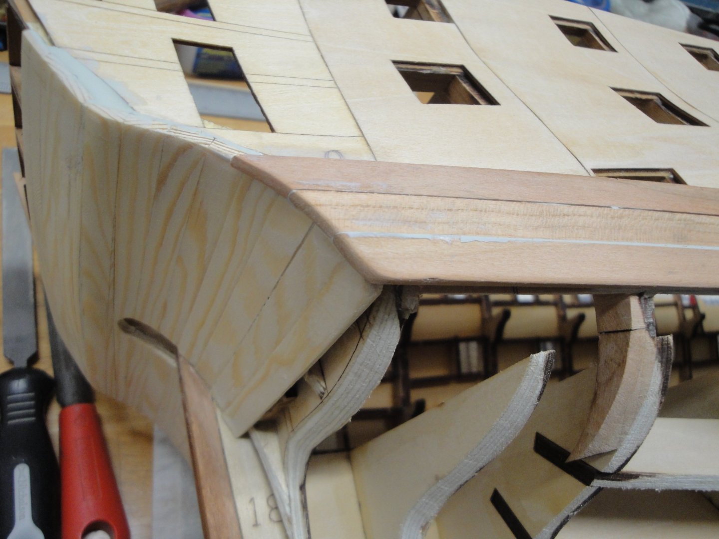
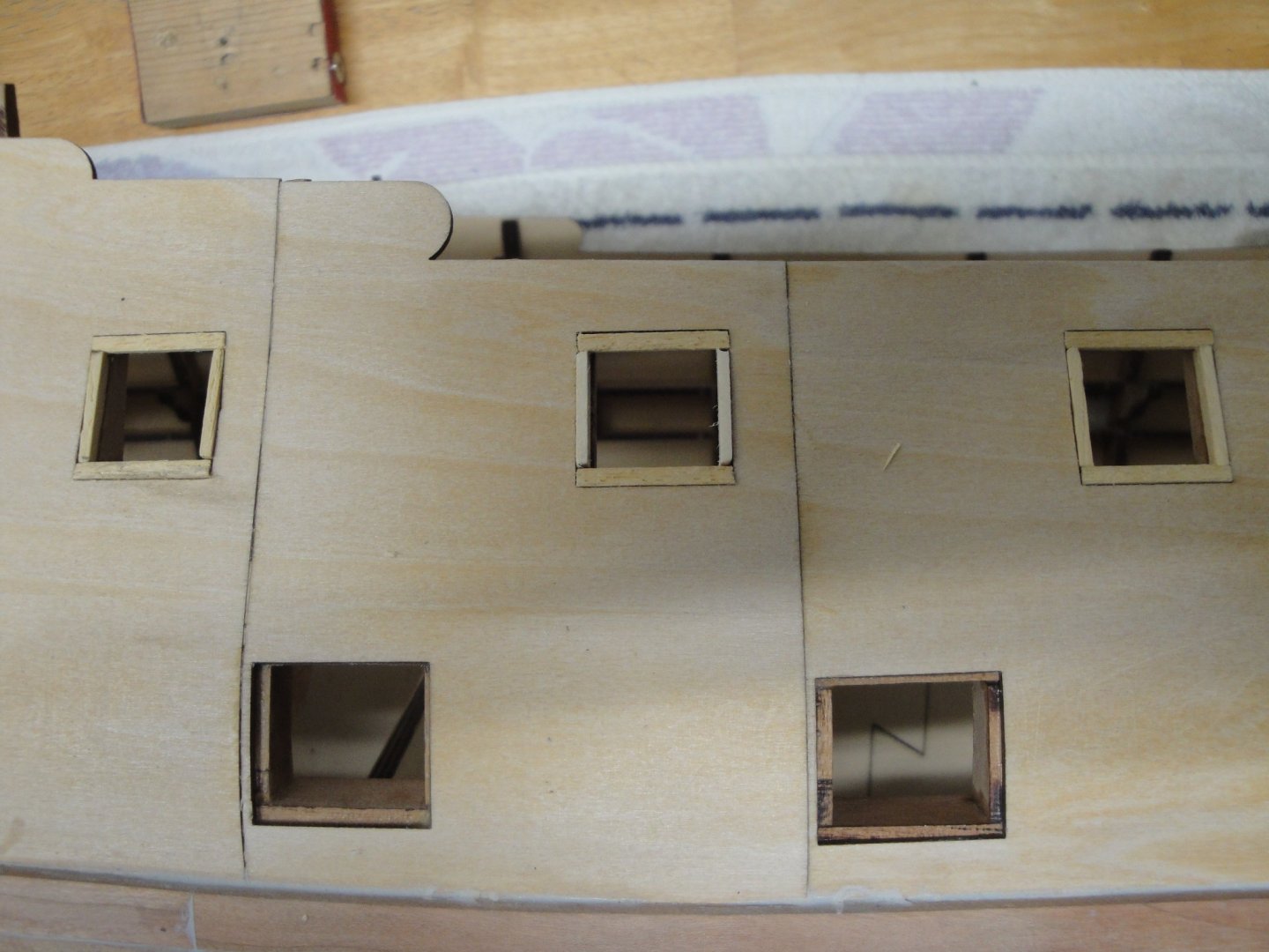
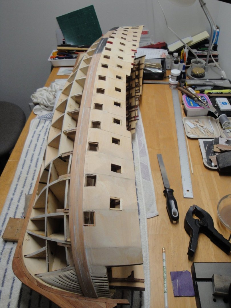
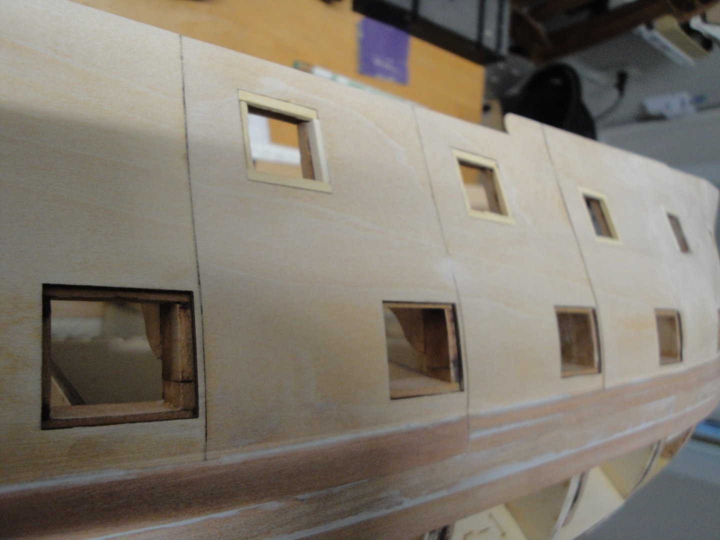
Breaking away from the CAF instructions (which are recommending planking the lower hull first) I went ahead and worked on the Wales. After carefully measuring and getting the right positioning of these from pictures and the blueprint, I went ahead and started gluing the thick and stiff strips of cherry wood, provided in the kit. These are 8.5 mm wide by 3 mm thick and quite a challenge to bend. Some warm water allowed me to follow the natural curve of the hull: The wales are glued with slow curing two components resin epoxy. I have to wait about 6 to 8 hours for each strip and there are nine strips total. Maybe I need to be less generous on the amount of glue.... Wales are glued staggered, in order to define a nice and regular curve, along the hull. Three strips are about 25 mm wide, which is one mm short of what the blueprint is indicating. However, following the Anatomy of the Ship book, I will be approaching the wales on a more gradual basis, instead of the way it is done in the kit. In the kit, we have 3 mm thick (wales) and we then plank the upper hull with 0.4 mm maple strips. That creates a brutal transition which is contradictory to what the reference book is showing. Instead, I will use 3 mm for the wales, 1.5 mm transition strip (not provided in the kit) and the 0.4 mm upper hull planking. Still plenty of sanding to be done.... Another aspect of the upper hull that needs to be addressed, is the upper deck gun ports: These present a large opening which is not right and will create a void, when the external planking is installed. Using 1.5 x 1.5 mm strip (not provided in the kit), I am filling up the gap created between the outer shells and the futtocks. The lower gun deck, does not need that treatment since the gun port lids are supposed to be inserted there. When dry, everything is sanded smoothly and the upper hull planking could be technically started at that point. We will not do that quite yet.... An overall view of the starboard side with the wale installed. To accommodate the sharp curve at the bow, I took my 8.5 x 3 mm cherry strips and split them in two, on the length of the bow curve. After a soaking in alcohol, the smaller strips created by the cut are easier to bend and less likely to break. At the bow, you can actually see 6 small strips. About four coats of Model Shipways acrylic black paint to get a sense of the wale: Still plenty of sanding to be done and another four coats to make it look nice. Another point to not forget, is the painting of the gun ports and some wood putty in places where they may be small imperfections in the smoothness of the hull. I am trying to finish one side before moving to the port side of the hull. I hate repetitive tasks.... when building a 74 guns ship, what can you expect? Yves

- 507 replies
-
- 16
-
-
Impressive and beautiful. You pulled it out very nicely. Yves
-
These wagons were truly luxurious. Yves
-
Kevin The Bellona copper tiles were 4 feet by 15 inches according to the Anatomy of the Ship. At 1/48th scale, that translates to: 2.5 cm x 0.8 cm. The sample tiles that Tom sent me are about half the required size. I suspect they must have 1/64th scale tiles and that does not work too well, on that huge hull. Yves
-
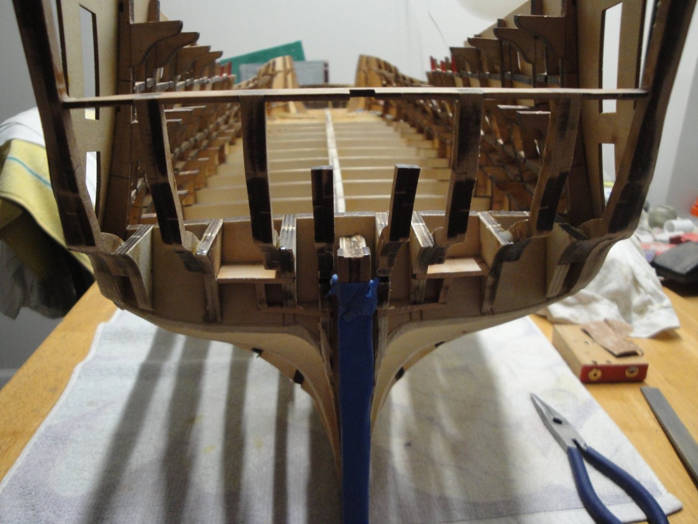
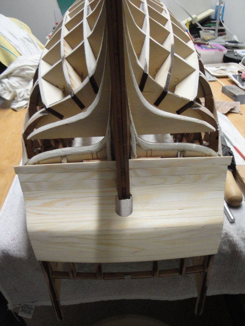
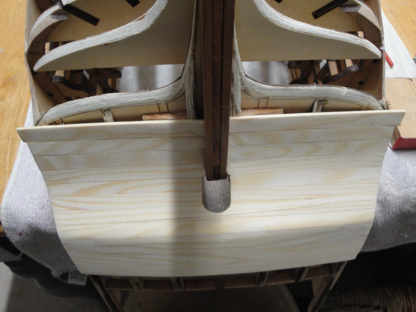
The planking on the poop is not perfect but everything will be painted and I will use some wood putty to fill the imperfections. Now, I need the opinions of experts: CAF recommends starting to plank the bottom of the hull, without any comments, of course. I have been looking at various Build Logs and some people start with the wales. I am thinking about starting with the wales to really define the hull and make it as symmetric as possible and also start planking the bottom of the hull, near the keel. Once the wales are in place and correctly sanded, I was thinking about planking from the wales down to the keel. There is no second planking on that large model and all the planks are 8 mm wide by 3 mm thick lime wood. Tough stuff to handle and very stiff. The hull is supposed to be coppered but I have not made up my mind yet and the CAF tiles are way too small for this model. I would have to procure them from another source. Suggestions, recommendation, hints, advices are the most welcome. Yves
-
This is coming along very nicely. Beautiful construction. Yves
- 17 replies
-
- 1
-
-
- norwegian sailing pram
- Finished
- (and 1 more)
-
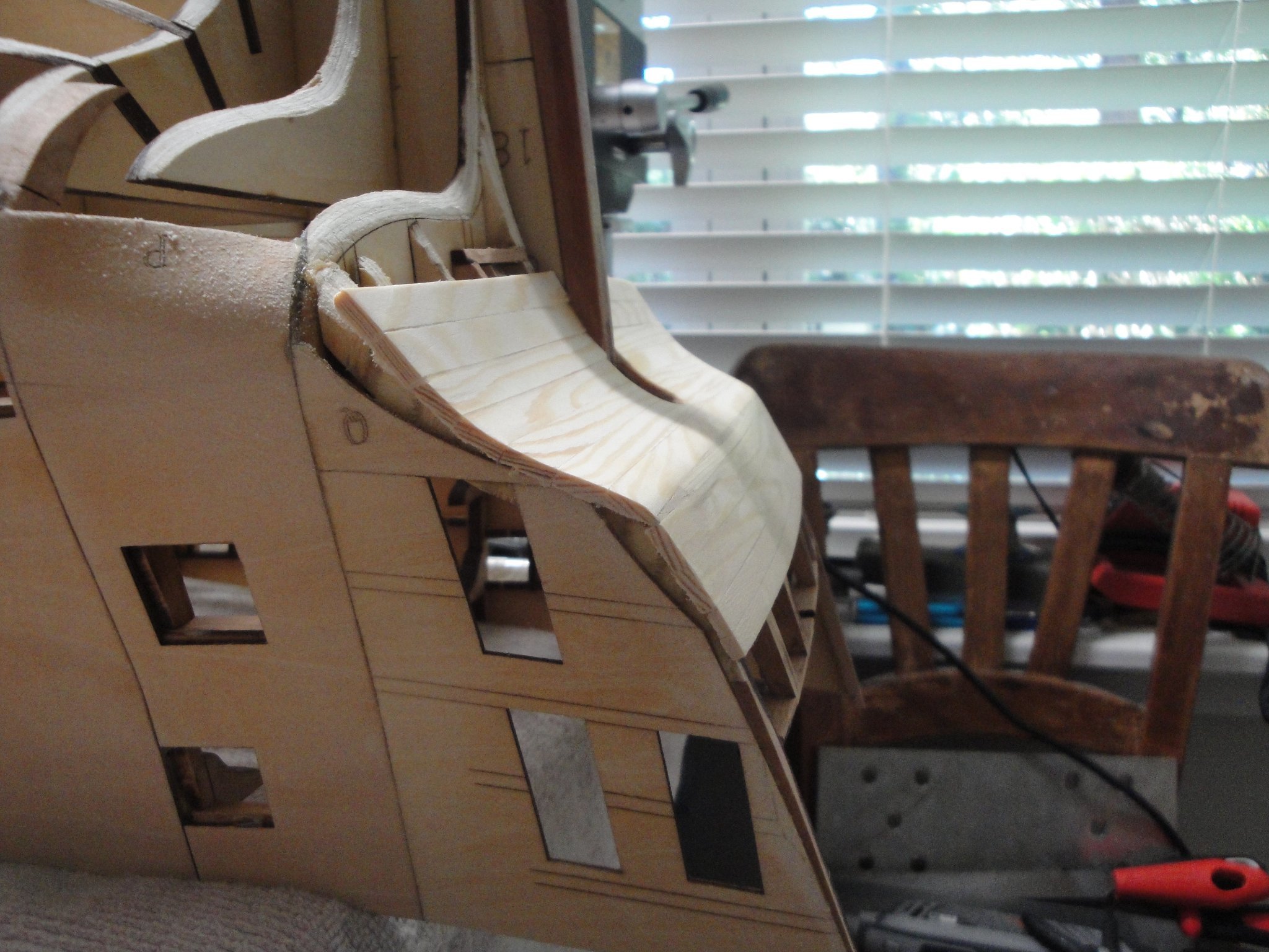
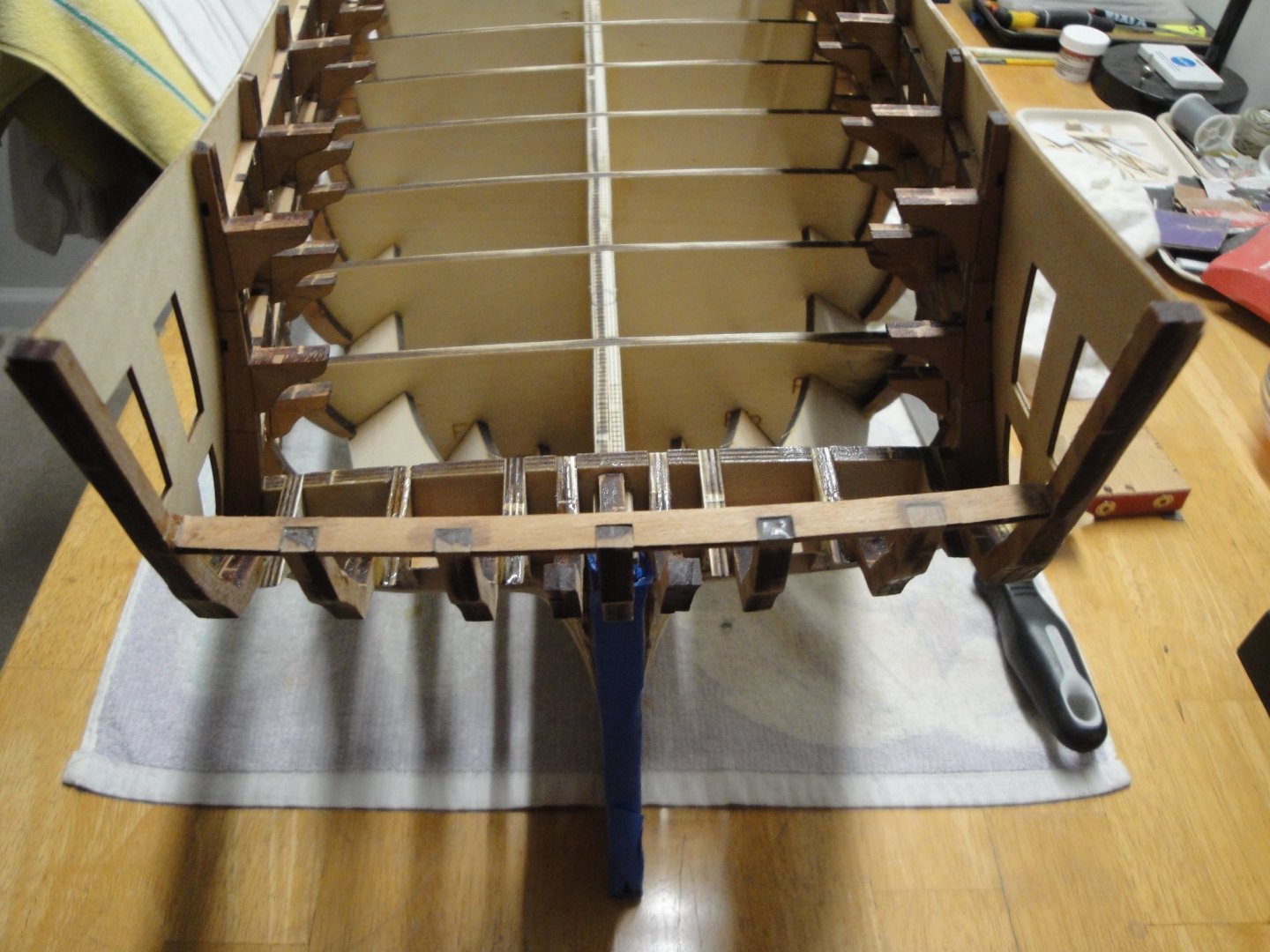
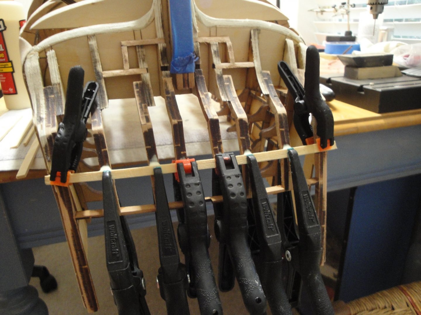
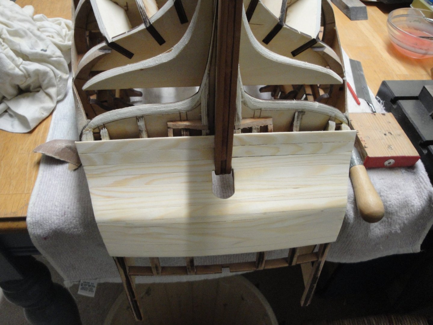
Moving along with the stern. I have glued the famous #25 part with 2 components epoxy glue, after carefully checking alignment and dimensions. I do not have Session #4 yet, which includes the balcony and floor that will be resting on that part, but I suspect it will work fine. The central futtock #1, is not glued since it will be discarded: After positioning carefully the windows, I am gluing the first plank on the stern. This one and the following will be curved after soaking them in luke warm water. Not easy as these planks are made of 3 mm thick lime wood (I suspect it is lime). Moving on with the planking of the poop: Yves

- 507 replies
-
- 16
-
-

-
Very clever way of doing these. Something to remember.... Yves
-
Beautiful bilge pumps and cranks. Man, you are brave to attempt another one of these builds.... This one is actually very nice. Yves
-
What an impressive ship and model. I will be following with a lot of interest as I am building a much simpler model (kit), the Bellona from CAF, also in 1/48th scale. Yves
-
Nice progress Alan. I like that juxtaposition of raw and harsh PLA and soft and smooth wood. It makes for a nice contrast. On a side note, I need to resume my build if I want to have a chance to finish it before you.... Busy with the HMS Bellona right now.... Yves
- 460 replies
-
- 5
-
-
- Finished
- Flower-class
- (and 1 more)
-
That is a massive tiller. Yves
-
My favorite glue as well. I grew up in France and build my first planes with UHU Hart. By far the best glue for light woods. Unfortunately, impossible to find in the USA. Testors Cement for wood is a pale substitute for UHU Hart. Yves
-
Very nice. Yves
-
I like that Tinkerbell and your kit of course.... Yves